 |
Matronics Email Lists
Web Forum Interface to the Matronics Email Lists
|
| View previous topic :: View next topic |
| Author |
Message |
pdn8r(at)yahoo.com
Guest
|
 Posted: Sun Nov 16, 2008 1:05 pm Post subject: Flap Switch Wiring Posted: Sun Nov 16, 2008 1:05 pm Post subject: Flap Switch Wiring |
 |
|
OK, my stupid factor is in high gear today.  I'm having difficulty with the flap switch wiring as shown on 6B-20.  I've attached a copy.  Somebody help me out, as I can't seem to get it right.  I see that the black wire from the flap motor goes to the #1 lug.  Red goes to number 3 lug.  Ground goes to #2.  Hot wire from the buss goes to 5 Beyond that I get confused.  I've attached the diagram.


Bill Pagan
| | - The Matronics Zenith601-List Email Forum - | | | Use the List Feature Navigator to browse the many List utilities available such as the Email Subscriptions page, Archive Search & Download, 7-Day Browse, Chat, FAQ, Photoshare, and much more:
http://www.matronics.com/Navigator?Zenith601-List |
|
| Description: |
|

Download |
| Filename: |
6B-20.pdf |
| Filesize: |
219.6 KB |
| Downloaded: |
655 Time(s) |
|
|
| Back to top |
|
 |
ideaz1(at)sbcglobal.net
Guest
|
| Posted: Sun Nov 16, 2008 2:08 pm Post subject: Flap Switch Wiring |
|
|
Hi Bill, You forgot to ask a question... If you  want, call me at 775-671-0852 and I'll talk you through the wiring  here.


 Essentially the ground section of the switch is  traded with the power section to reverse the direction of the motor, and the  limit switches interupt the power whenever they are used on the power  side.


 I'd like to know why your plans, from 2005 have the  limit switches and my plans from 2008 do not?

 Dirk Z. Carson City


 ---
| | - The Matronics Zenith601-List Email Forum - | | | Use the List Feature Navigator to browse the many List utilities available such as the Email Subscriptions page, Archive Search & Download, 7-Day Browse, Chat, FAQ, Photoshare, and much more:
http://www.matronics.com/Navigator?Zenith601-List |
|
|
|
| Back to top |
|
|
jaybannist(at)cs.com
Guest
|
| Posted: Sun Nov 16, 2008 2:20 pm Post subject: Flap Switch Wiring |
|
|
Dirk,
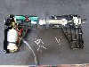
There was a change in the flap actuation system. The older system has the flap motor drive a screw which extends the actuator tube and the actuator arm. The tube has a collar at the screw end that actuates the limit switches. I don't know that much about the newer system, but understand that it is called a "linear actuator" and does away with the limit switches.
Jay in Dallas
Do not archive
--
| | - The Matronics Zenith601-List Email Forum - | | | Use the List Feature Navigator to browse the many List utilities available such as the Email Subscriptions page, Archive Search & Download, 7-Day Browse, Chat, FAQ, Photoshare, and much more:
http://www.matronics.com/Navigator?Zenith601-List |
|
|
|
| Back to top |
|
|
craig(at)craigandjean.com
Guest
|
| Posted: Sun Nov 16, 2008 2:36 pm Post subject: Flap Switch Wiring |
|
|
| Quote: | I'd like to know why your plans, from 2005 have the limit switches and my plans from 2008 do not?
|
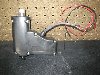
Because Zenith replaced the “open” flap actuator (with exposed micro-switches that you have to wire yourself) with a “sealed” unit where the limits switches are hidden and pre-wired (picture attached). Also unless there is some adjustment inside the casing on the new style actuator there is no adjustment.
Plans page for new style actuator here:
http://www.zenithair.com/zodiac/xl/data/6b19.pdf
Photo guide showing old style actuator here:
http://www.zenithair.com/zodiac/xl/data/6-b-19.pdf
-- Craig
| | - The Matronics Zenith601-List Email Forum - | | | Use the List Feature Navigator to browse the many List utilities available such as the Email Subscriptions page, Archive Search & Download, 7-Day Browse, Chat, FAQ, Photoshare, and much more:
http://www.matronics.com/Navigator?Zenith601-List |
|
| Description: |
|
| Filesize: |
153.22 KB |
| Viewed: |
754 Time(s) |
|
|
|
| Back to top |
|
|
eddies
Joined: 20 Jun 2006
Posts: 40
Location: Australia
|
| Posted: Sun Nov 16, 2008 2:48 pm Post subject: Re: Flap Switch Wiring |
|
|
Hi Bill,


Sorry if this is stating the obvious...


Start with your flap switch (the one you will mount in the panel of your aircraft), it can be oriented in any direction, just choose a set of contacts that will be your up and the other to be your down position and stick with this for all the wiring you do. This will all be done looking at the back of the switch.


Your limit switches should be labeled to indicate which is the common, normally open (NO) and normally closed (NC) connections. If not use a multi meter set to ohms to determine the orientation.


Start your wiring by connecting your Black or negative wires first;


1. Black wire (aircraft ground) to pin 2 of your flap switch (center right hand pin on your flap switch)

2. Black wire from pin 1 of the flap switch (bottom right hand pin) to the normally closed pin of the flap UP limit switch, this will be the switch that is closest to your pilots seat.

3. Run the black wire from the flap motor back to normally closed pin on the same limit switch we just wired in step 2 above.

4. Black wire (aircraft ground) from pin 3 (top right pin of your flap switch) to the common pin of the flap down limit switch (this switch should be the one furthest from your pilots seat).

5. Run the red wire from you flap motor back to the same common pin that was connected in step 4 above.


Now we run the 12V positive wiring


1. Red wire (from aircraft 12V buss) to pin 5 of your flap switch (center left hand pin).

2. Run a Red wire from pin 4 (bottom left hand pin on your flap switch) to the normally closed pin of the flap down limit switch farthest from your pilot seat.

3. Run a Red wire from pin 6 (top left pin) of your flap switch to the common pin of the flap up limit switch, this is the switch closest to your pilots seat.


Thats it you should be done and have a working set of flaps.


Cheers

Eddie
| | - The Matronics Zenith601-List Email Forum - | | | Use the List Feature Navigator to browse the many List utilities available such as the Email Subscriptions page, Archive Search & Download, 7-Day Browse, Chat, FAQ, Photoshare, and much more:
http://www.matronics.com/Navigator?Zenith601-List |
|
|
|
| Back to top |
|
|
craig(at)craigandjean.com
Guest
|
| Posted: Sun Nov 16, 2008 3:07 pm Post subject: Flap Switch Wiring |
|
|
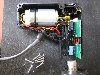
Here is what is inside the new flap actuator. The position of the limit switch nearest the motor is fixed but the one away from the motor is mounted on a circuit board that is glued into a channel. If you reglued it you could decrease the travel by up to about 0.5 inches. From the factory the travel is 2 and 1/8th inches or 54mm.
-- Craig
From: owner-zenith601-list-server(at)matronics.com [mailto:owner-zenith601-list-server(at)matronics.com] On Behalf Of Craig Payne
Sent: Sunday, November 16, 2008 3:36 PM
To: zenith601-list(at)matronics.com
Subject: RE: Flap Switch Wiring
| Quote: | I'd like to know why your plans, from 2005 have the limit switches and my plans from 2008 do not?
|
Because Zenith replaced the “open” flap actuator (with exposed micro-switches that you have to wire yourself) with a “sealed” unit where the limits switches are hidden and pre-wired (picture attached). Also unless there is some adjustment inside the casing on the new style actuator there is no adjustment.
Plans page for new style actuator here:
http://www.zenithair.com/zodiac/xl/data/6b19.pdf
Photo guide showing old style actuator here:
http://www.zenithair.com/zodiac/xl/data/6-b-19.pdf
-- Craig
| | - The Matronics Zenith601-List Email Forum - | | | Use the List Feature Navigator to browse the many List utilities available such as the Email Subscriptions page, Archive Search & Download, 7-Day Browse, Chat, FAQ, Photoshare, and much more:
http://www.matronics.com/Navigator?Zenith601-List |
|
| Description: |
|
| Filesize: |
121.2 KB |
| Viewed: |
743 Time(s) |
|
| Description: |
|
| Filesize: |
155.56 KB |
| Viewed: |
737 Time(s) |
|
|
|
| Back to top |
|
|
ideaz1(at)sbcglobal.net
Guest
|
| Posted: Sun Nov 16, 2008 5:24 pm Post subject: Flap Switch Wiring |
|
|
Thanks for the info about the new  actuator!

 Dirk

 [quote]   ---
| | - The Matronics Zenith601-List Email Forum - | | | Use the List Feature Navigator to browse the many List utilities available such as the Email Subscriptions page, Archive Search & Download, 7-Day Browse, Chat, FAQ, Photoshare, and much more:
http://www.matronics.com/Navigator?Zenith601-List |
|
|
|
| Back to top |
|
|
Thruster87
Joined: 16 Apr 2008
Posts: 193
Location: Australia
|
| Posted: Mon Jun 08, 2009 11:22 pm Post subject: Re: Flap Switch Wiring |
|
|
Does anyone have a wiring diagram for the NEW linear actuator with just the TWO wires and the Toggle switch to operate it. Cheers
| | - The Matronics Zenith601-List Email Forum - | | | Use the List Feature Navigator to browse the many List utilities available such as the Email Subscriptions page, Archive Search & Download, 7-Day Browse, Chat, FAQ, Photoshare, and much more:
http://www.matronics.com/Navigator?Zenith601-List |
|
|
|
| Back to top |
|
|
vk3eka(at)bigpond.net.au
Guest
|
| Posted: Tue Jun 09, 2009 1:48 am Post subject: Flap Switch Wiring |
|
|
Alan ?


PDF of my drawing attached.


Cheers


Peter

Wonthaggi Australia

http://zodiac.cpc-world.com


--
| | - The Matronics Zenith601-List Email Forum - | | | Use the List Feature Navigator to browse the many List utilities available such as the Email Subscriptions page, Archive Search & Download, 7-Day Browse, Chat, FAQ, Photoshare, and much more:
http://www.matronics.com/Navigator?Zenith601-List |
|
| Description: |
|
Download |
| Filename: |
XL_Electricals.pdf |
| Filesize: |
14.65 KB |
| Downloaded: |
533 Time(s) |
|
|
| Back to top |
|
|
Thruster87
Joined: 16 Apr 2008
Posts: 193
Location: Australia
|
| Posted: Tue Jun 09, 2009 1:49 pm Post subject: Re: Flap Switch Wiring |
|
|
Much appreciated.Saved at least 1000 brain cells. Cheers Alan
| | - The Matronics Zenith601-List Email Forum - | | | Use the List Feature Navigator to browse the many List utilities available such as the Email Subscriptions page, Archive Search & Download, 7-Day Browse, Chat, FAQ, Photoshare, and much more:
http://www.matronics.com/Navigator?Zenith601-List |
|
|
|
| Back to top |
|
|
Thruster87
Joined: 16 Apr 2008
Posts: 193
Location: Australia
|
| Posted: Tue Jun 09, 2009 10:27 pm Post subject: Re: Flap Switch Wiring |
|
|
I have attached an updated drawing with the wiring diagram for the flap

motor.Received from Zenith [Caleb Gebhardt] today
| | - The Matronics Zenith601-List Email Forum - | | | Use the List Feature Navigator to browse the many List utilities available such as the Email Subscriptions page, Archive Search & Download, 7-Day Browse, Chat, FAQ, Photoshare, and much more:
http://www.matronics.com/Navigator?Zenith601-List |
|
| Description: |
|
Download |
| Filename: |
6-B-20.pdf |
| Filesize: |
87.43 KB |
| Downloaded: |
527 Time(s) |
|
|
| Back to top |
|
|
|
|
You cannot post new topics in this forum
You cannot reply to topics in this forum
You cannot edit your posts in this forum
You cannot delete your posts in this forum
You cannot vote in polls in this forum
You cannot attach files in this forum
You can download files in this forum
|
Powered by phpBB © 2001, 2005 phpBB Group
|

