 |
Matronics Email Lists
Web Forum Interface to the Matronics Email Lists
|
| View previous topic :: View next topic |
| Author |
Message |
nuckolls.bob(at)aeroelect
Guest
|
 Posted: Thu Oct 22, 2009 3:26 pm Post subject: p-lead signal conditioning or tach gen usage Posted: Thu Oct 22, 2009 3:26 pm Post subject: p-lead signal conditioning or tach gen usage |
 |
|
At 03:56 PM 10/22/2009, you wrote:
| Quote: |
<capav8r(at)gmail.com>
Bob:
I think I know where you are going with the tach gen. We could tap
the side of the case and put a hall effect on it to "watch" the
rotor magnets go by. I suspect the stator windings would need to be
removed. Am I on track?
|
Close. The first time I prototyped a hall-effect
tach transducer, I salvaged the whole front end bell
and shaft. Just enough hardware to grab the engine.
Some time on the lathe produced a new, short rear
end bell and ECB mount. Another lathe-cut part had
12 little rod-magnets pressed into it and positioned
to fly past the hall device on the ECB.
| Quote: | To answer your question, yes, I can get another tach gen for the
engine with no problems. About $150 for a new one...a little less
for a used one. The Hall Effect can be obtained fro Aircraft Spruce.
|
The hall device I'm considering is a little surface
mounted device.
Bob . . .
---------------------------------------
( . . . a long habit of not thinking )
( a thing wrong, gives it a superficial )
( appearance of being right . . . )
( )
( -Thomas Paine 1776- )
---------------------------------------
| | - The Matronics AeroElectric-List Email Forum - | | | Use the List Feature Navigator to browse the many List utilities available such as the Email Subscriptions page, Archive Search & Download, 7-Day Browse, Chat, FAQ, Photoshare, and much more:
http://www.matronics.com/Navigator?AeroElectric-List |
|
|
|
| Back to top |
|
 |
nuckolls.bob(at)aeroelect
Guest
|
 Posted: Thu Oct 22, 2009 6:01 pm Post subject: p-lead signal conditioning or tach gen usage Posted: Thu Oct 22, 2009 6:01 pm Post subject: p-lead signal conditioning or tach gen usage |
 |
|
| Quote: |
Bob, I was thinking of only rectifying one phase not all three. My
thought was that the tach gen is rotating at half engine speed, I'd
get another "peak" in the signal from one phase and essentially
double the frequency.
|
Hmmmm . . . yeah, that would work.
Bob . . .
---------------------------------------
( . . . a long habit of not thinking )
( a thing wrong, gives it a superficial )
( appearance of being right . . . )
( )
( -Thomas Paine 1776- )
---------------------------------------
| | - The Matronics AeroElectric-List Email Forum - | | | Use the List Feature Navigator to browse the many List utilities available such as the Email Subscriptions page, Archive Search & Download, 7-Day Browse, Chat, FAQ, Photoshare, and much more:
http://www.matronics.com/Navigator?AeroElectric-List |
|
|
|
| Back to top |
|
 |
nuckolls.bob(at)aeroelect
Guest
|
 Posted: Mon Nov 02, 2009 6:56 am Post subject: p-lead signal conditioning or tach gen usage Posted: Mon Nov 02, 2009 6:56 am Post subject: p-lead signal conditioning or tach gen usage |
 |
|
At 04:59 PM 11/1/2009, you wrote:
| Quote: | --> AeroElectric-List message posted by: "Craig Winkelmann" <capav8r(at)gmail.com>
Bob:
Put a scope on the tach gen output. The situation is the signal from the tach gen goes to a 5.1 V zener diode, then to a comparator against a reference voltage to generate a square wave.
Attached is the picture of the waveform at low rpm (approx 800). Note the spikes in the wave. Also, the voltage is near the zener voltage so the zener never gets driven into breakdown so that is why the unit has a flakey rpm reading at low
rpm. |
Agreed.
| Quote: | | So, would the waveform squaring circuit you posted in an earlier post work to square this waveform? If so, I have 28 VDC available in the aircraft. I'd need to use a 28-5 V converter chip to get the 5 VDC on the collector as you drew it. Any suggestions for this? |
I don't recall exactly what I sent you earlier
but this is probably similar.
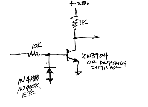
[img]cid:.0[/img]
This squaring circuit has a +0.6v threshold. Since
your 80mS, 5v trashy square wave goes above and below
ground, this will square it up nicely. The diode
keeps the negative excursions at high RPM from going
exceeding the zener breakdown threshold for the NPN
device.
Bob . . .
---------------------------------------
( . . . a long habit of not thinking )
( a thing wrong, gives it a superficial )
( appearance of being right . . . )
( )
( -Thomas Paine 1776- )
---------------------------------------
| | - The Matronics AeroElectric-List Email Forum - | | | Use the List Feature Navigator to browse the many List utilities available such as the Email Subscriptions page, Archive Search & Download, 7-Day Browse, Chat, FAQ, Photoshare, and much more:
http://www.matronics.com/Navigator?AeroElectric-List |
|
| Description: |
|
| Filesize: |
36.63 KB |
| Viewed: |
8631 Time(s) |
|
|
|
| Back to top |
|
 |
ChangDriver
Joined: 15 Sep 2007
Posts: 266
|
 Posted: Mon Nov 02, 2009 2:18 pm Post subject: Re: p-lead signal conditioning or tach gen usage Posted: Mon Nov 02, 2009 2:18 pm Post subject: Re: p-lead signal conditioning or tach gen usage |
 |
|
Bob:


I can eliminate the comparator circuit if I get the output of the squaring circuit to 5 VDC (TTL level).  My thought is to use a Texas Instrument UA7805 Positive Voltage Regulator and connect it to an available 12VDC source in the aircraft.  This should give me a stable 5.0 voltage source.  At 5.0 VDC, the prior squaring circuit diagram used a 4.7K resistor on the collector to limit the current when the transistor is off.  This should square off the signal and provide a TTL level input to the EFIS system in the aircraft.


I can build this on a breadboard and test it in the lab and use a variable speed power drill to rotate the tach gen.


If the above sounds reasonable, I'm off to order the parts from DigiKey.  Thanks for all the help and advice.


Craig


Craig
| | - The Matronics AeroElectric-List Email Forum - | | | Use the List Feature Navigator to browse the many List utilities available such as the Email Subscriptions page, Archive Search & Download, 7-Day Browse, Chat, FAQ, Photoshare, and much more:
http://www.matronics.com/Navigator?AeroElectric-List |
|
|
|
| Back to top |
|
 |
nuckolls.bob(at)aeroelect
Guest
|
 Posted: Tue Nov 03, 2009 8:19 am Post subject: p-lead signal conditioning or tach gen usage Posted: Tue Nov 03, 2009 8:19 am Post subject: p-lead signal conditioning or tach gen usage |
 |
|
At 04:18 PM 11/2/2009, you wrote:
| Quote: | --> AeroElectric-List message posted by: "Craig Winkelmann" <capav8r(at)gmail.com>
Bob:
I can eliminate the comparator circuit if I get the output of the squaring circuit to 5 VDC (TTL level). My thought is to use a Texas Instrument UA7805 Positive Voltage Regulator and connect it to an available 12VDC source in the aircraft. This should give me a stable 5.0 voltage source. At 5.0 VDC, the prior squaring circuit diagram used a 4.7K resistor on the collector to limit the current when the transistor is off. This should square off the signal and provide a TTL level input to the EFIS system in the aircraft.
I can build this on a breadboard and test it in the lab and use a variable speed power drill to rotate the tach gen.
If the above sounds reasonable, I'm off to order the parts from DigiKey. Thanks for all the help and advice. |
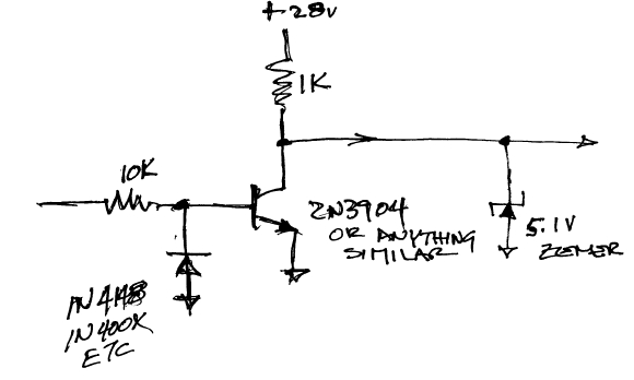
Okay, how about this?
[img]cid:7.1.0.9.0.20091103101407.010d0108(at)aeroelectric.com.0[/img]
How "square" does the signal need to be? If you're driving the
"off the shelf" input to some tachometer originally designed to
attach to a p-lead or some other transducer, the tach should
take care of its own "squaring" internally. It may be that all
you need is to "clean" up the waveform to eliminate bumps and
warts on transitions that can be interpreted as "extra
edges".
Bob . . .
---------------------------------------
( . . . a long habit of not thinking )
( a thing wrong, gives it a superficial )
( appearance of being right . . . )
( )
( -Thomas Paine 1776- )
---------------------------------------
| | - The Matronics AeroElectric-List Email Forum - | | | Use the List Feature Navigator to browse the many List utilities available such as the Email Subscriptions page, Archive Search & Download, 7-Day Browse, Chat, FAQ, Photoshare, and much more:
http://www.matronics.com/Navigator?AeroElectric-List |
|
| Description: |
|
| Filesize: |
45.9 KB |
| Viewed: |
8613 Time(s) |
|
|
|
| Back to top |
|
 |
ChangDriver
Joined: 15 Sep 2007
Posts: 266
|
 Posted: Tue Nov 03, 2009 6:14 pm Post subject: Re: p-lead signal conditioning or tach gen usage Posted: Tue Nov 03, 2009 6:14 pm Post subject: Re: p-lead signal conditioning or tach gen usage |
 |
|
Bob:


In that case, I'll just run the output into the comparator circuit as the signal input to the comparator goes to this:


        signal in  O-------

                                |

                                >

                                <1K>

                                |

                                O---------O------> to comparator

                                |             |

                                >           ---

                       50K   <5>            |

                                |             |

                                gnd         gnd
| | - The Matronics AeroElectric-List Email Forum - | | | Use the List Feature Navigator to browse the many List utilities available such as the Email Subscriptions page, Archive Search & Download, 7-Day Browse, Chat, FAQ, Photoshare, and much more:
http://www.matronics.com/Navigator?AeroElectric-List |
|
|
|
| Back to top |
|
 |
ChangDriver
Joined: 15 Sep 2007
Posts: 266
|
 Posted: Tue Nov 03, 2009 6:19 pm Post subject: Re: p-lead signal conditioning or tach gen usage Posted: Tue Nov 03, 2009 6:19 pm Post subject: Re: p-lead signal conditioning or tach gen usage |
 |
|
Bob:


Well that got messed up when it posted!  Basically, signal in goes to a voltage divider of 1K resistor and 50K resistor with a 5.1V Zener in parallel with the 50K resistor.  The output goes to the comparator.  Output of the comparator goes to the EFIS as a TTL level signal.


Craig
| | - The Matronics AeroElectric-List Email Forum - | | | Use the List Feature Navigator to browse the many List utilities available such as the Email Subscriptions page, Archive Search & Download, 7-Day Browse, Chat, FAQ, Photoshare, and much more:
http://www.matronics.com/Navigator?AeroElectric-List |
|
|
|
| Back to top |
|
 |
nuckolls.bob(at)aeroelect
Guest
|
 Posted: Wed Nov 04, 2009 6:50 am Post subject: p-lead signal conditioning or tach gen usage Posted: Wed Nov 04, 2009 6:50 am Post subject: p-lead signal conditioning or tach gen usage |
 |
|
Yeah, but . . .


  If you study the dynamics of the circuit with the transistor,

  it's "active" window is only a few hundred millivolts wide defined

  by the signal level where the transistor first starts to conduct

  until it is saturated. Only "glitches" that exist within that widow

  are transferred through . . . with gain.


  A straight divider/zener network has an active window of

  about 5 volts but no gain. None the less, the "filtering"

  feature we're looking for is degraded. I'm not saying that

  it won't work . . . give it a try. But you may find that

  the little extra gain and tightening of the window to

  be useful and easy to do.  By the way, since your signal

  of interest goes below ground, the bottom resistor in the

  schematic you propose is probably not necessary.

        Bob . . .


         ---------------------------------------

        ( It's MATRONICS FUND RAISER MONTH!    )

        ( Do your part to keep this marvelous  )

        ( tool sharp and available to all our  )

        ( brothers in the OBAM aviation        )

        ( community.                           )

         ---------------------------------------
| | - The Matronics AeroElectric-List Email Forum - | | | Use the List Feature Navigator to browse the many List utilities available such as the Email Subscriptions page, Archive Search & Download, 7-Day Browse, Chat, FAQ, Photoshare, and much more:
http://www.matronics.com/Navigator?AeroElectric-List |
|
|
|
| Back to top |
|
 |
nuckolls.bob(at)aeroelect
Guest
|
 Posted: Wed Nov 04, 2009 6:51 am Post subject: p-lead signal conditioning or tach gen usage Posted: Wed Nov 04, 2009 6:51 am Post subject: p-lead signal conditioning or tach gen usage |
 |
|
At 08:19 PM 11/3/2009, you wrote:
| Quote: |
<capav8r(at)gmail.com>
Bob:
Well that got messed up when it posted! Basically, signal in goes
to a voltage divider of 1K resistor and 50K resistor with a 5.1V
Zener in parallel with the 50K resistor. The output goes to the
comparator. Output of the comparator goes to the EFIS as a TTL level signal.
|
OH . . . you mean there are other electro-whizzies
posed between our pre-conditioning circuit and the
input to your EFIS?
I thought we were talking about the whole thing.
Perhaps you need to sketch the whole system for
me, I've been seeing it through a gray matter "knothole".
Bob . . .
---------------------------------------
( It's MATRONICS FUND RAISER MONTH! )
( Do your part to keep this marvelous )
( tool sharp and available to all our )
( brothers in the OBAM aviation )
( community. )
---------------------------------------
| | - The Matronics AeroElectric-List Email Forum - | | | Use the List Feature Navigator to browse the many List utilities available such as the Email Subscriptions page, Archive Search & Download, 7-Day Browse, Chat, FAQ, Photoshare, and much more:
http://www.matronics.com/Navigator?AeroElectric-List |
|
|
|
| Back to top |
|
 |
ChangDriver
Joined: 15 Sep 2007
Posts: 266
|
 Posted: Thu Nov 05, 2009 1:38 pm Post subject: Re: p-lead signal conditioning or tach gen usage Posted: Thu Nov 05, 2009 1:38 pm Post subject: Re: p-lead signal conditioning or tach gen usage |
 |
|
Bob:


Here is the circuit that is the current interface between the tach gen and the EFIS tach input.  It was originally designed to interface a Hall sensor with a 10 V p-p input.  The 50K resistor in parallel with the zener was to provide a current path (so I am told) should a p-lead be used instead of the Hall sensor.


My thought was to put the circuit you have proposed in the location as shown in the attached document (I could not scan to a .jpg and the .bmp was way too big).


Thanks,


Craig
| | - The Matronics AeroElectric-List Email Forum - | | | Use the List Feature Navigator to browse the many List utilities available such as the Email Subscriptions page, Archive Search & Download, 7-Day Browse, Chat, FAQ, Photoshare, and much more:
http://www.matronics.com/Navigator?AeroElectric-List |
|
| Description: |
|

Download |
| Filename: |
Tach Interface.doc |
| Filesize: |
70 KB |
| Downloaded: |
471 Time(s) |
|
|
| Back to top |
|
 |
nuckolls.bob(at)aeroelect
Guest
|
 Posted: Thu Nov 05, 2009 3:20 pm Post subject: p-lead signal conditioning or tach gen usage Posted: Thu Nov 05, 2009 3:20 pm Post subject: p-lead signal conditioning or tach gen usage |
 |
|
At 03:38 PM 11/5/2009, you wrote:
| Quote: |
<capav8r(at)gmail.com>
Bob:
Here is the circuit that is the current interface between the tach
gen and the EFIS tach input. It was originally designed to
interface a Hall sensor with a 10 V p-p input. The 50K resistor in
parallel with the zener was to provide a current path (so I am told)
should a p-lead be used instead of the Hall sensor.
My thought was to put the circuit you have proposed in the location
as shown in the attached document (I could not scan to a .jpg and
the .bmp was way too big).
|
Okay. I think your 'trash' is coming from artifacts
on the wave-form that are a result of the combination
of the two phases of a 3-phase generator. These seem
to reside some millivolts away from ground . . . so
your results are bound to improve if you move your
comparator's decision-point as close to ground as
possible.
Try the simple transistor-zener circuit without
the comparator. The transistor's "decision point"
is in the .5 to .7 volt range as a function of
Vbe characteristics of b-e junction.
Bob . . .
---------------------------------------
( It's MATRONICS FUND RAISER MONTH! )
( Do your part to keep this marvelous )
( tool sharp and available to all our )
( brothers in the OBAM aviation )
( community. )
---------------------------------------
| | - The Matronics AeroElectric-List Email Forum - | | | Use the List Feature Navigator to browse the many List utilities available such as the Email Subscriptions page, Archive Search & Download, 7-Day Browse, Chat, FAQ, Photoshare, and much more:
http://www.matronics.com/Navigator?AeroElectric-List |
|
|
|
| Back to top |
|
 |
ChangDriver
Joined: 15 Sep 2007
Posts: 266
|
 Posted: Sat Nov 07, 2009 4:57 am Post subject: Re: p-lead signal conditioning or tach gen usage Posted: Sat Nov 07, 2009 4:57 am Post subject: Re: p-lead signal conditioning or tach gen usage |
 |
|
Bob:


I have assumes that the windings are Y-wound and not delta.  The connector for the unit only has three pins and they are labeled a, b, and c.


I am assuming by your comment that we are using two phases that we have picked up the signal improperly from the tach gen itself.  However, when we tried to get a signal from one pin with the case as ground reference, we had no signal at all.


Craig
| | - The Matronics AeroElectric-List Email Forum - | | | Use the List Feature Navigator to browse the many List utilities available such as the Email Subscriptions page, Archive Search & Download, 7-Day Browse, Chat, FAQ, Photoshare, and much more:
http://www.matronics.com/Navigator?AeroElectric-List |
|
|
|
| Back to top |
|
 |
nuckolls.bob(at)aeroelect
Guest
|
 Posted: Sat Nov 07, 2009 5:45 am Post subject: p-lead signal conditioning or tach gen usage Posted: Sat Nov 07, 2009 5:45 am Post subject: p-lead signal conditioning or tach gen usage |
 |
|
At 06:57 AM 11/7/2009, you wrote:
| Quote: |
<capav8r(at)gmail.com>
Bob:
I have assumes that the windings are Y-wound and not delta. The
connector for the unit only has three pins and they are labeled a, b, and c.
I am assuming by your comment that we are using two phases that we
have picked up the signal improperly from the tach gen
itself. However, when we tried to get a signal from one pin with
the case as ground reference, we had no signal at all.
|
Understand . . . and it's what I would have expected.
So there's no "improper" connection, only a "less
than ideal" connection.
The design goal is to craft a squaring circuit that
has the narrowest window of uncertainty that is
centered in the area of the waveform least likely
to be problematic.
What are the specs for signal input to your engine
monitor? Does the square wave need to be of any
particular "sqareness" i.e. rate of change or
simply "clean" and free of extraneous changes
in direction.
If I were designing such an instrument, I'd
be interested only in a clean representation
of period be it a sine wave, pulse, trapezoid,
etc . . . all I'm doing is counting transitions
from highest to lowest voltage. I'd do all of
my "squaring" internally to accommodate the
needs of the electronics. So I'm betting that
if you get a clean 5v signal of any shape . . .
the electronics will be happy.
Bob . . .
---------------------------------------
( It's MATRONICS FUND RAISER MONTH! )
( Do your part to keep this marvelous )
( tool sharp and available to all our )
( brothers in the OBAM aviation )
( community. )
---------------------------------------
| | - The Matronics AeroElectric-List Email Forum - | | | Use the List Feature Navigator to browse the many List utilities available such as the Email Subscriptions page, Archive Search & Download, 7-Day Browse, Chat, FAQ, Photoshare, and much more:
http://www.matronics.com/Navigator?AeroElectric-List |
|
|
|
| Back to top |
|
 |
Eric M. Jones
Joined: 10 Jan 2006
Posts: 565
Location: Massachusetts
|
 Posted: Sun Nov 08, 2009 7:24 am Post subject: Re: p-lead signal conditioning or tach gen usage Posted: Sun Nov 08, 2009 7:24 am Post subject: Re: p-lead signal conditioning or tach gen usage |
 |
|
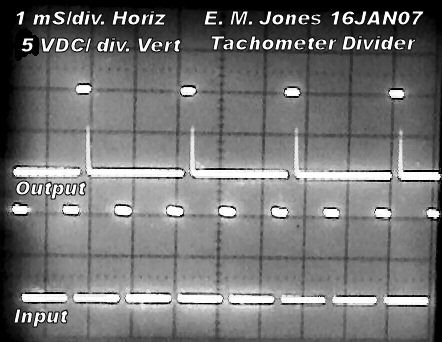
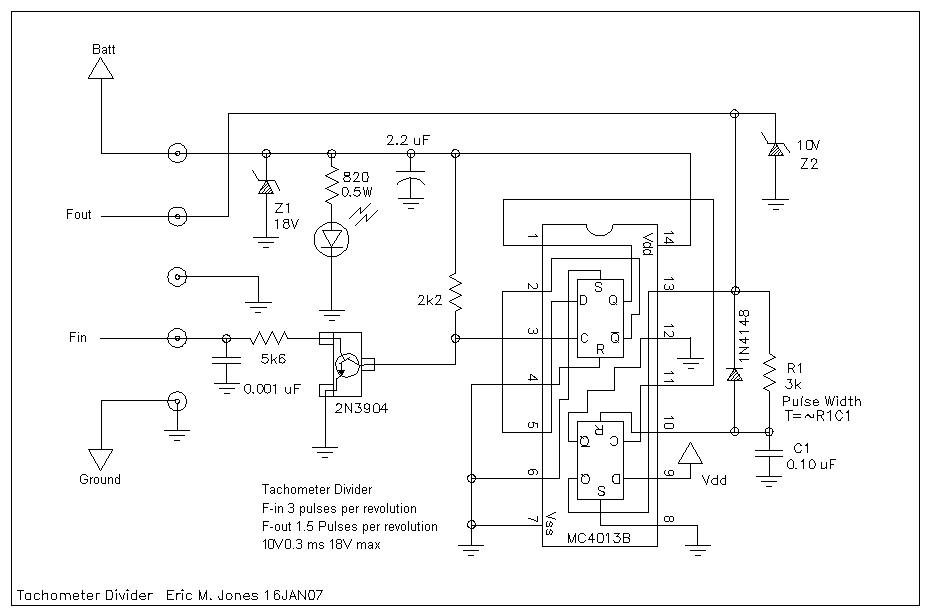
I wanted to repost a circuit that I built for an Aeroelectric lister for his problem of interfacing two different tach generators with one tachometer. This is a simple divide by two and signal conditioner that might prove useful in these, or related efforts.


I have PCBs for this and can build up one for little money.
| | - The Matronics AeroElectric-List Email Forum - | | | Use the List Feature Navigator to browse the many List utilities available such as the Email Subscriptions page, Archive Search & Download, 7-Day Browse, Chat, FAQ, Photoshare, and much more:
http://www.matronics.com/Navigator?AeroElectric-List |
|
| Description: |
|
| Filesize: |
31.36 KB |
| Viewed: |
8530 Time(s) |
|
| Description: |
|
| Filesize: |
67.65 KB |
| Viewed: |
8530 Time(s) |
|
_________________
Eric M. Jones
www.PerihelionDesign.com
113 Brentwood Drive
Southbridge, MA 01550
(508) 764-2072
emjones(at)charter.net |
|
| Back to top |
|
 |
|
|
You cannot post new topics in this forum
You cannot reply to topics in this forum
You cannot edit your posts in this forum
You cannot delete your posts in this forum
You cannot vote in polls in this forum
You cannot attach files in this forum
You can download files in this forum
|
Powered by phpBB © 2001, 2005 phpBB Group
|


