 |
Matronics Email Lists
Web Forum Interface to the Matronics Email Lists
|
| View previous topic :: View next topic |
| Author |
Message |
mdnanwelch7(at)hotmail.co
Guest
|
 Posted: Tue Apr 13, 2010 9:35 am Post subject: copper foil groundplane Posted: Tue Apr 13, 2010 9:35 am Post subject: copper foil groundplane |
 |
|
Hi guys,


  I've just joined this group and have a couple of questions.  I have searched the archives, but finding my particular answers is tough, to say the least.


  I'm getting very close to installing the Icom A200 comm antenna in my tube & fabric airplane (Kolb MkIII).  I think I've chosen to go underneath the fuselage, between the main gear legs, with the 23" steel rod mast pointing down and rearward.


Here's my first question;  is the center solid wire RG58 antenna lead the one that point down and away?  In other words, the shielding cable is the lead that I make the groundplane with, right?  I also assume they are NOT interchangeable, true?


  I can build a decent dipole antenna using a 1/8" welding rod using Dean Scott's design plans.  But, the groundplane rod of the dipole would be inside the steel frame fuselage, which isn't good.  I would include the Pawsey stub for the balun.


   Second question;  can I build a 1/2" copper tape "X" groundplane and attach it to the inside of the fabric at the center of the BNC connector.  If it's possible to use this style of groundplane with the solid rod antenna, can a guy use 6 legs of the copper foil?  Any advantage to more than just the (4) 23" strips?


 Thanks for your help!


 Mike Welch


 PS.  Here is the link to Dean Scott's antenna design I would probably be using.

 http://forums.matronics.com//files/antenna_design_118.pdf


 		 	   		  Hotmail is redefining busy with tools for the New Busy. Get more from your inbox. See how.  [quote][b]
| | - The Matronics AeroElectric-List Email Forum - | | | Use the List Feature Navigator to browse the many List utilities available such as the Email Subscriptions page, Archive Search & Download, 7-Day Browse, Chat, FAQ, Photoshare, and much more:
http://www.matronics.com/Navigator?AeroElectric-List |
|
|
|
| Back to top |
|
 |
doug.ilg(at)verizon.net
Guest
|
| Posted: Tue Apr 13, 2010 12:04 pm Post subject: copper foil groundplane |
|
|
Mike,
Have you looked at Miracle Antenna's Air Whip? http://www.miracleantenna.com/AirWhip.htm It's a full dipole antenna that's made completely of flexible wire. It's also end-fed, so you don't need access to the middle of the antenna for connection. You can put it anywhere in the fuselage that's not shielded by conductive parts.
I'm not flying yet, but mine seems to work very well on the ground. It fits quite well in the fiberglass nose cone of my Challenger. Based on a quick look at a picture of a Kolb M3X, I'd guess you could do something similar in your airplane. It might save you some of the hassle you're dealing with.
FYI.
-Doug
Doug Ilg
Grumman Tiger N74818, College Park Airport (KCGS), Maryland
Challenger II LSS LW (N641LG reserved) - kit underway at Laurel Suburban (W18)
| Quote: |
From: Mike Welch <mdnanwelch7(at)hotmail.com>
To: aeroelectric-list(at)matronics.com
Sent: Tue, April 13, 2010 1:15:25 PM
Subject: copper foil groundplane
Hi guys,
I've just joined this group and have a couple of questions. I have searched the archives, but finding my particular answers is tough, to say the least.
I'm getting very close to installing the Icom A200 comm antenna in my tube & fabric airplane (Kolb MkIII). I think I've chosen to go underneath the fuselage, between the main gear legs, with the 23" steel rod mast pointing down and rearward.
|
| | - The Matronics AeroElectric-List Email Forum - | | | Use the List Feature Navigator to browse the many List utilities available such as the Email Subscriptions page, Archive Search & Download, 7-Day Browse, Chat, FAQ, Photoshare, and much more:
http://www.matronics.com/Navigator?AeroElectric-List |
|
|
|
| Back to top |
|
|
mdnanwelch7(at)hotmail.co
Guest
|
| Posted: Tue Apr 13, 2010 1:48 pm Post subject: copper foil groundplane |
|
|
Doug,
No, I hadn't heard of this one. It sounds like this could be the perfect setup. Do you know how the wire is "oriented"? Can you just make a circular loop, or ????
I do like the idea of this antenna, but since I'm between jobs right now, funds are very scarce. Plus, I really wanted to make the antenna for my plane, just for the experience.
Does anyone know of a DIY plan for this type of dipole end-fed com antenna? What is in that little black box? (hopefully not some of that "special smoke" that leaks out when you touch two wrong wires together!!)
If anyone knows of a way to make one these single wire dipole end-fed antennas, I'd sure appreciate a drawing or two.
Thanks again, Doug, for the tip!!
Mike Welch
.ExternalClass DIV {;}
Mike,
Have you looked at Miracle Antenna's Air Whip? http://www.miracleantenna.com/AirWhip.htm It's a full dipole antenna that's made completely of flexible wire. It's also end-fed, so you don't need access to the middle of the antenna for connection. You can put it anywhere in the fuselage that's not shielded by conductive parts.
I'm not flying yet, but mine seems to work very well on the ground. It fits quite well in the fiberglass nose cone of my Challenger. Based on a quick look at a picture of a Kolb M3X, I'd guess you could do something similar in your airplane. It might save you some of the hassle you're dealing with.
FYI.
-Doug
Doug Ilg
Grumman Tiger N74818, College Park Airport (KCGS), Maryland
Challenger II LSS LW (N641LG reserved) - kit underway at Laurel Suburban (W18)
| Quote: |
From: Mike Welch <mdnanwelch7(at)hotmail.com>
To: aeroelectric-list(at)matronics.com
Sent: Tue, April 13, 2010 1:15:25 PM
Subject: copper foil groundplane
.ExternalClass .ecxhmmessage P {padding:0px;} .ExternalClass body.ecxhmmessage {font-size:10pt;font-family:Verdana;} Hi guys,
I've just joined this group and have a couple of questions. I have searched the archives, but finding my particular answers is tough, to say the least.
I'm getting very close to installing the Icom A200 comm antenna in my tube & fabric airplane (Kolb MkIII). I think I've chosen to go underneath the fuselage, between the main gear legs, with the 23" steel rod mast pointing down and rearward.
|
Hotmail is redefining busy with tools for the New Busy. Get more from your inbox. See how. [quote][b]
| | - The Matronics AeroElectric-List Email Forum - | | | Use the List Feature Navigator to browse the many List utilities available such as the Email Subscriptions page, Archive Search & Download, 7-Day Browse, Chat, FAQ, Photoshare, and much more:
http://www.matronics.com/Navigator?AeroElectric-List |
|
|
|
| Back to top |
|
|
nuckolls.bob(at)aeroelect
Guest
|
| Posted: Tue Apr 13, 2010 8:30 pm Post subject: copper foil groundplane |
|
|
At 01:15 PM 4/13/2010, you wrote:

 Mike,


 Have you looked at Miracle Antenna's Air Whip?   http://www.miracleantenna.com/AirWhip.htm  It's a full dipole antenna that's made completely of flexible wire.  It's also end-fed, so you don't need access to the middle of the antenna for connection.  You can put it anywhere in the fuselage that's not shielded by conductive parts.


 I'm not flying yet, but mine seems to work very well on the ground.  It fits quite well in the fiberglass nose cone of my Challenger.  Based on a quick look at a picture of a Kolb M3X, I'd guess you could do something similar in your airplane.  It might save you some of the hassle you're dealing with.


     The end-fed half-wave antenna has been around

     for a long time and is a popular topic of

     discussion and debate in the amateur radio

     antenna forums. There's a particularly lucid

     study of these beasties to be found at:


  http://www.aa5tb.com/efha.html


     Of course, this article is dealing with the lower

     HF frequencies of interest to amateurs but the

     physics scales nicely into the higher VHF range.


     My sense is that while they can be "tuned" to

     accommodate effects of installation, they're not

     your grandpa's plug-n-play buggy whip. It's unlikely

     that an end-fed half-wave stuck inside the fuselage

     of a composite aircraft will be optimized out of the

     box for that particular installation.


     Having said that, we also know that antenna efficiency

     in airplanes can be all over the map and still provide

     satisfactory performance. I have no doubt that the

     antenna offered has many "satisfied" users.


     If the builder is not DIY shy, a few dollars in

     materials can be crafted into an quarter-wave

     over ground-plane antenna that will certainly

     perform as well with more predictable results

     for SWR. Getting to the center of a half-wave

     dipole isn't hard if you put the center

     half way up on the side of the fuselage and

     wrap around the inside surface.


     Distorting from a straight antenna will have

     the effect of electrically lengthening the

     antenna so trimming after installation with

     some form of SWR instrument would be useful

     . . . but probably wouldn't produce observable

     differences in performance


 [/b]I've just joined this group and have a couple of questions.

 I have searched the archives, but finding my particular

 answers is tough, to say the least. I'm getting very close to

 installing the Icom A200 comm antenna in my tube & fabric

 airplane (Kolb MkIII).  I think I've chosen to go underneath

 the fuselage, between the main gear legs, with the 23" steel

 rod mast pointing down and rearward.


    That will probably work as well as anything else.

    You can ground the feedline shield to the steel-tube

    structure.


    Bob . . .


 [/b]


     [quote][b]
| | - The Matronics AeroElectric-List Email Forum - | | | Use the List Feature Navigator to browse the many List utilities available such as the Email Subscriptions page, Archive Search & Download, 7-Day Browse, Chat, FAQ, Photoshare, and much more:
http://www.matronics.com/Navigator?AeroElectric-List |
|
|
|
| Back to top |
|
|
mdnanwelch7(at)hotmail.co
Guest
|
| Posted: Wed Apr 14, 2010 5:14 am Post subject: copper foil groundplane |
|
|
Hi Bob,
Thanks for the detailed and informative response. Yes, I am very much a DIY person.
I don't really have the $100 for the Miracle antenna (end-fed halfwave dipole), so I guess I'll have to stick with a homemade one.
So far, I'm still leaning toward the belly mount dipole, and making a spoke style grid of copper foil, where the steel rod mast mounts in the center of the grid. I'll sure to get a good ground of the groundplane to the tube frame.
Does more than four legs of a cu foil groundplane make it better? Or, is that just a waste of copper tape?
I'm curious. After I get this antenna constructed, mounted and finished, how does one check it's adjustment with a SWR meter. I mean, there aren't many things you could do to the mast, except cut off a little. But, what if you cut off too much?
Could you possibly explain the actual nuts and bolts of using an SWR meter, and how it can allow a guy to improve his antenna's performance?
One more thing.... I am also building a GlaStar, and bought the factory copper foil dipole antenna. I noticed it has triax cable, rather than regular RG58. I assume this is because the extra layer of the triax acts as a balun. I meant to check out how the triax connects at the junction of the two copper strips, but forgot, and mounted it in the tail and closed it up.
For fiberglass airplanes that might use this type of "triax cable copper foil dipole", how and where is the triax soldered, if it's soldered at all?
Thanks a lot!!
Mike Welch
The end-fed half-wave antenna has been around
for a long time and is a popular topic of
discussion and debate in the amateur radio
antenna forums. There's a particularly lucid
study of these beasties to be found at:
http://www.aa5tb.com/efha.html
Of course, this article is dealing with the lower
HF frequencies of interest to amateurs but the
physics scales nicely into the higher VHF range.
My sense is that while they can be "tuned" to
accommodate effects of installation, they're not
your grandpa's plug-n-play buggy whip. It's unlikely
that an end-fed half-wave stuck inside the fuselage
of a composite aircraft will be optimized out of the
box for that particular installation.
Having said that, we also know that antenna efficiency
in airplanes can be all over the map and still provide
satisfactory performance. I have no doubt that the
antenna offered has many "satisfied" users.
If the builder is not DIY shy, a few dollars in
materials can be crafted into an quarter-wave
over ground-plane antenna that will certainly
perform as well with more predictable results
for SWR. Getting to the center of a half-wave
dipole isn't hard if you put the center
half way up on the side of the fuselage and
wrap around the inside surface.
Distorting from a straight antenna will have
the effect of electrically lengthening the
antenna so trimming after installation with
some form of SWR instrument would be useful
. . . but probably wouldn't produce observable
differences in performance
[/b]I've just joined this group and have a couple of questions.
I have searched the archives, but finding my particular
answers is tough, to say the least. I'm getting very close to
installing the Icom A200 comm antenna in my tube & fabric
airplane (Kolb MkIII). I think I've chosen to go underneath
the fuselage, between the main gear legs, with the 23" steel
rod mast pointing down and rearward.
That will probably work as well as anything else.
You can ground the feedline shield to the steel-tube
structure.
Bob . . .
[/b]
| Quote: |
-List">http://www.matronics.com/Navigator?AeroElectric-List
ronics.com
ww.matronics.com/contribution
|
The New Busy think 9 to 5 is a cute idea. Combine multiple calendars with Hotmail. Get busy. [quote][b]
| | - The Matronics AeroElectric-List Email Forum - | | | Use the List Feature Navigator to browse the many List utilities available such as the Email Subscriptions page, Archive Search & Download, 7-Day Browse, Chat, FAQ, Photoshare, and much more:
http://www.matronics.com/Navigator?AeroElectric-List |
|
|
|
| Back to top |
|
|
N20DG
Joined: 02 Jan 2008
Posts: 61
Location: lancaster, texas
|
| Posted: Wed Apr 14, 2010 6:26 am Post subject: copper foil groundplane |
|
|
Check this out
http://rst-engr.com/rst/catalog/airplane_antenna.html
Dick
In a message dated 4/14/2010 8:16:26 A.M. Central Daylight Time, mdnanwelch7(at)hotmail.com writes:
| Quote: | Hi Bob,
Thanks for the detailed and informative response. Yes, I am very much a DIY person.
I don't really have the $100 for the Miracle antenna (end-fed halfwave dipole), so I guess I'll have to stick with a homemade one.
So far, I'm still leaning toward the belly mount dipole, and making a spoke style grid of copper foil, where the steel rod mast mounts in the center of the grid. I'll sure to get a good ground of the groundplane to the tube frame.
Does more than four legs of a cu foil groundplane make it better? Or, is that just a waste of copper tape?
I'm curious. After I get this antenna constructed, mounted and finished, how does one check it's adjustment with a SWR meter. I mean, there aren't many things you could do to the mast, except cut off a little. But, what if you cut off too much?
Could you possibly explain the actual nuts and bolts of using an SWR meter, and how it can allow a guy to improve his antenna's performance?
One more thing.... I am also building a GlaStar, and bought the factory copper foil dipole antenna. I noticed it has triax cable, rather than regular RG58. I assume this is because the extra layer of the triax acts as a balun. I meant to check out how the triax connects at the junction of the two copper strips, but forgot, and mounted it in the tail and closed it up.
For fiberglass airplanes that might use this type of "triax cable copper foil dipole", how and where is the triax soldered, if it's soldered at all?
Thanks a lot!!
Mike Welch
The end-fed half-wave antenna has been around
for a long time and is a popular topic of
discussion and debate in the amateur radio
antenna forums. There's a particularly lucid
study of these beasties to be found at:
http://www.aa5tb.com/efha.html
Of course, this article is dealing with the lower
HF frequencies of interest to amateurs but the
physics scales nicely into the higher VHF range.
My sense is that while they can be "tuned" to
accommodate effects of installation, they're not
your grandpa's plug-n-play buggy whip. It's unlikely
that an end-fed half-wave stuck inside the fuselage
of a composite aircraft will be optimized out of the
box for that particular installation.
Having said that, we also know that antenna efficiency
in airplanes can be all over the map and still provide
satisfactory performance. I have no doubt that the
antenna offered has many "satisfied" users.
If the builder is not DIY shy, a few dollars in
materials can be crafted into an quarter-wave
over ground-plane antenna that will certainly
perform as well with more predictable results
for SWR. Getting to the center of a half-wave
dipole isn't hard if you put the center
half way up on the side of the fuselage and
wrap around the inside surface.
Distorting from a straight antenna will have
the effect of electrically lengthening the
antenna so trimming after installation with
some form of SWR instrument would be useful
. . . but probably wouldn't produce observable
differences in performance
[/b]I've just joined this group and have a couple of questions.
I have searched the archives, but finding my particular
answers is tough, to say the least. I'm getting very close to
installing the Icom A200 comm antenna in my tube & fabric
airplane (Kolb MkIII). I think I've chosen to go underneath
the fuselage, between the main gear legs, with the 23" steel
rod mast pointing down and rearward.
That will probably work as well as anything else.
You can ground the feedline shield to the steel-tube
structure.
Bob . . .
[/b]
| Quote: |
-List">http://www.matronics.com/Navigator?AeroElectric-List
ronics.com
ww.matronics.com/contribution
|
The New Busy think 9 to 5 is a cute idea. Combine multiple calendars with Hotmail. Get busy. | Quote: |
====================================
List href="http://www.matronics.com/Navigator?AeroElectric-List">http://www.matronics.com/Navigator?AeroElectric-List
====================================
ms.matronics.com/">http://forums.matronics.com
====================================
tp://www.matronics.com/contribution">http://www.matronics.com/contribution
====================================
|
|
[quote][b]
| | - The Matronics AeroElectric-List Email Forum - | | | Use the List Feature Navigator to browse the many List utilities available such as the Email Subscriptions page, Archive Search & Download, 7-Day Browse, Chat, FAQ, Photoshare, and much more:
http://www.matronics.com/Navigator?AeroElectric-List |
|
|
|
| Back to top |
|
|
mdnanwelch7(at)hotmail.co
Guest
|
| Posted: Wed Apr 14, 2010 7:35 am Post subject: copper foil groundplane |
|
|
Dick,
I'm very familiar with Bob Weir's stuff, and in fact, I built one of these copper foil antennas a few years ago. I haven't installed it yet. If I can find it, I think I'm going to go ahead and use it.
I built the mast out of fiberglass, with the copper foil sandwiched inside it. The mast is then soldered to a BNC connector, and faired in with more fiberglass. Finally, I sanded everything nice and smooth, and painted it grey.
Thanks for the reference, tho.
Mike Welch
From: RGent1224(at)aol.com
Date: Wed, 14 Apr 2010 10:19:48 -0400
Subject: Re: RE: copper foil groundplane
To: aeroelectric-list(at)matronics.com
Check this out
http://rst-engr.com/rst/catalog/airplane_antenna.html
Dick
In a message dated 4/14/2010 8:16:26 A.M. Central Daylight Time, mdnanwelch7(at)hotmail.com writes:
| Quote: | Hi Bob,
Thanks for the detailed and informative response. Yes, I am very much a DIY person.
I don't really have the $100 for the Miracle antenna (end-fed halfwave dipole), so I guess I'll have to stick with a homemade one.
So far, I'm still leaning toward the belly mount dipole, and making a spoke style grid of copper foil, where the steel rod mast mounts in the center of the grid. I'll sure to get a good ground of the groundplane to the tube frame.
Does more than four legs of a cu foil groundplane make it better? Or, is that just a waste of copper tape?
I'm curious. After I get this antenna constructed, mounted and finished, how does one check it's adjustment with a SWR meter. I mean, there aren't many things you could do to the mast, except cut off a little. But, what if you cut off too much?
Could you possibly explain the actual nuts and bolts of using an SWR meter, and how it can allow a guy to improve his antenna's performance?
One more thing.... I am also building a GlaStar, and bought the factory copper foil dipole antenna. I noticed it has triax cable, rather than regular RG58. I assume this is because the extra layer of the triax acts as a balun. I meant to check out how the triax connects at the junction of the two copper strips, but forgot, and mounted it in the tail and closed it up.
For fiberglass airplanes that might use this type of "triax cable copper foil dipole", how and where is the triax soldered, if it's soldered at all?
Thanks a lot!!
Mike Welch
The end-fed half-wave antenna has been around
for a long time and is a popular topic of
discussion and debate in the amateur radio
antenna forums. There's a particularly lucid
study of these beasties to be found at:
http://www.aa5tb.com/efha.html
Of course, this article is dealing with the lower
HF frequencies of interest to amateurs but the
physics scales nicely into the higher VHF range.
My sense is that while they can be "tuned" to
accommodate effects of installation, they're not
your grandpa's plug-n-play buggy whip. It's unlikely
that an end-fed half-wave stuck inside the fuselage
of a composite aircraft will be optimized out of the
box for that particular installation.
Having said that, we also know that antenna efficiency
in airplanes can be all over the map and still provide
satisfactory performance. I have no doubt that the
antenna offered has many "satisfied" users.
If the builder is not DIY shy, a few dollars in
materials can be crafted into an quarter-wave
over ground-plane antenna that will certainly
perform as well with more predictable results
for SWR. Getting to the center of a half-wave
dipole isn't hard if you put the center
half way up on the side of the fuselage and
wrap around the inside surface.
Distorting from a straight antenna will have
the effect of electrically lengthening the
antenna so trimming after installation with
some form of SWR instrument would be useful
. . . but probably wouldn't produce observable
differences in performance
[/b]I've just joined this group and have a couple of questions.
I have searched the archives, but finding my particular
answers is tough, to say the least. I'm getting very close to
installing the Icom A200 comm antenna in my tube & fabric
airplane (Kolb MkIII). I think I've chosen to go underneath
the fuselage, between the main gear legs, with the 23" steel
rod mast pointing down and rearward.
That will probably work as well as anything else.
You can ground the feedline shield to the steel-tube
structure.
Bob . . .
[/b]
| Quote: |
-List">http://www.matronics.com/Navigator?AeroElectric-List
ronics.com
ww.matronics.com/contribution
|
The New Busy think 9 to 5 is a cute idea. Combine multiple calendars with Hotmail. Get busy. |
| Quote: |
-List">http://www.matronics.com/Navigator?AeroElectric-List
ronics.com
ww.matronics.com/contribution
|
The New Busy think 9 to 5 is a cute idea. Combine multiple calendars with Hotmail. Get busy. [quote][b]
| | - The Matronics AeroElectric-List Email Forum - | | | Use the List Feature Navigator to browse the many List utilities available such as the Email Subscriptions page, Archive Search & Download, 7-Day Browse, Chat, FAQ, Photoshare, and much more:
http://www.matronics.com/Navigator?AeroElectric-List |
|
|
|
| Back to top |
|
|
nuckolls.bob(at)aeroelect
Guest
|
| Posted: Wed Apr 14, 2010 7:48 am Post subject: copper foil groundplane |
|
|
At 08:12 AM 4/14/2010, you wrote:

 Hi Bob,


 Thanks for the detailed and informative response.  Yes, I am very

 much a DIY person. I don't really have the $100 for the Miracle

 antenna (end-fed halfwave dipole), so I guess I'll have to stick with

 a homemade one.


    I've had an antenna building article on my to-do list

    for years. Unfortunately that list is long and the

    antenna project is pretty far down. Suggest you start

    with a manufactured "mount" like . . . .


     http://tinyurl.com/y3a4lpf


    This is an example of MANY similar products which

    you can find at about any truck-stop on a major highway.

    You can install the mating PL-259 coax connector

    on your coax -OR- install a SO Male to BNC female

    adapter to mate with your own installed BNC cable

    male -OR- consider this pre-mfg assembly from

    Radio Shack . . .


     http://tinyurl.com/y7dzxpf


    It has a PL-259 on one end that will mate with

    your "truckers antenna mount". You can cut the

    connector off the other end and install a cable

    male to mate with your transceiver.


 So far, I'm still leaning toward the belly mount dipole,


    "dipole" or "vertical 1/4-wave"?


 and making a spoke style grid of copper foil, where the steel rod

 mast mounts in the center of the grid.  I'll sure to get a good ground

 of the groundplane to the tube frame.  Does more than four legs of

 a cu foil groundplane make it better?  Or, is that just a waste of

 copper tape?


    Tests have shown that there's a diminishing return

    on investment for adding radials to the ground plane.

    To make a significant improvement one needs to double

    the radials. The step from 4 is up to 8 . . . you can

    see where that's taking us.


    You'll need some sort of structural bracket

    that grips a tube and supplies a suitable

    flat against the inside surface of the fabric

    for attaching the antenna. This bracket also be

    suitable for grounding the coax shield to the

    airframe. Getting  robust connection to a ground

    plane attached inside a fabric 'skin' is problematic.

    The ship's existing metallic structure is a

    reasonable substitute for the classic "spider

    legs" ground plane.


 I'm curious.  After I get this antenna constructed, mounted and finished,

 how does one check it's adjustment with a SWR meter.  I mean, there

 aren't many things you could do to the mast, except cut off a little.


    Correct. If you were going to "go for the gold",

    you'd make it extra long by about an inch and

    then trim to length for best SWR at the selected

    center frequency.  The theroetical 1/4-wave centered

    in the VHF comm band (129.5 Mhz) is 23.34 inches.

    If you cut it to 22.34 inches the antenna is

    calculated to center on  132.14 Mhz. So the

    "tuning sensitivity" for this antenna is on the

    order of 2.6 Mhz per inch of length. So trimming

    say .1" at a time would let you "sneak up on it".


    Alternatively, you can calculate a new length based

    on measured center frequency using the 2.6"/MHz

    sensitivity factor.


    Now that we've fine tuned the theory, know also

    that there are other factors that influence the

    resonant frequency. An important one is a correction

    for length/diameter ratio. I speak to this effect

    in figure 13-6 of the 'Connection. If your antenna

    rod is .125" diam stainless and is about 23" long,

    then the l/d ratio is about 160. This translates

    to an electrical "lengthening" of about 3.5% or

    .81 inches. Gee, this translates to about 2 Mhz

    shift in center frequency.


    Further, bending your antenna aft for a rakish

    appearance (or better ground clearance) has a

    further lengthening effect. All this calculator

    key-punching goes to demonstrate that the ideal

    antenna is trimmed to length after installation

    using some form of instrumentation.


    Return on investment? The guy listening to your

    transmitted signal wouldn't know the difference

    between the "ideal" and "pretty close" antenna.

    Further, DIRECTIONAL effects of airframe geometry

    can have a PROFOUND effect on the very best of

    antennas. This effect is discussed in the BALUN

    construction article cited below.


    Bottom line: 22" for a 1/4-wave stick is close

    enough for government work. An SWR test at the

    transceiver  end of the feed line is most useful

    as a gross check of antenna integrity. Check SWR

    at say 1 Mhz steps from 118.0 to 135.0 and plot the

    results. The "dip" in the plot shows the center

    frequency of the antenna. The SWR shouldn't be

    more than 3.0:1 over the full range of interest.


    An antenna with a broken connection along the feed

    line will have very high SWR numbers and probably

    exhibit no clear "dip" in the plot.


 But, what if you cut off too much?


    That IS a problem only if you're pedantic about

    getting the antenna performance centered on

    129.5000000000 Mhz. If you "overshoot" a trimming

    operation and the durn thing now centers at 131

    Mhz, no big deal.


 Could you possibly explain the actual nuts and bolts of using

 an SWR meter, and how it can allow a guy to improve his antenna's

 performance?


    It's pretty simple. Use your ship's transmitter

    as a signal source and plot measured SWR against

    transmit frequency. When you're all done, the

    SWR will be LOWEST at the design center. SWR

    should not be more than 3:1 at the edges of

    the band.


 One more thing....  I am also building a GlaStar, and bought the

 factory copper foil dipole antenna.  I noticed it has triax cable,

 rather than regular RG58.  I assume this is because the extra layer

 of the triax acts as a balun.  I meant to check out how the triax

 connects at the junction of the two copper strips, but forgot, and

 mounted it in the tail and closed it up.


 For fiberglass airplanes that might use this type of "triax cable

 copper foil dipole", how and where is the triax soldered, if it's

 soldered at all?


    I've heard of this design but never had the opportunity

    to run it through the lab. It's better than NO balun but

    again, ROI is problematic. The outer shield could be

    used two ways: Soldered to the inner shield 1/4-wave from

    the antenna end only. This makes it a "bazooka" decoupling

    sleeve.


     http://tinyurl.com/y6xgese


    Alternatively, it can solder to the inner shield 1/4-wave

    away from the antenna as above. The other end of outer

    shield solders to the center conductor at the antenna

    end. This makes it a piece of transmission line. This

    type of balun is easily synthesized without the use

    of triaxial coax as shown here:


     http://tinyurl.com/yytxwd3


    I wouldn't discourage anyone from going for the best-

    we-know-how-to-do in selection/fabrication, installation

    and testing of antennas on the airplane. At the same

    time, know that "missing the mark" by some small amount

    is probably not a reason for ripping it out and starting

    over.


       Bob . . .


     [quote][b]
| | - The Matronics AeroElectric-List Email Forum - | | | Use the List Feature Navigator to browse the many List utilities available such as the Email Subscriptions page, Archive Search & Download, 7-Day Browse, Chat, FAQ, Photoshare, and much more:
http://www.matronics.com/Navigator?AeroElectric-List |
|
|
|
| Back to top |
|
|
n81jg(at)aol.com
Guest
|
| Posted: Wed Apr 14, 2010 10:02 am Post subject: copper foil groundplane |
|
|
Check out Slim Jim and J-pole antennas on Google. They are end fed dipoles.


 John Greaves

 VariEze N81JG

 Redding, CA


  --
| | - The Matronics AeroElectric-List Email Forum - | | | Use the List Feature Navigator to browse the many List utilities available such as the Email Subscriptions page, Archive Search & Download, 7-Day Browse, Chat, FAQ, Photoshare, and much more:
http://www.matronics.com/Navigator?AeroElectric-List |
|
|
|
| Back to top |
|
|
longg(at)pjm.com
Guest
|
| Posted: Wed Apr 14, 2010 10:44 am Post subject: copper foil groundplane |
|
|
Found this. Just put in the freq and it tells you how long to make it.

Does that mean the length we're shooting for is the middle of the band?


http://www.m0ukd.com/Calculators/Slim_Jim/index.php


Glenn


--
| | - The Matronics AeroElectric-List Email Forum - | | | Use the List Feature Navigator to browse the many List utilities available such as the Email Subscriptions page, Archive Search & Download, 7-Day Browse, Chat, FAQ, Photoshare, and much more:
http://www.matronics.com/Navigator?AeroElectric-List |
|
|
|
| Back to top |
|
|
checkn6
Joined: 20 Feb 2010
Posts: 14
|
| Posted: Wed Apr 14, 2010 1:32 pm Post subject: Re: copper foil groundplane |
|
|
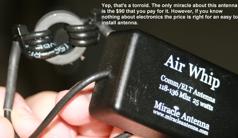
Inside the magic box
| | - The Matronics AeroElectric-List Email Forum - | | | Use the List Feature Navigator to browse the many List utilities available such as the Email Subscriptions page, Archive Search & Download, 7-Day Browse, Chat, FAQ, Photoshare, and much more:
http://www.matronics.com/Navigator?AeroElectric-List |
|
| Description: |
|
| Filesize: |
53.02 KB |
| Viewed: |
10972 Time(s) |
|
|
|
| Back to top |
|
|
longg(at)pjm.com
Guest
|
| Posted: Thu Apr 15, 2010 5:56 am Post subject: copper foil groundplane |
|
|
Thanks,


Actually I'd pay $90 just for the packaging. I've now seen some of the

homemade jobs and while I've not clue on how to build antennas, I have

less of clue how any of these folks got their inventions in the

airplane. Copper strips, pipe, soldering, 3 ft tall, etc. etc. I have a

Lancair not a Suburban.


$90.00 is a no brainer. Thanks for the reference.


Do Not Archive.


Glenn


--
| | - The Matronics AeroElectric-List Email Forum - | | | Use the List Feature Navigator to browse the many List utilities available such as the Email Subscriptions page, Archive Search & Download, 7-Day Browse, Chat, FAQ, Photoshare, and much more:
http://www.matronics.com/Navigator?AeroElectric-List |
|
|
|
| Back to top |
|
|
|
|
You cannot post new topics in this forum
You cannot reply to topics in this forum
You cannot edit your posts in this forum
You cannot delete your posts in this forum
You cannot vote in polls in this forum
You cannot attach files in this forum
You can download files in this forum
|
Powered by phpBB © 2001, 2005 phpBB Group
|

