 |
Matronics Email Lists
Web Forum Interface to the Matronics Email Lists
|
| View previous topic :: View next topic |
| Author |
Message |
Chris_A
Joined: 20 Jun 2010
Posts: 20
Location: Mustang OK
|
 Posted: Sat Aug 07, 2010 8:00 pm Post subject: Acceptable horizontal stabilizer adjustment Posted: Sat Aug 07, 2010 8:00 pm Post subject: Acceptable horizontal stabilizer adjustment |
 |
|
Hi guys,
Iâm in the process of completing my tail boom rebuild and in fact nearly done. I have taken lots of pictures and will share my experience with the project shortly. However, this evening I was installing the horizontal stabilizers and even though I spent two hours making sure I had the proper center line on the boom I still managed to get the tail assembly slightly canted (counter clockwise of center). And by slightly I mean 2â difference from the far left edge to the far right edge of the horizontal stabilizers (outside to outside). The holes are drilled and rivets set so there is no going back. I have read through the original Firestar manual and page 12 paragraph one reads:
ââ¦Now check to see if the horizontal stabilizers are level and perpendicular to the vertical stabilizers. Also check to see if the top and bottom vertical stabilizers are straight [in-line] with each other. Adjust the cables by tightening one and releasing another until all the above conditions are met. It may take a fair amount of adjusting and re-adjusting to get everything in proper alignmentâ¦â
Now as you have probably figured out this also means the vertical stabilizer is also canted. It is. The top edge is a .5â counter clockwise (left) of center, center being the drive shaft on the gear box. This seems easily corrected by adjusting the cables.
My concern is the horizontal stabilizers, is adjusting the left side down one inch and raising the right side one inch acceptable?
Other than this everything is dead on. I do realize this is the most important thing to not screw up.
If you are wondering I did install the H-brace and boom to the cage first. My thinking was that it would be easier to have the boom on the plane before assembling the tail.
Thanks,
Chris
| | - The Matronics Kolb-List Email Forum - | | | Use the List Feature Navigator to browse the many List utilities available such as the Email Subscriptions page, Archive Search & Download, 7-Day Browse, Chat, FAQ, Photoshare, and much more:
http://www.matronics.com/Navigator?Kolb-List |
|
|
|
| Back to top |
|
 |
racerjerry
Joined: 15 Dec 2009
Posts: 202
Location: Deer Park, NY
|
| Posted: Sun Aug 08, 2010 3:56 am Post subject: Re: Acceptable horizontal stabilizer adjustment |
|
|
Shhhhh. Level the horizontal stabilizers and no one will know except you. Fabricate new cables if required. In case anyone should discover that your vertical stabilizer is slightly out of alignment, make up a good lie ahead of time about the time you got caught in a thunderstorm and the boom got twisted.
| | - The Matronics Kolb-List Email Forum - | | | Use the List Feature Navigator to browse the many List utilities available such as the Email Subscriptions page, Archive Search & Download, 7-Day Browse, Chat, FAQ, Photoshare, and much more:
http://www.matronics.com/Navigator?Kolb-List |
|
_________________
Jerry King |
|
| Back to top |
|
|
mdnanwelch7(at)hotmail.co
Guest
|
| Posted: Sun Aug 08, 2010 5:48 am Post subject: Acceptable horizontal stabilizer adjustment |
|
|
> The holes are drilled and rivets set so there is no going back.

 > Thanks, Chris


Chris,


   Sorry to hear about the screw up, but there ain't no such thing as

 no such thing!!  If it were me, yes, I'd absolutely drill out the rivets,

 and align it correctly.  How long would it take to drill them out?

 15  minutes???


   I'd redo it.


   After I got the assembly lined up properly, I would drill about 4 brand

 new holes, to lock the new position in place.

   After installing of the 4 locating rivets, I would;

  1) drill out all the remaining rivet holes to their next size UP!  They are

 probably 1/8" rivets, so I'd drill all the remaining holes to 3/16".  If you

 don't have any 3/16" rivets, order some, install them, and that's the only

 telltale sign of an error (no one else would know the difference)


   Yeah, I know a guy could fabricate some new cables, and bend the crap out

 the whole arrangement to make it look "close enough", and come up with lots

 of excuses that nobody really believes, OR, a guy could spend two hours and

 make it knat's a.. perfect, and not have to make any excuses.


 Just my opinion, other's may look at it a little differently.


   Remember;  a successful builder NEVER makes mistakes......only prototypes!!


 Mike Welch

 MkIII CX

 Finally back to work on my plane, after a 3 month hiatus to complete my house.

 Worked on my center console, new panel yesterday.


 		 	   		    [quote][b]
| | - The Matronics Kolb-List Email Forum - | | | Use the List Feature Navigator to browse the many List utilities available such as the Email Subscriptions page, Archive Search & Download, 7-Day Browse, Chat, FAQ, Photoshare, and much more:
http://www.matronics.com/Navigator?Kolb-List |
|
|
|
| Back to top |
|
|
Chris_A
Joined: 20 Jun 2010
Posts: 20
Location: Mustang OK
|
| Posted: Sun Aug 08, 2010 6:23 am Post subject: Re: Acceptable horizontal stabilizer adjustment |
|
|
I have thought about drilling out the rivets the only issue is that at the ring the adjustment would be so slight that I'm afraid I wouldn't have the right amount of clearance between the old holes and the new or even be able to drill the new holes without breaking into the old. And turning the end of the tube into Swiss cheese doesn't sound good either.


I have considered cutting an inch or so off the end and starting fresh but that would leave me with double holes on the other attachment points.
| | - The Matronics Kolb-List Email Forum - | | | Use the List Feature Navigator to browse the many List utilities available such as the Email Subscriptions page, Archive Search & Download, 7-Day Browse, Chat, FAQ, Photoshare, and much more:
http://www.matronics.com/Navigator?Kolb-List |
|
|
|
| Back to top |
|
|
mdnanwelch7(at)hotmail.co
Guest
|
| Posted: Sun Aug 08, 2010 6:53 am Post subject: Acceptable horizontal stabilizer adjustment |
|
|
| Quote: | I am still looking at drilling out the rivets the only issue is that at the ring the adjustment would be so slight that I'm afraid I wouldn't have the right amount of clearance
>Chris
|
Chris,
I know what you are referring to, but that's why I suggested the solution in the order I did.
The 4 new rivets would be at a place that hadn't ever been drilled before....brand new holes!!
These have the only function of locking the ring in it's proper orientation...period! Once the
ring is correct positioned, these rivets would go on immediately.
Yes, I know the old boomtube holes will be only slightly offset from the empennage ring,
but that's why I suggested the "next size up" after all the rivets were removed. That would take
care of that.
I'd bet the offset is so small, you'd barely be able to see it, which is my point about the next
size larger rivet. But, since you'd have the ring PERFECTly located at this point, and locked
in place with 4 rivets, you could drill all the remaining holes 3/16" and be creating the nice,
clean, tight hole for those 3/16" rivets. I don't know you get to the swiss cheese scenario.
On my list of screw-ups, this one wouldn't even break a sweat at fixing it right. But, you do
what you feel most comfortable with. Best of luck.
Mike W
[quote][b]
| | - The Matronics Kolb-List Email Forum - | | | Use the List Feature Navigator to browse the many List utilities available such as the Email Subscriptions page, Archive Search & Download, 7-Day Browse, Chat, FAQ, Photoshare, and much more:
http://www.matronics.com/Navigator?Kolb-List |
|
|
|
| Back to top |
|
|
Chris_A
Joined: 20 Jun 2010
Posts: 20
Location: Mustang OK
|
| Posted: Sun Aug 08, 2010 7:07 am Post subject: Re: Acceptable horizontal stabilizer adjustment |
|
|
I see now what you are saying. Drill four new locating holes through the ring and tube. Then drill out the existing holes. This sounds like a solution to my problem.


Thanks

Chris
| | - The Matronics Kolb-List Email Forum - | | | Use the List Feature Navigator to browse the many List utilities available such as the Email Subscriptions page, Archive Search & Download, 7-Day Browse, Chat, FAQ, Photoshare, and much more:
http://www.matronics.com/Navigator?Kolb-List |
|
|
|
| Back to top |
|
|
slyck(at)frontiernet.net
Guest
|
| Posted: Sun Aug 08, 2010 8:10 am Post subject: Acceptable horizontal stabilizer adjustment |
|
|
I see Mike smacking his forehead now 
Drill out the old rivets. Offset to the the previously quoted "perfect" position. If what Mike is saying is true, the holes won't be off by much.
In his case the larger rivet will do the trick. -If it still looks to be too much error for this approach you can use a (very) small rat tail or round file
to begin the larger hole in the ring, thereby beginning an offset that would be a better guide to the tube hole. Then clean it up with the right drill size.
BB
On 8, Aug 2010, at 11:07 AM, Chris_A wrote:
| | - The Matronics Kolb-List Email Forum - | | | Use the List Feature Navigator to browse the many List utilities available such as the Email Subscriptions page, Archive Search & Download, 7-Day Browse, Chat, FAQ, Photoshare, and much more:
http://www.matronics.com/Navigator?Kolb-List |
|
|
|
| Back to top |
|
|
Richard Pike

Joined: 09 Jan 2006
Posts: 1671
Location: Blountville, Tennessee
|
| Posted: Sun Aug 08, 2010 11:29 am Post subject: Re: Acceptable horizontal stabilizer adjustment |
|
|
You might not even need to go to 3/16" rivets, you might even be able to get by with 5/32" rivets. And it wouldn't hurt to drill the hole to 5/32" and see what it looked like, if it doesn't look sufficient, go to 3/16".


Richard Pike

MKIII N420P (420ldPoops)
| | - The Matronics Kolb-List Email Forum - | | | Use the List Feature Navigator to browse the many List utilities available such as the Email Subscriptions page, Archive Search & Download, 7-Day Browse, Chat, FAQ, Photoshare, and much more:
http://www.matronics.com/Navigator?Kolb-List |
|
|
|
| Back to top |
|
|
mdnanwelch7(at)hotmail.co
Guest
|
| Posted: Sun Aug 08, 2010 12:12 pm Post subject: Acceptable horizontal stabilizer adjustment |
|
|
> You might not even need to go to 3/16" rivets, you might even be able to get by with 5/32" rivets. And it wouldn't hurt to drill the hole to 5/32" and see what it looked like, if it doesn't look sufficient, go to 3/16".
| Quote: |
Richard Pike
MKIII N420P (420ldPoops)
|
Richard,
Yeah, I forgot about 5/32 rivets. I think you're probably right, the offset is likely to be
so small that a cleanup with a 5/32nd drilbit would take care of everything.
While we're talking about rivets and such, the fact of the matter is I'd probably use those 5/32"
DRIVEN rivets. Why not? You've got pretty good access for your bucking bar. I know pop
rivets could work, but if I was doing what Chris needs to do, I'd just drive the rivets.
Especially considering the fact I have all the proper pneumatic stuff (rivet gun and loads of
bucking bars) and a gazillion drive rivets. FWIW.
At any rate, that's what I'd do.
I spent the day out in my shop (finally) fabricating the center radio console. Hot and
humid as heck. Center console will have the Garmin 296 (w/ panel dock), King transponder,
Icom A200 com radio, and Dynon D10A EFIS. The panel that runs along the front of the
windscreen will have the rest of the instruments (like airspeed, rate of climb, tach, clock, etc.)
Hard to get a lot done in this heat and humidity. I could lower my hanger door and turn on
the A/C, but I like the lighting with the door up. I must be just a complainer. I'd probably gripe
if my kids paid me back the money they owe me....with wrinkled hundred dollar bills.
Mike Welch
MkIII CX
[quote][b]
| | - The Matronics Kolb-List Email Forum - | | | Use the List Feature Navigator to browse the many List utilities available such as the Email Subscriptions page, Archive Search & Download, 7-Day Browse, Chat, FAQ, Photoshare, and much more:
http://www.matronics.com/Navigator?Kolb-List |
|
|
|
| Back to top |
|
|
rickofudall
Joined: 19 Sep 2009
Posts: 1392
Location: Udall, KS, USA
|
| Posted: Sun Aug 08, 2010 2:08 pm Post subject: Acceptable horizontal stabilizer adjustment |
|
|
I don't know Mike, a badly driven rivet and you've got a lot of work to drill it out. I'd recommend 5/32" stainless steel rivets (go to mcmaster.com for them) Going from memory the have about a 500 lb shear strength and to remove a bad one all you have to do is drill off the head and pull them out from the boom tube's ID. Not to mention that learning to do a good driven rivet takes time to learn to do, and pull rivets are pretty simple. If I were really concerned I'd go to a Cherry Max that retains the mandrel but that take a whole different puller than a regular pop rivet. Good call on the fix it and make it right, guys.
Rick Girard
On Sun, Aug 8, 2010 at 3:11 PM, Mike Welch <mdnanwelch7(at)hotmail.com (mdnanwelch7(at)hotmail.com)> wrote:
[quote]
> You might not even need to go to 3/16" rivets, you might even be able to get by with 5/32" rivets. And it wouldn't hurt to drill the hole to 5/32" and see what it looked like, if it doesn't look sufficient, go to 3/16".
>
| Quote: | Richard Pike
MKIII N420P (420ldPoops)
|
Richard,
Yeah, I forgot about 5/32 rivets. I think you're probably right, the offset is likely to be
so small that a cleanup with a 5/32nd drilbit would take care of everything.
While we're talking about rivets and such, the fact of the matter is I'd probably use those 5/32"
DRIVEN rivets. Why not? You've got pretty good access for your bucking bar. I know pop
rivets could work, but if I was doing what Chris needs to do, I'd just drive the rivets.
Especially considering the fact I have all the proper pneumatic stuff (rivet gun and loads of
bucking bars) and a gazillion drive rivets. FWIW.
At any rate, that's what I'd do.
I spent the day out in my shop (finally) fabricating the center radio console. Hot and
humid as heck. Center console will have the Garmin 296 (w/ panel dock), King transponder,
Icom A200 com radio, and Dynon D10A EFIS. The panel that runs along the front of the
windscreen will have the rest of the instruments (like airspeed, rate of climb, tach, clock, etc.)
Hard to get a lot done in this heat and humidity. I could lower my hanger door and turn on
the A/C, but I like the lighting with the door up. I must be just a complainer. I'd probably gripe
if my kids paid me back the money they owe me....with wrinkled hundred dollar bills.
Mike Welch
MkIII CX
| Quote: |
get="_blank">http://www.matronics.com/Navigator?Kolb-List
tp://forums.matronics.com
_blank">http://www.matronics.com/contribution
|
[b]
| | - The Matronics Kolb-List Email Forum - | | | Use the List Feature Navigator to browse the many List utilities available such as the Email Subscriptions page, Archive Search & Download, 7-Day Browse, Chat, FAQ, Photoshare, and much more:
http://www.matronics.com/Navigator?Kolb-List |
|
_________________
The smallest miracle right in front of you is enough to make you happy.... |
|
| Back to top |
|
|
racerjerry
Joined: 15 Dec 2009
Posts: 202
Location: Deer Park, NY
|
| Posted: Sun Aug 08, 2010 7:42 pm Post subject: Re: Acceptable horizontal stabilizer adjustment |
|
|
You mentioned that your horizontal stabilizers are off a total of 2 inches or 1 inch on each side.  If your vertical stabilizer is 0.5 inch off, how is it that your horizontal stabilizers are off 1 inch on each side?  That would be correct only if each horizontal stabilizer was twice as long as the vertical stabilize is tall.  They are roughly the same size.


Check to see if you have not accidentally swapped horizontal stabilizer support cables from side to side.  Again, 0.5 inch error at the tip is NO BIG DEAL.  It amounts to about .030 at the boom tube.  Forget it and go fly.
| | - The Matronics Kolb-List Email Forum - | | | Use the List Feature Navigator to browse the many List utilities available such as the Email Subscriptions page, Archive Search & Download, 7-Day Browse, Chat, FAQ, Photoshare, and much more:
http://www.matronics.com/Navigator?Kolb-List |
|
_________________
Jerry King |
|
| Back to top |
|
|
rickofudall
Joined: 19 Sep 2009
Posts: 1392
Location: Udall, KS, USA
|
| Posted: Sun Aug 08, 2010 9:59 pm Post subject: Acceptable horizontal stabilizer adjustment |
|
|
Jerry, wouldn't it bind up the hinges, though? I've been trying to picture this, but I think he's right to want to correct it. I agree with you that the length of the wire's may play a role in all this, but from the info we have it's difficult to factor it in.


Rick Girard


On Sun, Aug 8, 2010 at 10:42 PM, racerjerry <gki(at)suffolk.lib.ny.us (gki(at)suffolk.lib.ny.us)> wrote:

[quote] --> Kolb-List message posted by: "racerjerry" <gki(at)suffolk.lib.ny.us (gki(at)suffolk.lib.ny.us)>


 You mentioned that your horizontal stabilizers are off a total of 2 inches or 1 inch on each side.  If your vertical stabilizer is 0.5 inch off, how is it that your horizontal stabilizers are off 1 inch on each side?  That would be correct only if each horizontal stabilizer was twice as long as the vertical stabilize is tall.  They are roughly the same size.


 Check to see if you have not accidentally swapped horizontal stabilizer support cables from side to side.  Again, 0.5 inch error at the tip is NO BIG DEAL.  It amounts to about .030 at the boom tube.  Forget it and go fly.


 --------

 Jerry King


 Read this topic online here:


 http://forums.matronics.com/viewtopic.php?p=308011#308011


 ===========

 arget="_blank">http://www.matronics.com/Navigator?Kolb-List

 ===========

 http://forums.matronics.com

 ===========

 le, List Admin.

 ="_blank">http://www.matronics.com/contribution

 ===========


 [b]
| | - The Matronics Kolb-List Email Forum - | | | Use the List Feature Navigator to browse the many List utilities available such as the Email Subscriptions page, Archive Search & Download, 7-Day Browse, Chat, FAQ, Photoshare, and much more:
http://www.matronics.com/Navigator?Kolb-List |
|
_________________
The smallest miracle right in front of you is enough to make you happy.... |
|
| Back to top |
|
|
Chris_A
Joined: 20 Jun 2010
Posts: 20
Location: Mustang OK
|
| Posted: Mon Aug 09, 2010 7:17 am Post subject: Re: Acceptable horizontal stabilizer adjustment |
|
|
Hi Guys,


Thanks for all the in put with my issue. I spent yesterday with a tape measure and a level and I came to several realizations.


One: Although this firestar is extremely well built, I can't find a level spot on the thing including the factory welded cage. No amount of shimming would produce a level reading at any two points. I hung the plane by the CG off the rafters in the shop and shimmed the tires with blocks, then shimmed the tail stand. No luck.


Two: The plane leans counter clockwise .5" resting on level ground with the tires at any and equal pressure. I measured off the either side of the cage, being it was welded in a jig and should therefore be square. (see#1) This was confirmed with both a tape measure and by the angled wear on the tail wheel. I can not see any bend in the gear and they are exactly the same length. I did the repair with the plane suspended and leveled it with a plumb bob off the prop shaft. So in the air the top center line of the tube is properly located off the shaft.


Three: After the tail boom was assembled I set the plane back on the ground and it resumed it's .5" counter clockwise list. At the time I didn't realize this.


Four: I still managed to get the tail ring off center. After I made an absolutely level/flat spot I measured from the ground to the bottom of the horizontal control horn at each end just before the welds. (With the plane as level as I could get it with the plumb bob off shaft) There is a .125" difference end to end. I am however positive that the top forward bracket for the vertical is absolutely, dead nuts centered on the tube. I believe I got the bottom one off less than 1/8 but I can't find a good way to measure it. I must have canted the ring, thinking the front brackets were enough to keep it centered.


Five: I never pulled the tail brace wires off the horizontals, nor did I tighten/loosen the turn buckles(safety wired). After I really got looking at them I noticed the top two where different lengths. 1.5" to be exact. Well I switched them around and now the horizontals are within .250 of each other so I cut the safety wire and adjusted them until both side were equal. I still have a lot of play left in both turn buckles. I have come to the conclusion that the tail was never really square and I had no reason to notice it.


I know I centered all the holes as well as anyone could. Using the lexan template I hit every single hole in the H-brace dead on. I think I had several factors working against me. The biggest was thinking the front brackets were enough to center the ring.


So with the brace wires switched and the plane raised .5" clockwise everything is and looks square except for the horizontal control horn and the vertical, but it's now off less than .5" with the wires taunt. There is no binding in any of the controls what so ever. I am still considering pulling the rivets but I really think what I have now is closer than it was before and it flew great then.


What do you guys think?


Thanks

Chris
| | - The Matronics Kolb-List Email Forum - | | | Use the List Feature Navigator to browse the many List utilities available such as the Email Subscriptions page, Archive Search & Download, 7-Day Browse, Chat, FAQ, Photoshare, and much more:
http://www.matronics.com/Navigator?Kolb-List |
|
|
|
| Back to top |
|
|
Richard Pike
Joined: 09 Jan 2006
Posts: 1671
Location: Blountville, Tennessee
|
| Posted: Mon Aug 09, 2010 7:41 am Post subject: Re: Acceptable horizontal stabilizer adjustment |
|
|
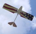
I think if there is zero binding with the measurements as you describe, you have fixed your problem.


Of course, you need to bear in mind where I am coming from. What I am working on putting back together doesn't have anything level in it's cage either...


As Dear Old Dad used to say, "A man on a horse at thirty yards probably won't notice it."


Richard Pike

MKIII N420P (420ldPoops)
| | - The Matronics Kolb-List Email Forum - | | | Use the List Feature Navigator to browse the many List utilities available such as the Email Subscriptions page, Archive Search & Download, 7-Day Browse, Chat, FAQ, Photoshare, and much more:
http://www.matronics.com/Navigator?Kolb-List |
|
| Description: |
|
| Filesize: |
172.54 KB |
| Viewed: |
15404 Time(s) |

|
|
|
| Back to top |
|
|
capedavis(at)yahoo.com
Guest
|
| Posted: Mon Aug 09, 2010 8:21 am Post subject: Acceptable horizontal stabilizer adjustment |
|
|
Chris , I think you have  your aircraft well within acceptable limits for the

speeds at which we fly , the 1.5 inch difference in your cables was most likely

the most out of whack measurement that you had and you fixed that ! With your

measurements within 1/8 inch and considering the fact that I never  had my tail

wires so tight that I couldn't move my horizontal stabilizer 1/8 inch up and

down I think you should be all right . just my 2 cents. Chris

 Chris Davis

KXP 503 492 hrs

Glider Pilot

Disabled from crash building Firefly


---
| | - The Matronics Kolb-List Email Forum - | | | Use the List Feature Navigator to browse the many List utilities available such as the Email Subscriptions page, Archive Search & Download, 7-Day Browse, Chat, FAQ, Photoshare, and much more:
http://www.matronics.com/Navigator?Kolb-List |
|
|
|
| Back to top |
|
|
Chris_A
Joined: 20 Jun 2010
Posts: 20
Location: Mustang OK
|
| Posted: Mon Aug 09, 2010 8:38 am Post subject: Re: Acceptable horizontal stabilizer adjustment |
|
|
Richard,

Is that your Kolb? That's the one that hit the fence and went nose over correct? I think it's going to need a new tail boom!


I think I will stop worrying about a .5" and go flying.


Thanks for every ones input.


Chris
| | - The Matronics Kolb-List Email Forum - | | | Use the List Feature Navigator to browse the many List utilities available such as the Email Subscriptions page, Archive Search & Download, 7-Day Browse, Chat, FAQ, Photoshare, and much more:
http://www.matronics.com/Navigator?Kolb-List |
|
|
|
| Back to top |
|
|
mdnanwelch7(at)hotmail.co
Guest
|
| Posted: Mon Aug 09, 2010 8:59 am Post subject: Acceptable horizontal stabilizer adjustment |
|
|
Chris,
Did you say Lexan" template?? Ah HAH!! You were listening!!!
Regarding your comment about how to check of the underside vertical stabilizer mount being EXACTLY
180 degrees from the top, try this;
Get a long piece of construction paper (approx 24"), cut it to be about 1-2" wide. Wrap the boomtube
very snugley with the paper strip, where they run past each other, not overlapping each other. Make a
mark with a pen on BOTH pieces anywhere where they are side by side. Remove the long strip of paper.
Those two marks are exactly the boomtube's circumference. Cut off excess paper strip at 90 deg angle
at each pen mark.
Next, you need to find the paper's midpoint, so fold it to create a crease which will be exactly 1/2 of the boomtube's
circumference, and make another pen mark at this midpoint crease.
Lastly, put your paper back on the boomtube, centering the ends at the top mount, with the cut ends butted together,
and tape the strip securely!! If you look underneath, at your midpoint mark, you will see EXACTLY where 180
degrees of your top mark is.
Regarding you empennage situation; were you saying "it's close enough, now"?
Mike Welch
> Hi Guys,
| Quote: |
Thanks for all the in put with my issue. I spent yesterday with a tape measure and a level and I came to several realizations.
One: Although this firestar is extremely well built, I can't find a level spot on the thing including the factory welded cage. No amount of shimming would produce a level reading at any two points. I hung the plane by the CG off the rafters in the shop and shimmed the tires with blocks, then shimmed the tail stand. No luck.
Two: The plane leans counter clockwise .5" resting on level ground with the tires at any and equal pressure. I measured off the either side of the cage, being it was welded in a jig and should therefore be square. (see#1) This was confirmed with both a tape measure and by the angled wear on the tail wheel. I can not see any bend in the gear and they are exactly the same length. I did the repair with the plane suspended and leveled it with a plumb bob off the prop shaft. So in the air the top center line of the tube is properly located off the shaft.
Three: After the tail boom was assembled I set the plane back on the ground and it resumed it's .5" counter clockwise list. At the time I didn't realize this.
Four: I still managed to get the tail ring off center. After I made an absolutely level/flat spot I measured from the ground to the bottom of the horizontal control horn at each end just before the welds. (With the plane as level as I could get it with the plumb bob off shaft) There is a .125" difference end to end. I am however positive that the top forward bracket for the vertical is absolutely, dead nuts centered on the tube. I believe I got the bottom one off less than 1/8 but I can't find a good way to measure it. I must have canted the ring, thinking the front brackets were enough to keep it centered.
Five: I never pulled the tail brace wires off the horizontals, nor did I tighten/loosen the turn buckles(safety wired). After I really got looking at them I noticed the top two where different lengths. 1.5" to be exact. Well I switched them around and now the horizontals are within .250 of each other so I cut the safety wire and adjusted them until both side were equal. I still have a lot of play left in both turn buckles. I have come to the conclusion that the tail was never really square and I had no reason to notice it.
I know I centered all the holes as well as anyone could. Using the lexan template I hit every single hole in the H-brace dead on. I think I had several factors working against me. The biggest was thinking the front brackets were enough to center the ring.
So with the brace wires switched and the plane raised .5" clockwise everything is and looks square except for the horizontal control horn. There is no binding in any of the controls what so ever. I am still considering pulling the rivets but I really think what I have now is closer than it was before and it flew great then.
What do you guys think?
Thanks
Chris
Read this topic online here:
http://forums.matronics.com/viewtopic.php?p=308054#308054
Archive Search & Download, 7-Day Browse, Chat, FAQ,
|
>==
[quote]
| | - The Matronics Kolb-List Email Forum - | | | Use the List Feature Navigator to browse the many List utilities available such as the Email Subscriptions page, Archive Search & Download, 7-Day Browse, Chat, FAQ, Photoshare, and much more:
http://www.matronics.com/Navigator?Kolb-List |
|
|
|
| Back to top |
|
|
williamtsullivan(at)att.n
Guest
|
| Posted: Mon Aug 09, 2010 10:55 am Post subject: Acceptable horizontal stabilizer adjustment |
|
|
--- On Mon, 8/9/10, Chris_A <50calibercruiser(at)cox.net> wrote:


So with the brace wires switched and the plane raised .5" clockwise everything is and looks square except for the horizontal control horn. There is no binding in any of the controls what so ever. I am still considering pulling the rivets but I really think what I have now is closer than it was before and it flew great then.


What do you guys think?


Thanks

   Chris


   Chris- One of the guys once did some video of his tail in flight, and you wouldn't believe how much it twists and thrashes around.  Much more than an inch or so.  Just put it together, and fly.

   On my rebuild of the Firestar, I noticed that the original cage wasn't absolutely precise.  When I re-did the cage, it's probably well within factory tolerance.  I once had occassion to measure about 30 IHC truck tractors, in order to rebuild a badly wrecked truck.  Every measurement was different, sometimes as much as 1 1/2" side to side- locating the rear axles!  As long as everything is solid, and reasonably square, don't worry about it.

   If someone can reference you to those twisting tail videos, I think you will feel much better.


                                                Bill Sullivan

                                                Windsor Locks, Ct.

                                                FS 447

  --> http://www.matronics.com/con=================


 [quote][b]
| | - The Matronics Kolb-List Email Forum - | | | Use the List Feature Navigator to browse the many List utilities available such as the Email Subscriptions page, Archive Search & Download, 7-Day Browse, Chat, FAQ, Photoshare, and much more:
http://www.matronics.com/Navigator?Kolb-List |
|
|
|
| Back to top |
|
|
John Hauck

Joined: 09 Jan 2006
Posts: 4639
Location: Titus, Alabama (hauck's holler)
|
| Posted: Mon Aug 09, 2010 11:30 am Post subject: Acceptable horizontal stabilizer adjustment |
|
|
If someone can reference you to those twisting        tail videos, I think you will feel much better.


                                                             Bill Sullivan

                                                             Windsor Locks, Ct.

                                                             FS 447


       Bill S/Folks:


       Most Kolbs I take a look at fly with the tail wires too        loose.  Most of the tail shake and movement you talk about is caused        by improperly tensioned tail wires.


       I snug mine up until they twang, not thump.  I        don't get all that tail dance in the air.


       john h

       mkIII


[quote]

 [b]
| | - The Matronics Kolb-List Email Forum - | | | Use the List Feature Navigator to browse the many List utilities available such as the Email Subscriptions page, Archive Search & Download, 7-Day Browse, Chat, FAQ, Photoshare, and much more:
http://www.matronics.com/Navigator?Kolb-List |
|
_________________
John Hauck
MKIII/912ULS
hauck's holler
Titus, Alabama |
|
| Back to top |
|
|
williamtsullivan(at)att.n
Guest
|
| Posted: Mon Aug 09, 2010 12:39 pm Post subject: Acceptable horizontal stabilizer adjustment |
|
|
John- I think it might have been Larry Cottrel that did the video.  It does show an amazing amount of tail twisting, and I think it's the boom.  Or, it might be some kind of illusion.  It is a very impressive piece of footage.


                                                   Bill Sullivan

                                                   Windsor Locks, Ct.

                                                   FS 447

 [quote][b]
| | - The Matronics Kolb-List Email Forum - | | | Use the List Feature Navigator to browse the many List utilities available such as the Email Subscriptions page, Archive Search & Download, 7-Day Browse, Chat, FAQ, Photoshare, and much more:
http://www.matronics.com/Navigator?Kolb-List |
|
|
|
| Back to top |
|
|
|
|
You cannot post new topics in this forum
You cannot reply to topics in this forum
You cannot edit your posts in this forum
You cannot delete your posts in this forum
You cannot vote in polls in this forum
You cannot attach files in this forum
You can download files in this forum
|
Powered by phpBB © 2001, 2005 phpBB Group
|

