 |
Matronics Email Lists
Web Forum Interface to the Matronics Email Lists
|
| View previous topic :: View next topic |
| Author |
Message |
jonlaury
Joined: 06 Nov 2006
Posts: 336
|
 Posted: Tue Sep 21, 2010 7:50 am Post subject: Potentiometer , 3 lugs Posted: Tue Sep 21, 2010 7:50 am Post subject: Potentiometer , 3 lugs |
 |
|
There are 3 solder lugs on a sliding trim pot that I'm using to drive my AFS flap position indicator. Pins 1 & 2, through my multi-meter, indicate a 0-5K ohm range, so I assume those are the power and ground pins.


What does pin 3 do? That must drive the indicator right? How do I check it with the m-m?


Thanks,

J
| | - The Matronics AeroElectric-List Email Forum - | | | Use the List Feature Navigator to browse the many List utilities available such as the Email Subscriptions page, Archive Search & Download, 7-Day Browse, Chat, FAQ, Photoshare, and much more:
http://www.matronics.com/Navigator?AeroElectric-List |
|
|
|
| Back to top |
|
 |
user9253
Joined: 28 Mar 2008
Posts: 1927
Location: Riley TWP Michigan
|
 Posted: Wed Sep 22, 2010 1:39 am Post subject: Re: Potentiometer , 3 lugs Posted: Wed Sep 22, 2010 1:39 am Post subject: Re: Potentiometer , 3 lugs |
 |
|
jonlaury,


Depending on how the pot is made, chances are that the two outside terminals are the ones that the supply voltage is applied to.  When checked with an ohm meter, the resistance (5KΩ) of these two terminals should not change as the slider is moved.


The resistance of the center terminal varies with the slider as measured to either of the other two terminals.  This terminal that varies (probably #2) is the signal terminal that will indicate the flap position.

Joe
| | - The Matronics AeroElectric-List Email Forum - | | | Use the List Feature Navigator to browse the many List utilities available such as the Email Subscriptions page, Archive Search & Download, 7-Day Browse, Chat, FAQ, Photoshare, and much more:
http://www.matronics.com/Navigator?AeroElectric-List |
|
_________________
Joe Gores |
|
| Back to top |
|
 |
jonlaury
Joined: 06 Nov 2006
Posts: 336
|
 Posted: Thu Sep 23, 2010 9:09 am Post subject: Re: Potentiometer , 3 lugs Posted: Thu Sep 23, 2010 9:09 am Post subject: Re: Potentiometer , 3 lugs |
 |
|
Thanks Joe,

My slide pot has pins 1,2,3 at one end and 1,2 at the other. I got joy when I connected pins 1 at one end and 2 at the other. The 5K range was displayed on my meter when I moved the slider. I assumed 1&2 to be the pos/neg pins. Assuming that pin 3 was the signal pin, I put the meter between 1& 3 and got nothing and my brain hit the wall because of my assumption that 1&2 were the pos/neg pins..


John
| | - The Matronics AeroElectric-List Email Forum - | | | Use the List Feature Navigator to browse the many List utilities available such as the Email Subscriptions page, Archive Search & Download, 7-Day Browse, Chat, FAQ, Photoshare, and much more:
http://www.matronics.com/Navigator?AeroElectric-List |
|
|
|
| Back to top |
|
 |
nuckolls.bob(at)aeroelect
Guest
|
 Posted: Thu Sep 23, 2010 10:40 am Post subject: Potentiometer , 3 lugs Posted: Thu Sep 23, 2010 10:40 am Post subject: Potentiometer , 3 lugs |
 |
|
At 12:09 PM 9/23/2010, you wrote:

 --> AeroElectric-List message posted by: "jonlaury" <jonlaury(at)impulse.net>


 Thanks Joe,

 My slide pot has pins 1,2,3 at one end and 1,2 at the other. I got joy when I connected pins 1 at one end and 2 at the other. The 5K range was displayed on my meter when I moved the slider. I assumed 1&2 to be the pos/neg pins. Assuming that pin 3 was the signal pin, I put the meter between 1& 3 and got nothing and my brain hit the wall because of my assumption that 1&2 were the pos/neg pins..


    Pin numbers or other markings not withstanding, the

    functionality of slide pots yields readily to

    inspection.


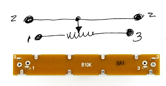
     For example, in this device:


 [img]cid:.0[/img]


    . . . I would have guessed that "2" and "2" on each end

    are connected internally to each end of the wiper's

    slip-track. 1 and 3 would be the ends of the pot's resistance

    element.  I suspect that an ohmmeter inspection of your device

    will show that all pins of like number are connected to each

    other. The cluster of 1,2,3 at one end is conducive to hooking

    the pot up with a twisted trio or some such.  So it's

    probably unimportant which "1" or "3" you connect to, functionality

    will not be affected.  Either 1 or 3 can be (+) or (-) and

    that will be determined by whether or not the indicator reads

    in the right direction. Installation instructions for use

    of this pot SHOULD be explicit in this regard. But if not,

    then be prepared to reverse 1 and 3 connections if the

    operation is 'backwards'.


   Bob . . .
| | - The Matronics AeroElectric-List Email Forum - | | | Use the List Feature Navigator to browse the many List utilities available such as the Email Subscriptions page, Archive Search & Download, 7-Day Browse, Chat, FAQ, Photoshare, and much more:
http://www.matronics.com/Navigator?AeroElectric-List |
|
| Description: |
|
| Filesize: |
58.09 KB |
| Viewed: |
3637 Time(s) |

|
|
|
| Back to top |
|
 |
|
|
You cannot post new topics in this forum
You cannot reply to topics in this forum
You cannot edit your posts in this forum
You cannot delete your posts in this forum
You cannot vote in polls in this forum
You cannot attach files in this forum
You can download files in this forum
|
Powered by phpBB © 2001, 2005 phpBB Group
|


