 |
Matronics Email Lists
Web Forum Interface to the Matronics Email Lists
|
| View previous topic :: View next topic |
| Author |
Message |
BobbyPaulk(at)comcast.net
Guest
|
 Posted: Sun Oct 31, 2010 11:06 am Post subject: Amp Meter Posted: Sun Oct 31, 2010 11:06 am Post subject: Amp Meter |
 |
|
List,

While we are on the subject. I have a digital Amp Meter in the Dynon DEK 180. The output of the Alt. from the Jab. 3300 varies wildly from a minus to plus 15 or 20. It never settles down to a steady rate either with a heavy load, marginal load or no load. I am using the Kubota regulator ( I think ). Can anyone tell me if this problem can be rectified : ) pun intended.


Bobby

Jacksonville, Fl.


 [quote][b]
| | - The Matronics JabiruEngine-List Email Forum - | | | Use the List Feature Navigator to browse the many List utilities available such as the Email Subscriptions page, Archive Search & Download, 7-Day Browse, Chat, FAQ, Photoshare, and much more:
http://www.matronics.com/Navigator?JabiruEngine-List |
|
|
|
| Back to top |
|
 |
mhubel
Joined: 05 Sep 2009
Posts: 141
|
| Posted: Sun Oct 31, 2010 11:49 am Post subject: Amp Meter |
|
|
Bobby,
   I have exactly the same combination. I believe what you are seeing is the combination of the slightly quarky current reading system in the Dynon combined with the less than smooth regulation mode of the regulator.
   That said, my system varies on the order of +/- 5 amps most of the time with occasional peaks that are greater.
   I assume you have verified that there are no bad connections anywhere in the electrical system.
   If the voltage is being held at a fairly constant (I would say 14.0-14.5V) at over 2000 RPM, I would not worry too much. Still these swings are a bit higher than I see.
   The regulator depends on the sampling lead having a noise free connection to the battery. The wiring from the sampling lead (I believe it was pin 5 on the connector) needs have a very low resistance path to the battery.
   The other thing is that this type of regulator also assumes that the battery is well behaved - as in good condition. As the battery ages, you will probably get larger voltage/current swings than with a conventional field current type regulator.
On 10/31/2010 3:03 PM, BobbyPaulk(at)comcast.net (BobbyPaulk(at)comcast.net) wrote: | Quote: | p { margin: 0; } List,
While we are on the subject. I have a digital Amp Meter in the Dynon DEK 180. The output of the Alt. from the Jab. 3300 varies wildly from a minus to plus 15 or 20. It never settles down to a steady rate either with a heavy load, marginal load or no load. I am using the Kubota regulator ( I think ). Can anyone tell me if this problem can be rectified : ) pun intended.
Bobby
Jacksonville, Fl.
--
Mark Hubelbank
NorthEast Monitoring
2 Clock Tower Place
Suite 555
Maynard, MA, 01754 - USA
mhubel(at)nemon.com (mhubel(at)nemon.com)
978-443-3955 |
| | - The Matronics JabiruEngine-List Email Forum - | | | Use the List Feature Navigator to browse the many List utilities available such as the Email Subscriptions page, Archive Search & Download, 7-Day Browse, Chat, FAQ, Photoshare, and much more:
http://www.matronics.com/Navigator?JabiruEngine-List |
|
_________________
Mark Hubelbank
N708HU
CH601XL
Jabiru 3300
Rotec TBI 40-3 carb
Sensenich ground adj prop.
240 hr TAF
Pictures at photo.hubbles.com |
|
| Back to top |
|
|
matronics(at)rtist.nl
Guest
|
| Posted: Sun Oct 31, 2010 12:01 pm Post subject: Amp Meter |
|
|
Bobby,
Where in the circuit do you have the shunt wired in? It should be somewhere on the DC side of the regulator. If you have the shunt on the AC side (in series with one of the pale blue wires) then that would explain your observation.
Rob
On 10/31/2010 8:03 PM, BobbyPaulk(at)comcast.net (BobbyPaulk(at)comcast.net) wrote: [quote] p { margin: 0; } List,
While we are on the subject. I have a digital Amp Meter in the Dynon DEK 180. The output of the Alt. from the Jab. 3300 varies wildly from a minus to plus 15 or 20. It never settles down to a steady rate either with a heavy load, marginal load or no load. I am using the Kubota regulator ( I think ). Can anyone tell me if this problem can be rectified : ) pun intended.
Bobby
Jacksonville, Fl.
[b]
| | - The Matronics JabiruEngine-List Email Forum - | | | Use the List Feature Navigator to browse the many List utilities available such as the Email Subscriptions page, Archive Search & Download, 7-Day Browse, Chat, FAQ, Photoshare, and much more:
http://www.matronics.com/Navigator?JabiruEngine-List |
|
|
|
| Back to top |
|
|
Garth
Joined: 18 Feb 2010
Posts: 5
|
| Posted: Sun Oct 31, 2010 12:57 pm Post subject: Amp Meter |
|
|
Bobby, et al,
I have the same issue and about the same swings with my Dynon 180 and Jab 3300. I would get high and low alarms, almost no matter where I set them ... very annoying, especially to a passenger. All connections were checked and secure. I concluded the readings were effectively useless. There has been some discussion on this on the Dynon Forum as others (but not everyone) are having this issue as well. One possible conclusion was that the issue has something to do with how the Dynon processes the small mv readings across the shunt. As what is hopefully a temporary measure until a fix is found or available, I installed an inexpensive automotive type analog ammeter gauge and disabled the alarms in the D180. The readings with the new meter are very steady and predictable, ie slightly negative at idle/low rpm and then slightly positive as rpms are increased, until the battery is fully recharged and then it reads very close to zero. Yet the Dynon readings are bouncing wildly.
FYI
Garth
From: Mark Hubelbank <mhubel(at)nemon.com>
To: jabiruengine-list(at)matronics.com
Sent: Sun, October 31, 2010 3:46:36 PM
Subject: Re: Amp Meter
Bobby,
I have exactly the same combination. I believe what you are seeing is the combination of the slightly quarky current reading system in the Dynon combined with the less than smooth regulation mode of the regulator.
That said, my system varies on the order of +/- 5 amps most of the time with occasional peaks that are greater.
I assume you have verified that there are no bad connections anywhere in the electrical system.
If the voltage is being held at a fairly constant (I would say 14.0-14.5V) at over 2000 RPM, I would not worry too much. Still these swings are a bit higher than I see.
The regulator depends on the sampling lead having a noise free connection to the battery. The wiring from the sampling lead (I believe it was pin 5 on the connector) needs have a very low resistance path to the battery.
The other thing is that this type of regulator also assumes that the battery is well behaved - as in good condition. As the battery ages, you will probably get larger voltage/current swings than with a conventional field current type regulator.
On 10/31/2010 3:03 PM, BobbyPaulk(at)comcast.net (BobbyPaulk(at)comcast.net) wrote: [quote] p {margin:0;} List,
While we are on the subject. I have a digital Amp Meter in the Dynon DEK 180. The output of the Alt. from the Jab. 3300 varies wildly from a minus to plus 15 or 20. It never settles down to a steady rate either with a heavy load, marginal load or no load. I am using the Kubota regulator ( I think ). Can anyone tell me if this problem can be rectified : ) pun intended.
Bobby
Jacksonville, Fl.
-- Mark Hubelbank NorthEast Monitoring 2 Clock Tower Place Suite 555 Maynard, MA, 01754 - USA mhubel(at)nemon.com (mhubel(at)nemon.com) 978-443-3955[b]
| | - The Matronics JabiruEngine-List Email Forum - | | | Use the List Feature Navigator to browse the many List utilities available such as the Email Subscriptions page, Archive Search & Download, 7-Day Browse, Chat, FAQ, Photoshare, and much more:
http://www.matronics.com/Navigator?JabiruEngine-List |
|
|
|
| Back to top |
|
|
DaveG601XL
Joined: 27 Oct 2006
Posts: 351
Location: Cincinnati, Oh
|
| Posted: Mon Nov 01, 2010 3:06 am Post subject: Re: Amp Meter |
|
|
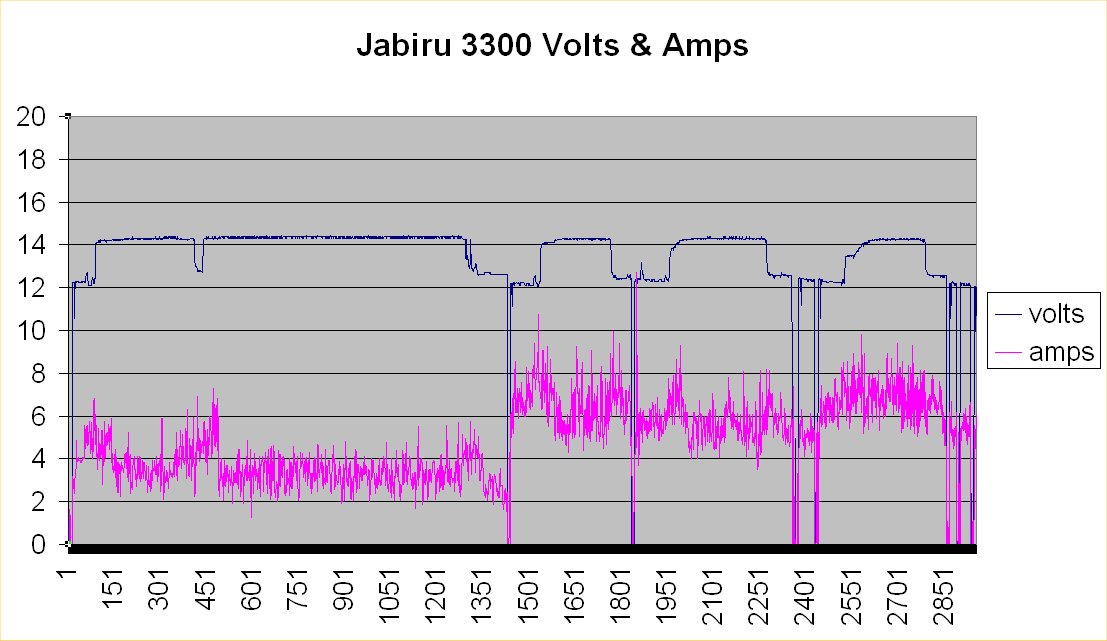
My Jabiru/Dynon D180 shunt is on the primary feed wire right before the main bus.  This makes it is a load meter with a 0-20 amp type reading.  Looking at the attached plot in the short term (point-to-point), shows about a +/- 2 amp variation or noise in amperage.  I don't know what other aircraft ammeter plots look like, but I consider this an acceptable amount of variation for my aircraft.  As has already been asked, where in the electrical circuit is your shunt?  I assume it is in one of the three locations suggested in the Dynon install manual.


Good luck,
| | - The Matronics JabiruEngine-List Email Forum - | | | Use the List Feature Navigator to browse the many List utilities available such as the Email Subscriptions page, Archive Search & Download, 7-Day Browse, Chat, FAQ, Photoshare, and much more:
http://www.matronics.com/Navigator?JabiruEngine-List |
|
| Description: |
|
| Filesize: |
107.12 KB |
| Viewed: |
6385 Time(s) |
|
_________________
David Gallagher
Cincinnati, OH area |
|
| Back to top |
|
|
flyadive(at)gmail.com
Guest
|
| Posted: Mon Nov 01, 2010 4:55 am Post subject: Amp Meter |
|
|
David:


Your terminology is a bit askew.

A LOAD meter is a device that calculates the Voltage and the Amperage and gives a Wattage.  YET!  I have seen the wattage terminology left off and Amps substituted.


Putting an ammeter in series with the battery will show the amperage/current flowing to or from the the battery.  Your 0 - 20 Amp meter will show ONLY current going to the Buss.  You require two conditions to show + & - current:

 1 - A meter with the capability of displaying + & - current (Zero Center Meter - Analog or a Digital - Circuit to do the sensing) and

2 - The output from the alternator to be BEFORE the Amp Meter.

 That way it will show current going TO the Battery - Charge State.  Or FROM the Battery - Discharge State.

I missed the "plot" you are referring to ... Did you or someone graph a charge - discharge condition?  What is this "noise" you are referring to, is that your terminology?  I have never heard of amperage referred to as noise? Voltage, YES!

 But, I get the feeling that you are referring to the Idle State of your electrical system.  What it requires without any additional components turned on.  Just the state of Master Contactor closed & Alternator charging, am I close?


Barry

On Mon, Nov 1, 2010 at 7:06 AM, DaveG601XL <david.m.gallagher(at)ge.com (david.m.gallagher(at)ge.com)> wrote:

 [quote]--> JabiruEngine-List message posted by: "DaveG601XL" <david.m.gallagher(at)ge.com (david.m.gallagher(at)ge.com)>


 My Jabiru/Dynon D180 shunt is on the primary feed wire right before the main bus.  This makes it is a load meter with a 0-20 amp type reading.  Looking at the attached plot in the short term (point-to-point), shows about a +/- 2 amp variation or noise in amperage.  I don't know what other aircraft ammeter plots look like, but I consider this an acceptable amount of variation for my aircraft.  As has already been asked, where in the electrical circuit is your shunt?  I assume it is in one of the three locations suggested in the Dynon install manual.


 Good luck,


 --------

 David Gallagher

 601 XL/Jabiru 3300

 First flight 7/24/08

 Upgraded 3/19/10

 150+ hours and climbing!


[b]
| | - The Matronics JabiruEngine-List Email Forum - | | | Use the List Feature Navigator to browse the many List utilities available such as the Email Subscriptions page, Archive Search & Download, 7-Day Browse, Chat, FAQ, Photoshare, and much more:
http://www.matronics.com/Navigator?JabiruEngine-List |
|
|
|
| Back to top |
|
|
DaveG601XL
Joined: 27 Oct 2006
Posts: 351
Location: Cincinnati, Oh
|
| Posted: Mon Nov 01, 2010 8:35 am Post subject: Re: Amp Meter |
|
|
Barry,


Not being an electrical expert, I can only aspire to try and correctly interpret terminology from those who are.  An example being from Bob Nuckolls Aeroelectric Digest "Loadmeters only read 0 to some value either in amps full scale (or in the case of the ones I sell, 0-100% of alternator output)."  That is about as deep as I can describe a loadmeter.


Terminology aside, my configuration of metering the load is that I only show the + amperage going to my aircraft loads. As opposed to two other shunt locations that would show (1) +- flow in and out of the battery or (2) + only, but going to both aircraft loads and the battery.
| | - The Matronics JabiruEngine-List Email Forum - | | | Use the List Feature Navigator to browse the many List utilities available such as the Email Subscriptions page, Archive Search & Download, 7-Day Browse, Chat, FAQ, Photoshare, and much more:
http://www.matronics.com/Navigator?JabiruEngine-List |
|
_________________
David Gallagher
Cincinnati, OH area |
|
| Back to top |
|
|
flyadive(at)gmail.com
Guest
|
| Posted: Mon Nov 01, 2010 9:42 am Post subject: Amp Meter |
|
|
Hi David;
You do not require two shunts. Only one shunt and a meter capable of reading both Positive and Negative current flow.
If I may, let me describe what a SHUNT is and why it is required.
A SHUNT is exactly what the word says it is... "A way around", "To circumvent" as in a Shun-pike - A way around a pike.
Why are there shunts? It is not practicable to manufacture an AMMETER for ever current range required by different applications. So, there are some basic Ammeters at basic current levels: 100 uA. 1 mA, 100 mA & 1 A.
The SHUNT is placed in PARALLEL with the above ammeter(s) to divert the HIGH current around the Meter, while allowing the small amount through the meter.
For example:-
If you wanted to read 10 Amps you may use a 1 Amp Meter with a SHUNT capable of carrying 9 Amps.
The meter reads 0 to 1 and that would be 0 to 10 Amps with the shunt installed.
How is the value of the shunt determined?
By RESISTANCE.
If the Meter has an internal resistance of say 100 Ohms the Shunt must carry a ratio of (X):
1 Amp is to 10 Amps
as
100 Ohms is to X Ohms
X being 0.1
Or 0.1 Ohms
The direction of the current does not mater, NOT to the shunt... Only to the Meter.
On Mon, Nov 1, 2010 at 12:35 PM, DaveG601XL <david.m.gallagher(at)ge.com (david.m.gallagher(at)ge.com)> wrote:
| Quote: | --> JabiruEngine-List message posted by: "DaveG601XL" <david.m.gallagher(at)ge.com (david.m.gallagher(at)ge.com)>
Barry,
Not being an electrical expert, I can only aspire to try and correctly interpret terminology from those who are. An example being from Bob Nuckolls Aeroelectric Digest "Loadmeters only read 0 to some value either in amps full scale (or in the case of the ones I sell, 0-100% of alternator output)." That is about as deep as I can describe a loadmeter.
Terminology aside, my configuration of metering the load is that I only show the + amperage going to my aircraft loads. As opposed to two other shunt locations that would show (1) +- flow in and out of the battery or (2) + only, but going to both aircraft loads and the battery.
--------
David Gallagher
601 XL/Jabiru 3300
First flight 7/24/08
Upgraded 3/19/10
160+ hours and climbing!
Read this topic online here:
http://forums.matronics.com/viewtopic.php?p=317763#317763
===========
="_blank">www.aeroelectric.com
ooks.com" target="_blank">www.buildersbooks.com
et="_blank">www.homebuilthelp.com
="_blank">http://www.matronics.com/contribution
le, List Admin.
===========
-List" target="_blank">http://www.matronics.com/Navigator?JabiruEngine-List
===========
http://forums.matronics.com
===========
|
--
Barry
"Chop'd Liver"
[quote][b]
| | - The Matronics JabiruEngine-List Email Forum - | | | Use the List Feature Navigator to browse the many List utilities available such as the Email Subscriptions page, Archive Search & Download, 7-Day Browse, Chat, FAQ, Photoshare, and much more:
http://www.matronics.com/Navigator?JabiruEngine-List |
|
|
|
| Back to top |
|
|
flyadive(at)gmail.com
Guest
|
| Posted: Mon Nov 01, 2010 10:25 am Post subject: Amp Meter |
|
|
Whoops... Sorry Gaggle - The email got away from me. Before I was finished.
I'll finish up and resend it.
Barry
On Mon, Nov 1, 2010 at 1:39 PM, FLYaDIVE <flyadive(at)gmail.com (flyadive(at)gmail.com)> wrote:
| Quote: | Hi David;
You do not require two shunts. Only one shunt and a meter capable of reading both Positive and Negative current flow.
If I may, let me describe what a SHUNT is and why it is required.
A SHUNT is exactly what the word says it is... "A way around", "To circumvent" as in a Shun-pike - A way around a pike.
Why are there shunts? It is not practicable to manufacture an AMMETER for ever current range required by different applications. So, there are some basic Ammeters at basic current levels: 100 uA. 1 mA, 100 mA & 1 A.
The SHUNT is placed in PARALLEL with the above ammeter(s) to divert the HIGH current around the Meter, while allowing the small amount through the meter.
For example:-
If you wanted to read 10 Amps you may use a 1 Amp Meter with a SHUNT capable of carrying 9 Amps.
The meter reads 0 to 1 and that would be 0 to 10 Amps with the shunt installed.
How is the value of the shunt determined?
By RESISTANCE.
If the Meter has an internal resistance of say 100 Ohms the Shunt must carry a ratio of (X):
1 Amp is to 10 Amps
as
100 Ohms is to X Ohms
X being 0.1
Or 0.1 Ohms
The direction of the current does not mater, NOT to the shunt... Only to the Meter.
On Mon, Nov 1, 2010 at 12:35 PM, DaveG601XL <david.m.gallagher(at)ge.com (david.m.gallagher(at)ge.com)> wrote:
| Quote: | --> JabiruEngine-List message posted by: "DaveG601XL" <david.m.gallagher(at)ge.com (david.m.gallagher(at)ge.com)>
Barry,
Not being an electrical expert, I can only aspire to try and correctly interpret terminology from those who are. An example being from Bob Nuckolls Aeroelectric Digest "Loadmeters only read 0 to some value either in amps full scale (or in the case of the ones I sell, 0-100% of alternator output)." That is about as deep as I can describe a loadmeter.
Terminology aside, my configuration of metering the load is that I only show the + amperage going to my aircraft loads. As opposed to two other shunt locations that would show (1) +- flow in and out of the battery or (2) + only, but going to both aircraft loads and the battery.
--------
David Gallagher
601 XL/Jabiru 3300
First flight 7/24/08
Upgraded 3/19/10
160+ hours and climbing!
Read this topic online here:
http://forums.matronics.com/viewtopic.php?p=317763#317763
===========
="_blank">www.aeroelectric.com
ooks.com" target="_blank">www.buildersbooks.com
et="_blank">www.homebuilthelp.com
="_blank">http://www.matronics.com/contribution
le, List Admin.
===========
-List" target="_blank">http://www.matronics.com/Navigator?JabiruEngine-List
===========
http://forums.matronics.com
===========
|
--
Barry
"Chop'd Liver"
|
--
Barry
"Chop'd Liver"
[quote][b]
| | - The Matronics JabiruEngine-List Email Forum - | | | Use the List Feature Navigator to browse the many List utilities available such as the Email Subscriptions page, Archive Search & Download, 7-Day Browse, Chat, FAQ, Photoshare, and much more:
http://www.matronics.com/Navigator?JabiruEngine-List |
|
|
|
| Back to top |
|
|
|
|
You cannot post new topics in this forum
You cannot reply to topics in this forum
You cannot edit your posts in this forum
You cannot delete your posts in this forum
You cannot vote in polls in this forum
You cannot attach files in this forum
You can download files in this forum
|
Powered by phpBB © 2001, 2005 phpBB Group
|

