 |
Matronics Email Lists
Web Forum Interface to the Matronics Email Lists
|
| View previous topic :: View next topic |
| Author |
Message |
byoungplumbing(at)gmail.c
Guest
|
 Posted: Fri Feb 18, 2011 9:25 pm Post subject: toe in Posted: Fri Feb 18, 2011 9:25 pm Post subject: toe in |
 |
|
kolbers,,
this is how I calculated the angles for toe in on my mkiii
initial figures were done by hanging a pipe under the fuselage on the centerline, then hanging a 5 ft pipe along the outside of the wheel, then measuring from each side to center,, I think this was prone to more error as the pipe along the wheels could vary in angle by whether the pipe was on the sidewall or on a raised letter.
subsequent measurements were made after picking the brain of an a&p
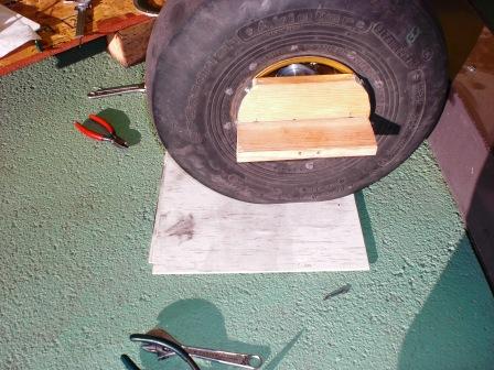
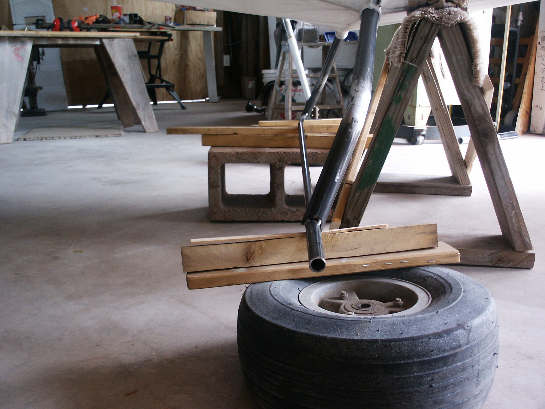
I made a piece of wood cut to the diameter of the wheel , and placing a piece of sheet metal to keep it centered on the rim. then added a side piece to help hold a carpenter square. then placed the wheel on a grease plate, (2 pieces of floor tile with a layer of grease between them. could use alum sheets)
[img]cid:3E442DAB8E3A4103A3F8F22FF71A7760(at)laptop1[/img]
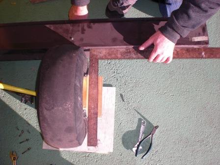
by putting a straight board, or I used a steel angle supported with sections of 2x8 to hold it at the correct height. and held against the back of both tires. then used a carpenters square to hold against the straight angle. and laid it on the wheel bracket.
[img]cid:A3820E7CA0D847C4B96A50399BF2ECD5(at)laptop1[/img]
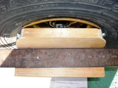
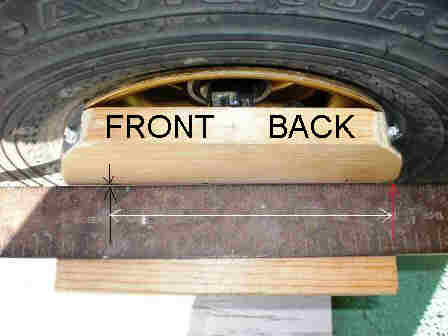
then holding the square against the back of the block measured the distance from the edge of the square to the front of the block. or more specific a spot on the block 5.725 inches from the back edge of the block. this measurement was chosen because of the ratio between the measurement and the angle.
[img]cid:58DC769DD86A4538A073F6536E007D5C(at)laptop1[/img]
if the measurement from the square to the tick mark on the front (left) side of the block was .052 inches the angle is determined by moving the dismal 1 space to the right. or .52 deg (I learned this nice little association with the distance from the square and tick mark at 5.725 inches and angle quite by accident while playing with a spread sheet,) and it will only work while the angles are very small.
the tangent of the angle = the measurement of the opposite side divided by the adjacent side. but we know the opposite and adjacent, we use the inverse tangent function. the inverse tangent function = the ratio .052/5.725 or TAN-1 power is .52 deg Toe In.
I measured the distance using a caliper depth indicator, on the back of the block it measured 1.5 inches, or the width of the square, and the left side measured at the tick mark 1.552 for the difference of .052 inch.
to measure the camber, place the wood block vertical, and hold the square on the floor and against the block going vertical.
boyd young mkiii
utah
| | - The Matronics Kolb-List Email Forum - | | | Use the List Feature Navigator to browse the many List utilities available such as the Email Subscriptions page, Archive Search & Download, 7-Day Browse, Chat, FAQ, Photoshare, and much more:
http://www.matronics.com/Navigator?Kolb-List |
|
| Description: |
|
| Filesize: |
70.31 KB |
| Viewed: |
6010 Time(s) |
|
| Description: |
|
| Filesize: |
65.26 KB |
| Viewed: |
6010 Time(s) |
|
| Description: |
|
| Filesize: |
61.75 KB |
| Viewed: |
6010 Time(s) |
|
|
|
| Back to top |
|
 |
slyck(at)frontiernet.net
Guest
|
| Posted: Sat Feb 19, 2011 5:53 am Post subject: toe in |
|
|
There is an easy way to see toe-in that I think I may have gotten off this list several years ago.
BTW, the steel legs that I bought from TNK to replace the aluminums a couple years back installed with a
mild but visible amount of positive camber. Positive camber wheels, when installed parallel will want to
track wider and need compensating toe-in.
I just guessed at what would do the job.
If you have a concrete floor with enough room, mark a center line from the tail through the cage to a spot at least ten feet forward of the nose.
Chalk line works, then mark the floor with a felt tip.
Now run the chalk line from behind the wheels, touching at the centerline of the tire and just grazing the front to a point ten feet out.
Snap the chalk line at both wheels and measure the half distances for individual toe and compare to the distance at the main wheels.
I think I did something like 1/4" each wheel. It handles the same on either grass or pavement.
BB
On 19, Feb 2011, at 12:18 AM, b young wrote:
| Quote: | kolbers,,
this is how I calculated the angles for toe in on my mkiii
|
| | - The Matronics Kolb-List Email Forum - | | | Use the List Feature Navigator to browse the many List utilities available such as the Email Subscriptions page, Archive Search & Download, 7-Day Browse, Chat, FAQ, Photoshare, and much more:
http://www.matronics.com/Navigator?Kolb-List |
|
|
|
| Back to top |
|
|
Thom Riddle

Joined: 10 Jan 2006
Posts: 1597
Location: Buffalo, NY, USA (9G0)
|
| Posted: Sat Feb 19, 2011 6:21 am Post subject: Re: toe in |
|
|
Boyd,


Thanks for the explanation and photos of how you did the toe-in measurements. If you experiment with the hardened tubular steel gear leg toe-in and and camber, please let us know how it goes.


After bending my Slingshot hardened tubular steel gear legs last summer, I  straightened them by eyeball in my tube bender.   Once mounted on the airplane the left gear has negative camber (eyeball) but appears to be about neutral in toe-in. The right gear appears neutral in camber with some apparent toe-in. This is with full fuel but nobody in the seats. I flew it several times after this mod before winter came.


It now tracks perfectly true during slow taxi on paved runway but darts side-to-side at a faster pace with much higher pressure in the 600-6 tires than you normally carry. There is no tendency whatsoever to vibrate fore-and aft as you described but this could be due to the completely different angle the gear legs come out of the sockets compared to the standard MkIII leg angles. I'm not satisfied with this so I plan to do some more adjusting(bending) when weather warms up and will try your method of checking the toe-in/out angles.


The only thing I see wrong with this measurement method is that it does not reference the centerline of the fuselage, so it is possible to get camber and toe-in on both sides adjusted just the way you want them and yet the fuselage could be going down the runway at an angle. That should not be a big issue though as it won't affect the tracking on the ground, but could look a little peculiar.  To check for this all you have to do is measure the angle between the piece behind the tires and the boom tube. If it is 90 degrees, it is square with the fuselage.


Please keep us posted on further adjustments or handling results.
| | - The Matronics Kolb-List Email Forum - | | | Use the List Feature Navigator to browse the many List utilities available such as the Email Subscriptions page, Archive Search & Download, 7-Day Browse, Chat, FAQ, Photoshare, and much more:
http://www.matronics.com/Navigator?Kolb-List |
|
_________________
Thom Riddle
Buffalo, NY (9G0)
Don't worry about old age... it doesn't last very long.
- Anonymous |
|
| Back to top |
|
|
slyck(at)frontiernet.net
Guest
|
| Posted: Sat Feb 19, 2011 7:26 am Post subject: toe in |
|
|
-second try...........
There is an easy way to see toe-in that I think I may have gotten off this list several years ago.
BTW, the steel legs that I bought from TNK to replace the aluminums a couple years back installed with a
mild but visible amount of positive camber. Positive camber wheels, when installed parallel will want to
track wider and need compensating toe-in.
I just guessed at what would do the job.
If you have a concrete floor with enough room, mark a center line from the tail through the cage to a spot at least ten feet forward of the nose.
Chalk line works, then mark the floor with a felt tip.
Now run the chalk line from behind the wheels, touching at the centerline of the tire and just grazing the front to a point ten feet out.
Snap the chalk line at both wheels and measure the half distances for individual toe and compare to the distance at the main wheels.
I think I did something like 1/4" each wheel. It handles the same on either grass or pavement.
BB
On 19, Feb 2011, at 12:18 AM, b young wrote:
| Quote: | kolbers,,
this is how I calculated the angles for toe in on my mkiii
|
| | - The Matronics Kolb-List Email Forum - | | | Use the List Feature Navigator to browse the many List utilities available such as the Email Subscriptions page, Archive Search & Download, 7-Day Browse, Chat, FAQ, Photoshare, and much more:
http://www.matronics.com/Navigator?Kolb-List |
|
|
|
| Back to top |
|
|
Mike Welch
Joined: 13 Feb 2011
Posts: 272
|
| Posted: Sat Feb 19, 2011 7:26 am Post subject: toe in |
|
|
>There is an easy way to see toe-in that I think I may have gotten off this list several years ago.
>I just guessed at what would do the job.
>BB
Hi Bob,
When setting up my gear legs, I used a nylon string, rather than a chalkline. I set a very heavy weight
on each end, after I found the centerline of the plane with a plumb bob. However, later, I found this
isn't really necessary to have a centerline.
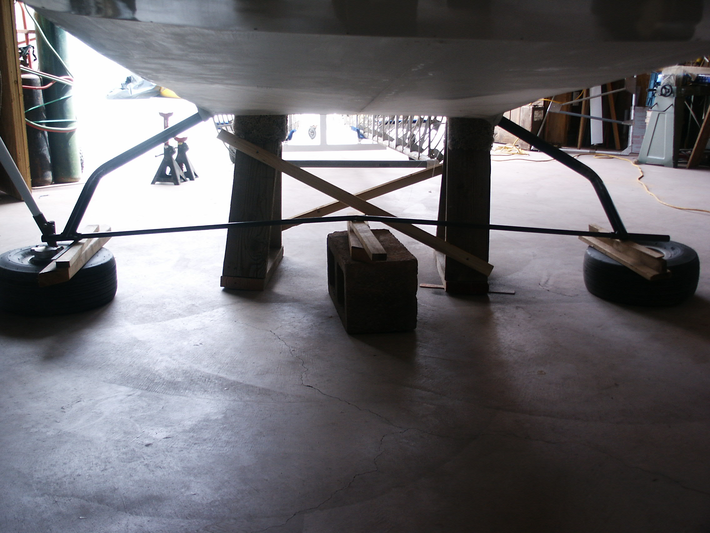
Here's why; If you slide two 5/8"tubes (like chromoly tubing) EXACTLY the same amount, into the axle
sleeves, they will meet at the exact center of the fuselage (assuming the fuselage is square). By eyeballing
between the two tubes, you can mark a spot that is dead-nuts straight between the two gear legs. You can see
this in my second photo (except my axles are twisted forward for toe out). The cinderblock/wood shims show
how I came up with the positive camber, because you also see where the fuselage is shimmed to be level.
Using my digital level showed the tubes were raised 3 degrees up from pure level.
In the second photo, you can see how I came up with 1) the tow out, and 2) the positive camber. Once
I was satisfied with the chromoloy tubing being perfect, I tack welded them in place. Next, I cut off the excess
tubing, and took them to my welder buddy to TIG weld them.
All this talk about toe out, tow in, etc. was mostly after I set the tow out on my axles. However, the
concensus seems to be I would have been better off with a slight toe in, rather than the tow out I did.
For setting toe in or out, I find it easier to slide the 5/8" tubes through the axle sleeves (to the exact midpoint),
mark them for zero, (straight line between axles), and twist the axles for adjusting toe in/out.
Yes, this DOES affect the camber a little twisting the axle, but not enough to change it much.
Rather than using trigonometry like Boyd did, I did it a little different. I'll use example numbers; let's say the
tape measure gap between the axle sleeves is 80". Because I have a tiny bit of camber, this causes the distance
to increase a small amount, when using two tubes. I mark each chromoly tube exactly 40", and slide them in
the axle sleeves. The marks are about 1/4" each inside the sleeve. I can eyeball the 1/4" each side to insure
the tubes are equal!! By definition, they meet at the plane's centerline!!
Mark a spot on something that helps support the two tubes (like my cinderblock/wood support), at a point
that is straight (zero toe).
Here is my math; let's say the axle is actually rotating from 2 3/4" from the tube marks. This adds up to
40" + 1/4" gap + 2 3/4" = 43" So, we have 43" from axle pivot point to the centerline of the plane.
The circumference of a circle pi x D, where 'D' is 86" (2 x 43"). 3.14 x 86" = 270.04 inches. I know
a circle has 360 degrees, so I divide 270 by 360, which equals .75". Therefore, if I want to adjust those
gear legs, I know every 3/4" I rotate the axle equals 1 degree.
In the final product, my gear legs ended up being 2 1/2 degrees positve camber, which I really like,
and 1.25 degrees toe out. I'm willing to listen to arguments recommending toe in, tho.
Very easy way to set the gear legs. Anybody care to recommend the EXACT toe in they find that works
the best on a MkIII?
Mike Welch
MkIII
[quote][b]
| | - The Matronics Kolb-List Email Forum - | | | Use the List Feature Navigator to browse the many List utilities available such as the Email Subscriptions page, Archive Search & Download, 7-Day Browse, Chat, FAQ, Photoshare, and much more:
http://www.matronics.com/Navigator?Kolb-List |
|
|
|
| Back to top |
|
|
Mike Welch
Joined: 13 Feb 2011
Posts: 272
|
| Posted: Sat Feb 19, 2011 7:45 am Post subject: toe in |
|
|
Bob, everyone,


   I had pictures attached, but had to run off for a minute, so I sent my email to the

 'drafts' box.  When I pulled my message back from the draft box, I didn't notice my

 photos were dropped.


   Here are the two pictures I took while setting up my gear legs.


 Mike Welch
| | - The Matronics Kolb-List Email Forum - | | | Use the List Feature Navigator to browse the many List utilities available such as the Email Subscriptions page, Archive Search & Download, 7-Day Browse, Chat, FAQ, Photoshare, and much more:
http://www.matronics.com/Navigator?Kolb-List |
|
| Description: |
|
| Filesize: |
649.09 KB |
| Viewed: |
5987 Time(s) |
|
| Description: |
|
| Filesize: |
776.92 KB |
| Viewed: |
5987 Time(s) |
|
|
|
| Back to top |
|
|
byoungplumbing(at)gmail.c
Guest
|
| Posted: Sat Feb 19, 2011 7:56 am Post subject: toe in |
|
|
If you have a concrete floor with enough room, mark a center line from the  tail through the cage to a spot at least ten feet forward of the nose.

 Chalk line works, then mark the floor with a felt tip.

 Now run the chalk line from behind the wheels, touching at the centerline  of the tire and just grazing the front to a point ten feet out.

 Snap the chalk line at both wheels and measure the half distances for  individual toe and compare to the distance at the main wheels.


 I think I did something like 1/4" each wheel.  It handles the same on  either grass or pavement.

 BB


 >>>>>>>>>>>>>


 the first part of marking the centerline is  easy to understand,,,  but i dont have a clear mental picture of   Now run the chalk line from behind the wheels, touching  at the centerline of the tire and just grazing the front to a point ten feet  out. starting where, and how do you garrantee the  line is parrelle to the centerline of the wheel?

 Snap the chalk line at both wheels and measure the half  distances for individual toe and compare to the distance at the main  wheels.

 half of what distances?,,,   starting where and ending  where?


 maybe if you have done this,,  it makes perfect sence..


 boyd young


   [quote][b]
| | - The Matronics Kolb-List Email Forum - | | | Use the List Feature Navigator to browse the many List utilities available such as the Email Subscriptions page, Archive Search & Download, 7-Day Browse, Chat, FAQ, Photoshare, and much more:
http://www.matronics.com/Navigator?Kolb-List |
|
|
|
| Back to top |
|
|
slyck(at)frontiernet.net
Guest
|
| Posted: Sat Feb 19, 2011 8:24 am Post subject: toe in |
|
|
On 19, Feb 2011, at 10:54 AM, b young wrote:
| Quote: | If you have a concrete floor with enough room, mark a center line from the tail through the cage to a spot at least ten feet forward of the nose.
Chalk line works, then mark the floor with a felt tip.
Now run the chalk line from behind the wheels, touching at the centerline of the tire and just grazing the front to a point ten feet out.
Snap the chalk line at both wheels and measure the half distances for individual toe and compare to the distance at the main wheels.
I think I did something like 1/4" each wheel. It handles the same on either grass or pavement.
BB
the first part of marking the centerline is easy to understand,,, but i dont have a clear mental picture of Now run the chalk line from behind the wheels, touching at the centerline of the tire and just grazing the front to a point ten feet out. starting where, and how do you garrantee the line is parrelle to the centerline of the wheel?
|
| Quote: | >>>>> You can use duct tape to start the line behind the tread halfway up and run it across the face of the (outer) sidewall. If it just touches the sidewall at the front, the line going forward will be
parallel with the tire direction, slight deviation in the sidewall are not usually enough to compromise the method.
|
| Quote: | Snap the chalk line at both wheels and measure the half distances for individual toe and compare to the distance at the main wheels.
half of what distances?,,, starting where and ending where?
|
| Quote: | >>>>>> You now have two chalk lines going ten feet in front of the nose. The previously marked centerline should be in the center. The distance from
that center mark to each chalk line will give you the info for each wheel's toe in.
|
[quote]
maybe if you have done this,, it makes perfect sence..
boyd young
| Quote: |
href="http://www.matronics.com/Navigator?Kolb-List">http://www.matronics.com/Navigator?Kolb-List
href="http://forums.matronics.com">http://forums.matronics.com
href="http://www.matronics.com/contribution">http://www.matronics.com/contribution
|
[b]
| | - The Matronics Kolb-List Email Forum - | | | Use the List Feature Navigator to browse the many List utilities available such as the Email Subscriptions page, Archive Search & Download, 7-Day Browse, Chat, FAQ, Photoshare, and much more:
http://www.matronics.com/Navigator?Kolb-List |
|
|
|
| Back to top |
|
|
byoungplumbing(at)gmail.c
Guest
|
| Posted: Sat Feb 19, 2011 8:51 am Post subject: toe in |
|
|
Rather than using trigonometry like Boyd did, I did it a little  different.

   In the final product, my gear legs ended up being 2 1/2 degrees  positve camber, which I really like,

 and 1.25 degrees toe out.  I'm willing to listen to arguments  recommending toe in, tho.


   Very easy way to set the gear legs.  Anybody care to recommend  the EXACT toe in they find that works

 the best on a MkIII?


 Mike Welch

 MkIII


 >>>>>>>>>>>>>>>>>>


 [img]cid:672C4DF11F604DEE89B8689A5D47EDC0(at)laptop1[/img]

 OK  no trig necessary now that i have done the  homework.

 slide the square in till it touches at the red  arrow,   the square is 1.5 inches wide.  so the measurement  should be 1.5 at the red arrow.  now measure at a point on the block   5.725 inches from the red arrow (the white line),,  this is the sweet spot  in doing the trig that eliminates having to do it.   i measured from  the near side of the square to the block at the black arrow,  it was   1.552 inches..  subtracting the 1.5 for the width of the square, i ended up  with .052 inches between the black arrows.   now for the easy  part.  take .052 X 10   and the answer .52 that  is the  angle of "toe in" in degrees.   if the measurement between the black  arrows was .0625 inches...  the angle in degrees would be  .0652 X  10  or .652 deg.     easy


 now for the best angle for toe in on a  mkiii....   i have with 15 psi in my tires been at 1.7 total lfor both  wheels...  1.48 at both wheels and the plane would dart arround,,   example  if i started going left. i would get more pressure on the right  wheel and it would force the plane harder left.   low air pressure it  seemed ok.      at 0 deg toe in i was riding a  jackhammer down the runway at speed..   at 1.2 deg  it rolled  very smooth with very little input to keep it straight at 50  mph,,    and only a tiny shake when breaking,,   and  only on 1 wheel    so with my gear 1.25  toe in may be  perfect   if you have the alum gear your numbers may be different  bacause of the stiffiness of the gear will be different.


 boyd young
| | - The Matronics Kolb-List Email Forum - | | | Use the List Feature Navigator to browse the many List utilities available such as the Email Subscriptions page, Archive Search & Download, 7-Day Browse, Chat, FAQ, Photoshare, and much more:
http://www.matronics.com/Navigator?Kolb-List |
|
| Description: |
|
| Filesize: |
11.9 KB |
| Viewed: |
5985 Time(s) |
|
|
|
| Back to top |
|
|
Mike Welch
Joined: 13 Feb 2011
Posts: 272
|
| Posted: Sat Feb 19, 2011 9:24 am Post subject: toe in |
|
|
Hi Boyd,


   Regarding your toe in, I think I'll set my gear legs at that 1.25 total you suggested.

 Just to make sure we're on the same page, you're saying .62 'in' on each, right?


   Easy to adjust, damn near impossible to drill new holes!!.


   BTW, you might have noticed in my photos I have the taller, stiffer, steel legs.  I

 got the dimensions from John Bigham.  They're STIFF!!!


 Mike Welch

 MkIII


 		 	   		    [quote][b]
| | - The Matronics Kolb-List Email Forum - | | | Use the List Feature Navigator to browse the many List utilities available such as the Email Subscriptions page, Archive Search & Download, 7-Day Browse, Chat, FAQ, Photoshare, and much more:
http://www.matronics.com/Navigator?Kolb-List |
|
|
|
| Back to top |
|
|
byoungplumbing(at)gmail.c
Guest
|
| Posted: Sat Feb 19, 2011 9:43 am Post subject: toe in |
|
|
Bob, everyone,
I had pictures attached, but had to run off for a minute, so I sent my email to the
'drafts' box. When I pulled my message back from the draft box, I didn't notice my
photos were dropped.
Here are the two pictures I took while setting up my gear legs.
Mike Welch
| Quote: | >>>>>>>>>>>>>>>>>>
|
it is maybe hard to tell because of the angle,,, where the 2 pipes join at the center, shimed on the block (second piucture),,, it looks like the joint is forward of the axels fittings.. which will give you toe out. but as i remember you said you have toe out,,, so that makes sense.
that is the meatiod i used for the first set of gear, the factory aluminum.. the gear i have now is 1 piece, and there is nothing to put a pipe through,,, and because of the break attach plate, i had to build an offset then try and run a pipe accross the offsets,, it was kind of hard to keep all the pieces lined up.
boyd young mkiii utah
[quote][b]
| | - The Matronics Kolb-List Email Forum - | | | Use the List Feature Navigator to browse the many List utilities available such as the Email Subscriptions page, Archive Search & Download, 7-Day Browse, Chat, FAQ, Photoshare, and much more:
http://www.matronics.com/Navigator?Kolb-List |
|
|
|
| Back to top |
|
|
byoungplumbing(at)gmail.c
Guest
|
| Posted: Sat Feb 19, 2011 10:08 am Post subject: toe in |
|
|
Hi  Boyd,


  Regarding your toe in, I think I'll set my gear legs  at that 1.25 total you suggested.

Just to make sure we're on the same page,  you're saying .62 'in' on each, right?


  Easy to adjust, damn  near impossible to drill new holes!!.

 how is it EASY TO ADJUST   and at the same time damn  near impossible to drill new holes?????   i have thought of elongating  the holes in the landing gear sockets,,, then welding on some type of bracket to  i could hold the bolts at any given angle in the slots..   would make  toe in adjustments easy.    kolb if you like this idea call  me.


  BTW, you might have noticed in my photos I have  the taller, stiffer, steel legs.  I

got the dimensions from John  Bigham.  They're STIFF!!!

  i did notice the different gear,,,   that is what i would like  try in the future,,,     and i am not sure if the toe in  would be correct for your gear.  if they are real stiff   the .62  per side may be a bit too much,,   only trial and error would tell you  for sure...  but i am sure you need some toe in.    if i sit  on the longeron by the door, and put my foot on the tire, i can force my "toe  in" to go to neutral without pushing all that hard.   the gear is  quite springy.

Mike  Welch

MkIII


 boyd young mkiii  utah


   [quote][b]
| | - The Matronics Kolb-List Email Forum - | | | Use the List Feature Navigator to browse the many List utilities available such as the Email Subscriptions page, Archive Search & Download, 7-Day Browse, Chat, FAQ, Photoshare, and much more:
http://www.matronics.com/Navigator?Kolb-List |
|
|
|
| Back to top |
|
|
jbhart(at)onlyinternet.ne
Guest
|
| Posted: Sat Feb 19, 2011 6:52 pm Post subject: toe in |
|
|
I have been following this thread. For an initial setting with the weight
off the gear, I would use two degrees positive chamber, and zero degrees
toe-in. It will get you into the ball park and the final adjustments should
made with the plane on the gear and loaded to meet what you believe to be
your most average takeoff condition. To check the tow-in, be sure the tires
are pumped up hard. Then load the seat to meet your average load spec. and
then roll the plane back and forth to seat the gear on a level concrete
surface. It is best to do this inside the hanger so that wind has no
influence. Then on the last roll bring the plane forward at least a foot.
Measure the distance from outside to outside of the tires next to floor.
Then drill a couple of holes into a two by four at this same distance and
mark the middle distance between the holes. Insert some glass rods into the
holes. Lay the two by four on the floor behind and centered on the neutral
tail wheel. Then walk around to the front, lay down on the floor and sight
along the side of the tire to see where it passes by the vertical glass rod
on each side. Bend the gear and repeat the rolling back and forth until you
can just see the rod. This is how I set the toe-in on the FireFly.
Recheck your chamber. Do not let it go negative.
| Quote: | From experience I found the FireFly with low tire pressure much more
difficult to taxi and control on hard surfaces during gusty conditions. At
|
low pressure, with a wind side load on the fuselage, the down wind tire
carries more load and it flexes to a flatter profile which creases the
rolling resistance on the wheel. If the tires are pumped up hard this
condition is reduced.
Another way to check toe-in is to roll the loaded wheel forward over a white
sheet of paper. If the concrete floor is a little rough the paper will
stick to the concrete and the tire will slip on the paper and leave a
smeared rubber mark on the paper. Then you adjust the toe-in until it does
not smear.
Jack B. Hart
FF004
Winchester, IN
| | - The Matronics Kolb-List Email Forum - | | | Use the List Feature Navigator to browse the many List utilities available such as the Email Subscriptions page, Archive Search & Download, 7-Day Browse, Chat, FAQ, Photoshare, and much more:
http://www.matronics.com/Navigator?Kolb-List |
|
|
|
| Back to top |
|
|
|
|
You cannot post new topics in this forum
You cannot reply to topics in this forum
You cannot edit your posts in this forum
You cannot delete your posts in this forum
You cannot vote in polls in this forum
You cannot attach files in this forum
You can download files in this forum
|
Powered by phpBB © 2001, 2005 phpBB Group
|

