 |
Matronics Email Lists
Web Forum Interface to the Matronics Email Lists
|
| View previous topic :: View next topic |
| Author |
Message |
Mike Welch
Joined: 13 Feb 2011
Posts: 272
|
 Posted: Wed Jun 01, 2011 5:02 am Post subject: Dynon Alarm circuit diagram Posted: Wed Jun 01, 2011 5:02 am Post subject: Dynon Alarm circuit diagram |
 |
|
List guys,


  I got a rejected image notice from Matronics regarding my last email.

I tried posting a tif. image, and Matronics didn't like it.

  I'll try to repost everything properly...


Mike W


Okay, I think I got it corrected.  Here is the email message I sent, plus you

should see the proper formatted scan image.


Hi Vern,


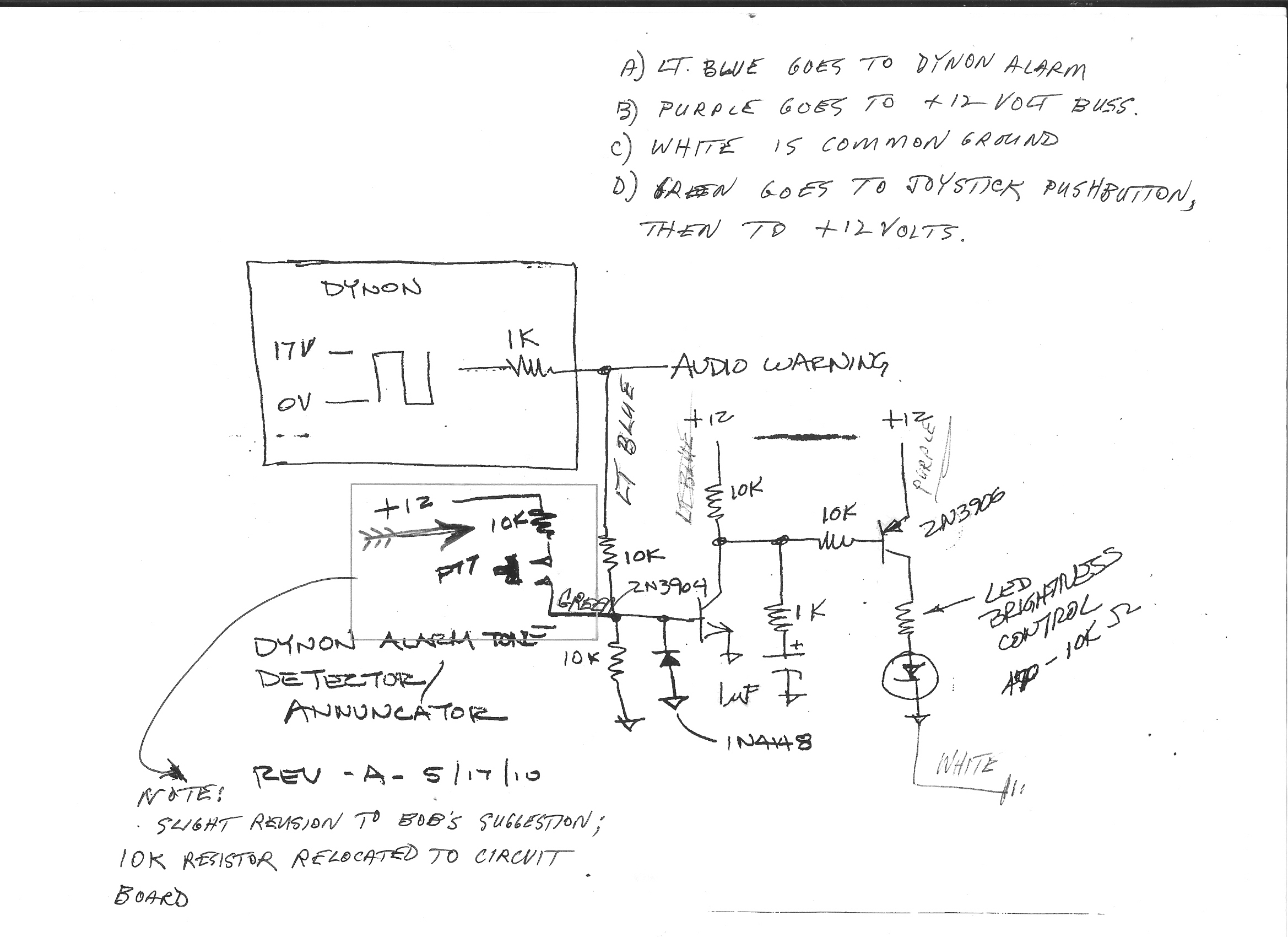
(refer to the included diagram for details)


  In testing the circuit, when it is installed in the plane, I hook up the 'always hot'

 wire to the +12volt instrument bus bar.  Next, I hook up the white wire to ground

 bus bar.  At this point, neither of the other two wires, the Dynon alarm one or the

 test wire, are hooked up to anything.

  So far, we've just got the +12volts and ground.  Plus, two OPEN circuit wires....

 one for a test switch & one for a Dynon signal, but in any event, they are identical.

 Each loose wire simply has a 10K resistor for the power to go through.  (If you

 examine the photo, I'm referring to the node underneath the "N" in the word 'green'.)


  You would think that adding a power source to either one of these circuits

 would activate the LED light & strobing LEDs circuit, right?  Nope!!  Only one of

 them works.  Remember, both of these two wires are not hooked up to anything.

 If you apply power to the light blue wire, presto, all is good.  But unhook the light

 blue wire, and then hook up the green wire, nada!!                          If I remove

 the whole thing, and take it back to the house, hook it up to the +12 volt Radio

 Shack transformer, (+&-) , and add power to either one of the loose wires, the

 green one or light blue one, it works perfect.

  The slight differences between the plane and the house tests are just enough

 to keep it from working.

Ther's something VERY sensitive between the two differing mounting places.


  BTW, you may have noted that comment I wrote in the bottom left corner of

 the page.  I added the 10K resistor from the PTT switch to inside the box, not

 outside as drawn.  I can't believe this that THIS could make a difference!!  (Picture

 placing the 10K resistor in the 'test switch' where the word 'green' is.)


  I think you are right, Vern!  Maybe lowering the resistor(s) would keep it

 from being so sensitive.  But which ones??  All of them?  Just the green wire

 one, since it can't seem to overcome some obstruction?


Thanks,  Mike W
| | - The Matronics AeroElectric-List Email Forum - | | | Use the List Feature Navigator to browse the many List utilities available such as the Email Subscriptions page, Archive Search & Download, 7-Day Browse, Chat, FAQ, Photoshare, and much more:
http://www.matronics.com/Navigator?AeroElectric-List |
|
| Description: |
|
| Filesize: |
565.76 KB |
| Viewed: |
1781 Time(s) |

|
|
|
| Back to top |
|
 |
sprocket(at)vx-aviation.c
Guest
|
 Posted: Wed Jun 01, 2011 7:10 am Post subject: Dynon Alarm circuit diagram Posted: Wed Jun 01, 2011 7:10 am Post subject: Dynon Alarm circuit diagram |
 |
|
Mike, your 12V Radio Shack transformer is probably putting out about 16  volts or more, so that may be why there is a difference.

 I would check to make sure that the diode is wired the right way.  If  wrong, you could get the flakey operation that depends on the voltage of the two  inputs.


 Vern


  From:  Mike  Welch (mdnanwelch7(at)hotmail.com)

   Sent: Wednesday, June 01, 2011 5:59 AM

 To: aeroelectric-list(at)matronics.com (aeroelectric-list(at)matronics.com)

 Subject: Dynon Alarm circuit  diagram


 List  guys,


  I got a rejected image notice from Matronics regarding  my last email.

I tried posting a tif. image, and Matronics didn't like  it.

  I'll try to repost everything properly...


Mike  W


Okay, I think I got it corrected.  Here is the email message  I sent, plus you

should see the proper formatted scan image.

Hi Vern,


(refer to the included  diagram for details)


  In testing the circuit, when it is  installed in the plane, I hook up the 'always hot'

wire to the +12volt instrument bus bar.   Next, I hook up the white wire to ground

bus bar.  At this point, neither of  the other two wires, the Dynon alarm one or the

test wire, are hooked up to anything.

   So far, we've just got the +12volts and ground.  Plus, two OPEN circuit  wires....

one for a test switch  & one for a Dynon signal, but in any event, they are identical.

Each loose wire simply has a 10K  resistor for the power to go through.  (If you

examine the photo, I'm referring to the node  underneath the "N" in the word 'green'.)


  You would think  that adding a power source to either one of these circuits

would activate the LED light & strobing LEDs  circuit, right?  Nope!!  Only one of

them works.  Remember, both of these two  wires are not hooked up to anything.

If you apply power to the light blue wire,  presto, all is good.  But unhook the light

blue wire, and then hook up the green wire,  nada!!                           If I remove

the whole thing, and  take it back to the house, hook it up to the +12 volt Radio

Shack transformer, (+&-) , and add power to  either one of the loose wires, the

green one or light blue one, it  works perfect.

  The slight differences between the plane and the house  tests are just enough

to keep it  from working.

Ther's something VERY sensitive between the two differing  mounting places.


  BTW, you may have noted that comment I  wrote in the bottom left corner of

the page.  I added the 10K resistor from the PTT switch to inside  the box, not

outside as  drawn.  I can't believe this that THIS could make a difference!!   (Picture

placing the 10K  resistor in the 'test switch' where the word 'green' is.)


  I  think you are right, Vern!  Maybe lowering the resistor(s) would keep it

from being so sensitive.   But which ones??  All of them?  Just the green wire

one, since it can't seem to overcome some  obstruction?


Thanks,  Mike W


No virus found in this  message.

Checked by AVG - www.avg.com

Version: 10.0.1375 / Virus  Database: 1509/3672 - Release Date: 05/31/11

   [quote][b]
| | - The Matronics AeroElectric-List Email Forum - | | | Use the List Feature Navigator to browse the many List utilities available such as the Email Subscriptions page, Archive Search & Download, 7-Day Browse, Chat, FAQ, Photoshare, and much more:
http://www.matronics.com/Navigator?AeroElectric-List |
|
|
|
| Back to top |
|
 |
Mike Welch
Joined: 13 Feb 2011
Posts: 272
|
 Posted: Wed Jun 01, 2011 7:59 am Post subject: Dynon Alarm circuit diagram Posted: Wed Jun 01, 2011 7:59 am Post subject: Dynon Alarm circuit diagram |
 |
|
Vern,
Radio Shack transformer is putting our precisely 13.80 volts. The instrument bus bar
in my plane is putting out 11.34 volts.
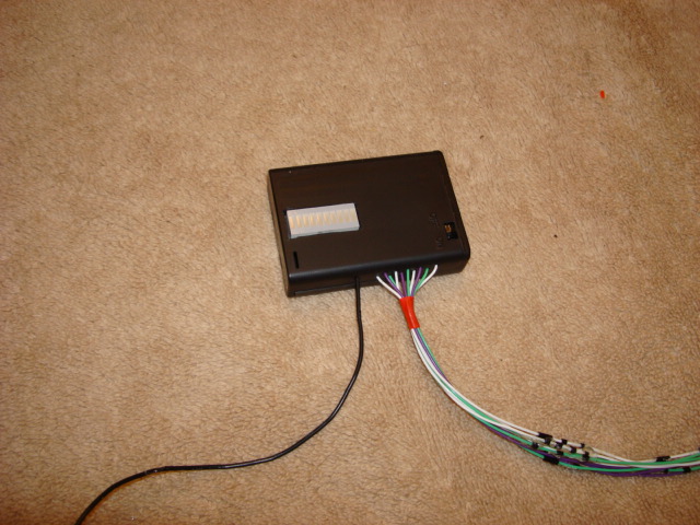
In the house, my LED test circuit is 20 pin LED DIP. (see photo)
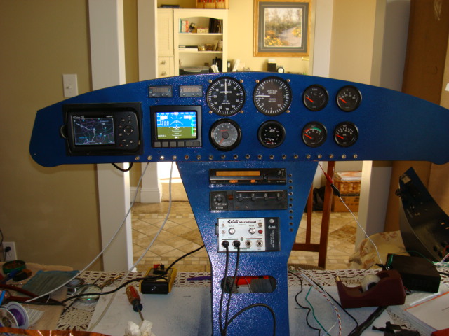
In the plane, there 19 3mm LEDs, arranged so that two at a time flash....
19&1, 18&2, 17&3, 16&4, etc, etc. strobing toward the center, ending
up at the center LED, #10 by itself. It's a lot like one of those emergency
lights you see on the highway where they strobe to the center, then repeat
about every second.
Of course, on my little 10 LED test box, it only goes one way, then repeats.
I think we may be on to something here! Since the airplane's battery voltage is
much lower than the transformer, and the airplane's LEDs are much bigger,
they're the ones that parallel the bottom edge of my panel in the photo), plus
there is a lot more of them, for some reason, there just doesn't seem to be
enough "juice" to activate the green wire, yet there IS enough to activate the
light blue wire.
Vern, and or Bob N, would swapping out those two 10K resistors that go to each
activation wire, with two 4.7K resistors hurt the design?? Maybe this would reduce the
circuits sensibilities in the plane's installation (with all the LEDs on the panel).
Maybe because the plane has a lot more (& bigger) LEDs, it needs a lot more
current. It still doesn't make sense why one wire with a 10K ohm resistor works
fine, and the other one which is identical, doesn't!!
Any thoughts on swapping those resistors, or should everyone of the 10K's be
swapped out??
Mike Welch
From: sprocket(at)vx-aviation.com
To: aeroelectric-list(at)matronics.com
Subject: Re: Dynon Alarm circuit diagram
Date: Wed, 1 Jun 2011 08:03:26 -0700
.ExternalClass .ecxhmmessage P {padding:0px;} .ExternalClass body.ecxhmmessage {font-size:10pt;font-family:Tahoma;} Mike, your 12V Radio Shack transformer is probably putting out about 16 volts or more, so that may be why there is a difference.
I would check to make sure that the diode is wired the right way. If wrong, you could get the flakey operation that depends on the voltage of the two inputs.
Vern
From: Mike Welch (mdnanwelch7(at)hotmail.com)
Sent: Wednesday, June 01, 2011 5:59 AM
To: aeroelectric-list(at)matronics.com (aeroelectric-list(at)matronics.com)
Subject: Dynon Alarm circuit diagram
List guys,
I got a rejected image notice from Matronics regarding my last email.
I tried posting a tif. image, and Matronics didn't like it.
I'll try to repost everything properly...
Mike W
Okay, I think I got it corrected. Here is the email message I sent, plus you
should see the proper formatted scan image.
Hi Vern,
(refer to the included diagram for details)
In testing the circuit, when it is installed in the plane, I hook up the 'always hot'
wire to the +12volt instrument bus bar. Next, I hook up the white wire to ground
bus bar. At this point, neither of the other two wires, the Dynon alarm one or the
test wire, are hooked up to anything.
So far, we've just got the +12volts and ground. Plus, two OPEN circuit wires....
one for a test switch & one for a Dynon signal, but in any event, they are identical.
Each loose wire simply has a 10K resistor for the power to go through. (If you
examine the photo, I'm referring to the node underneath the "N" in the word 'green'.)
You would think that adding a power source to either one of these circuits
would activate the LED light & strobing LEDs circuit, right? Nope!! Only one of
them works. Remember, both of these two wires are not hooked up to anything.
If you apply power to the light blue wire, presto, all is good. But unhook the light
blue wire, and then hook up the green wire, nada!! If I remove
the whole thing, and take it back to the house, hook it up to the +12 volt Radio
Shack transformer, (+&-) , and add power to either one of the loose wires, the
green one or light blue one, it works perfect.
The slight differences between the plane and the house tests are just enough
to keep it from working.
Ther's something VERY sensitive between the two differing mounting places.
BTW, you may have noted that comment I wrote in the bottom left corner of
the page. I added the 10K resistor from the PTT switch to inside the box, not
outside as drawn. I can't believe this that THIS could make a difference!! (Picture
placing the 10K resistor in the 'test switch' where the word 'green' is.)
I think you are right, Vern! Maybe lowering the resistor(s) would keep it
from being so sensitive. But which ones?? All of them? Just the green wire
one, since it can't seem to overcome some obstruction?
Thanks, Mike W
No virus found in this message.
Checked by AVG - www.avg.com
| Quote: |
-List" target=_blank>http://www.matronics.com/Navigator?AeroElectric-List
ttp://forums.matronics.com
=_blank>http://www.matronics.com/contribution
|
| | - The Matronics AeroElectric-List Email Forum - | | | Use the List Feature Navigator to browse the many List utilities available such as the Email Subscriptions page, Archive Search & Download, 7-Day Browse, Chat, FAQ, Photoshare, and much more:
http://www.matronics.com/Navigator?AeroElectric-List |
|
| Description: |
|
| Filesize: |
111.5 KB |
| Viewed: |
1778 Time(s) |

|
| Description: |
|
| Filesize: |
107.89 KB |
| Viewed: |
1778 Time(s) |

|
|
|
| Back to top |
|
 |
|
|
You cannot post new topics in this forum
You cannot reply to topics in this forum
You cannot edit your posts in this forum
You cannot delete your posts in this forum
You cannot vote in polls in this forum
You cannot attach files in this forum
You can download files in this forum
|
Powered by phpBB © 2001, 2005 phpBB Group
|


