 |
Matronics Email Lists
Web Forum Interface to the Matronics Email Lists
|
| View previous topic :: View next topic |
| Author |
Message |
grosseair(at)comcast.net
Guest
|
 Posted: Sun Jun 26, 2011 7:50 am Post subject: Diodes on Relays Posted: Sun Jun 26, 2011 7:50 am Post subject: Diodes on Relays |
 |
|
I understand about using diodes to protect the contacts on contactors,

but I'm wondering why we don't typically use them on smaller

electro-mechanical relays in the 20-40 amp range such as

http://www.newark.com/jsp/search/productdetail.jsp?SKU=34M8970

Is it the lower current? If so what's the point where you do or don't

need a diode across the coil contacts?


John Grosse
| | - The Matronics AeroElectric-List Email Forum - | | | Use the List Feature Navigator to browse the many List utilities available such as the Email Subscriptions page, Archive Search & Download, 7-Day Browse, Chat, FAQ, Photoshare, and much more:
http://www.matronics.com/Navigator?AeroElectric-List |
|
|
|
| Back to top |
|
 |
nuckolls.bob(at)aeroelect
Guest
|
| Posted: Sun Jun 26, 2011 8:03 am Post subject: Diodes on Relays |
|
|
At 10:46 AM 6/26/2011, you wrote:
| Quote: |
I understand about using diodes to protect the contacts on
contactors, but I'm wondering why we don't typically use them on
smaller electro-mechanical relays in the 20-40 amp range such as
http://www.newark.com/jsp/search/productdetail.jsp?SKU=34M8970
Is it the lower current? If so what's the point where you do or
don't need a diode across the coil contacts?
|
No hard and fast rule. The diode, or any other "spike suppression"
device is really an energy management tool. EVERY inductive
device has a potential for returning a bundle of stored energy
back into the system when the energizing source of current is
broken.
In some cases, that energy has the potential for (1) causing
anomalous behavior in some other system, (2) erosion of
contacts for the controlling switch, (3) damage to the
controlling solid state device . . . or some combination
of the three.
There are many cases where none of these risks are significant
and spike suppression is not part of the design. Except for
rare instances involving close control of relay operating
speed, ANY of the legacy spike suppression techniques is
useful to the task . . . and if you're in doubt, it doesn't
hurt to add it.
Bob . . .
////
(o o)
===========o00o=(_)=o00o=========
< Go ahead, make my day . . . >
< show me where I'm wrong. >
=================================
| | - The Matronics AeroElectric-List Email Forum - | | | Use the List Feature Navigator to browse the many List utilities available such as the Email Subscriptions page, Archive Search & Download, 7-Day Browse, Chat, FAQ, Photoshare, and much more:
http://www.matronics.com/Navigator?AeroElectric-List |
|
|
|
| Back to top |
|
|
nuckolls.bob(at)aeroelect
Guest
|
| Posted: Sun Jun 26, 2011 11:52 am Post subject: Diodes on Relays |
|
|
I understand about using diodes to protect the contacts on contactors, but I'm wondering why we don't typically use them on smaller electro-mechanical relays in the 20-40 amp range such as

  http://www.newark.com/jsp/search/productdetail.jsp?SKU=34M8970

 Is it the lower current? If so what's the point where you do or don't need a diode across the coil contacts?


    No hard and fast rule. The diode, or any other "spike suppression"

    device is really an energy management tool. EVERY inductive

    device has a potential for returning a bundle of stored energy

    back into the system when the energizing source of current is

    broken.


     A little elaboration . . .


     EVERY conductor of electrons has some predictable

     and measurable inductive AND capacitive component . . .

     even a lowly chunk of wire running from point A to

     point B. For wires the value of capacitance to any

     adjacent conductors manifests in PICO farads per

     foot. Inductance for a 10' length of 22awg wire is

     in the neighborhood of 30 NANO henries per foot.


     Neither characteristic's magnitude large enough

     to be significant storage reservoirs of energy.

     Now, wind say 50' of 30AWG wire around a core

     and put it inside the shell of a contactor to

     operate the armature and the ability to store energy

     takes a quantum jump.  Fabricating two conductors

     of significant area on either side of a dielectric

     material and that too creates a huge increase in

     capacitance along with an ability to store energy.


     Playing the energy management game in any system

     of interactive components is a juggling act. The

     goal is to (1) understand significant sources of

     rogue energy, (2) identify potential risks for

     letting that energy roam free in the wild and (3)

     deducing what techniques are most practical for

     keeping risks to vulnerable systems within reason.


     In some cases you can never corral all the errant

     energy, in some cases you design potentially

     vulnerable systems to shrug off potential

     antagonists at or below certain levels.


     In other words, craft a full-up system where

     there is a comfortable band of separation between

     ability to withstand versus ability to control

     the deleterious exchange of energy between systems.


     Small relays controlled by ordinary switches

     do not represent a cost of ownership/service

     life issue . . . so the designer may choose

     to leave energy mitigation devices off the

     bill of materials. At the same time, that

     exact same combination of inductance and switch

     might produce transients that are antagonistic

     to the performance of some high-speed digital

     system . . . but if the designers of systems

     at high risk for interference are doing their

     job, risks generated by the occasional operation

     of a switch on the panel are accommodated by

     design. See:


  http://tinyurl.com/ybhvxal


     My assertion for 'no hard and fast rules' was

     not intended to minimize the need for understanding

     exactly how all the ingredients for your particular

     recipe come together. The competent observer

     will take note of that 'hiccup' in display being

     coincident with operating the switch and then

     decide if there is value in changes to the recipe

     to correct the phenomenon. He will also note that

     some switch is demonstrating a poor service

     life and do something about it . . .


  http://tinyurl.com/3k6he9s


     Bob . . .     [quote][b]
| | - The Matronics AeroElectric-List Email Forum - | | | Use the List Feature Navigator to browse the many List utilities available such as the Email Subscriptions page, Archive Search & Download, 7-Day Browse, Chat, FAQ, Photoshare, and much more:
http://www.matronics.com/Navigator?AeroElectric-List |
|
|
|
| Back to top |
|
|
fvalarm(at)rapidnet.net
Guest
|
| Posted: Sun Jun 26, 2011 12:45 pm Post subject: Diodes on Relays |
|
|
Bob,


 I've recently discovered that the 20 amp relays that B&C  sells have non-polarity sensitive coil terminals.  Does this mean that  there are (steering) diodes already built into the relay?  And if so, do  these same diodes take care of the small inductive spike on  release?


 Bevan


 From:  owner-aeroelectric-list-server(at)matronics.com  [mailto:owner-aeroelectric-list-server(at)matronics.com] On Behalf Of Robert  L. Nuckolls, III

Sent: Sunday, June 26, 2011 12:49 PM

To:  aeroelectric-list(at)matronics.com

Subject: Re: Diodes  on Relays


I understand about using diodes to protect the contacts on  contactors, but I'm wondering why we don't typically use them on smaller  electro-mechanical relays in the 20-40 amp range such as

http://www.newark.com/jsp/search/productdetail.jsp?SKU=34M8970

Is  it the lower current? If so what's the point where you do or don't need a diode  across the coil contacts?


   No hard and fast rule. The diode,  or any other "spike suppression"

   device is really an energy  management tool. EVERY inductive

   device has a potential for  returning a bundle of stored energy

   back into the system when  the energizing source of current is

    broken.


    A little elaboration . .  .


    EVERY conductor of electrons has some  predictable

    and measurable inductive AND capacitive  component . . .

    even a lowly chunk of wire running from  point A to

    point B. For wires the value of capacitance to  any

    adjacent conductors manifests in PICO farads  per

    foot. Inductance for a 10' length of 22awg wire  is

    in the neighborhood of 30 NANO henries per  foot.


    Neither characteristic's magnitude large  enough

    to be significant storage reservoirs of  energy.

    Now, wind say 50' of 30AWG wire around a  core

    and put it inside the shell of a contactor  to

    operate the armature and the ability to store  energy

    takes a quantum jump.  Fabricating two  conductors

    of significant area on either side of a  dielectric

    material and that too creates a huge increase  in

    capacitance along with an ability to store  energy.


    Playing the energy management game in any  system

    of interactive components is a juggling act.  The

    goal is to (1) understand significant sources  of

    rogue energy, (2) identify potential risks  for

    letting that energy roam free in the wild and  (3)

    deducing what techniques are most practical  for

    keeping risks to vulnerable systems within  reason.


    In some cases you can never corral all the  errant

    energy, in some cases you design potentially

    vulnerable systems to shrug off  potential

    antagonists at or below certain  levels.


    In other words, craft a full-up system  where

    there is a comfortable band of separation  between

    ability to withstand versus ability to  control

    the deleterious exchange of energy between  systems.


    Small relays controlled by ordinary  switches

    do not represent a cost of  ownership/service

    life issue . . . so the designer may  choose

    to leave energy mitigation devices off  the

    bill of materials. At the same time, that

    exact same combination of inductance and  switch

    might produce transients that are  antagonistic

    to the performance of some high-speed  digital

    system . . . but if the designers of  systems

    at high risk for interference are doing  their

    job, risks generated by the occasional  operation

    of a switch on the panel are accommodated  by

    design. See:


http://tinyurl.com/ybhvxal


     My assertion for 'no hard and fast rules' was

    not intended  to minimize the need for understanding

    exactly how all the  ingredients for your particular

    recipe come together. The  competent observer

    will take note of that 'hiccup' in  display being

    coincident with operating the switch and  then

    decide if there is value in changes to the  recipe

    to correct the phenomenon. He will also note  that

    some switch is demonstrating a poor  service

    life and do something about it . . .


http://tinyurl.com/3k6he9s

    Bob . . . [quote]


href="http://www.matronics.com/Navigator?AeroElectric-List">http://www.matronics.com/Navigator?AeroElectric-List

href="http://forums.matronics.com">http://forums.matronics.com

href="http://www.matronics.com/contribution">http://www.matronics.com/c

[b]
| | - The Matronics AeroElectric-List Email Forum - | | | Use the List Feature Navigator to browse the many List utilities available such as the Email Subscriptions page, Archive Search & Download, 7-Day Browse, Chat, FAQ, Photoshare, and much more:
http://www.matronics.com/Navigator?AeroElectric-List |
|
|
|
| Back to top |
|
|
Bob McC
Joined: 09 Jan 2006
Posts: 258
Location: Toronto, ON
|
| Posted: Sun Jun 26, 2011 6:02 pm Post subject: Diodes on Relays |
|
|
Bevan;
MOST small relays are NOT polarity sensitive. For the most part, the only ones that are, are the ones containing spike suppression diodes or LED indicators. The relay coil itself doesn’t care about polarity.
The B&C relays are most likely generic basic relays without any sort of diodes such as the ones linked to by John at the start of this thread.
Bob McC
From: owner-aeroelectric-list-server(at)matronics.com [mailto:owner-aeroelectric-list-server(at)matronics.com] On Behalf Of B Tomm
Sent: Sunday, June 26, 2011 4:43 PM
To: aeroelectric-list(at)matronics.com
Subject: RE: AeroElectric-List: Diodes on Relays
Bob,
I've recently discovered that the 20 amp relays that B&C sells have non-polarity sensitive coil terminals. Does this mean that there are (steering) diodes already built into the relay? And if so, do these same diodes take care of the small inductive spike on release?
Bevan
From: owner-aeroelectric-list-server(at)matronics.com [mailto:owner-aeroelectric-list-server(at)matronics.com] On Behalf Of Robert L. Nuckolls, III
Sent: Sunday, June 26, 2011 12:49 PM
To: aeroelectric-list(at)matronics.com
Subject: Re: AeroElectric-List: Diodes on Relays
I understand about using diodes to protect the contacts on contactors, but I'm wondering why we don't typically use them on smaller electro-mechanical relays in the 20-40 amp range such as
http://www.newark.com/jsp/search/productdetail.jsp?SKU=34M8970
Is it the lower current? If so what's the point where you do or don't need a diode across the coil contacts?
No hard and fast rule. The diode, or any other "spike suppression"
device is really an energy management tool. EVERY inductive
device has a potential for returning a bundle of stored energy
back into the system when the energizing source of current is
broken.
A little elaboration . . .
EVERY conductor of electrons has some predictable
and measurable inductive AND capacitive component . . .
even a lowly chunk of wire running from point A to
point B. For wires the value of capacitance to any
adjacent conductors manifests in PICO farads per
foot. Inductance for a 10' length of 22awg wire is
in the neighborhood of 30 NANO henries per foot.
Neither characteristic's magnitude large enough
to be significant storage reservoirs of energy.
Now, wind say 50' of 30AWG wire around a core
and put it inside the shell of a contactor to
operate the armature and the ability to store energy
takes a quantum jump. Fabricating two conductors
of significant area on either side of a dielectric
material and that too creates a huge increase in
capacitance along with an ability to store energy.
Playing the energy management game in any system
of interactive components is a juggling act. The
goal is to (1) understand significant sources of
rogue energy, (2) identify potential risks for
letting that energy roam free in the wild and (3)
deducing what techniques are most practical for
keeping risks to vulnerable systems within reason.
In some cases you can never corral all the errant
energy, in some cases you design potentially
vulnerable systems to shrug off potential
antagonists at or below certain levels.
In other words, craft a full-up system where
there is a comfortable band of separation between
ability to withstand versus ability to control
the deleterious exchange of energy between systems.
Small relays controlled by ordinary switches
do not represent a cost of ownership/service
life issue . . . so the designer may choose
to leave energy mitigation devices off the
bill of materials. At the same time, that
exact same combination of inductance and switch
might produce transients that are antagonistic
to the performance of some high-speed digital
system . . . but if the designers of systems
at high risk for interference are doing their
job, risks generated by the occasional operation
of a switch on the panel are accommodated by
design. See:
http://tinyurl.com/ybhvxal
My assertion for 'no hard and fast rules' was
not intended to minimize the need for understanding
exactly how all the ingredients for your particular
recipe come together. The competent observer
will take note of that 'hiccup' in display being
coincident with operating the switch and then
decide if there is value in changes to the recipe
to correct the phenomenon. He will also note that
some switch is demonstrating a poor service
life and do something about it . . .
http://tinyurl.com/3k6he9s
Bob . . . | Quote: | | href="http://www.matronics.com/Navigator?AeroElectric-List">http://www.matronics.com/Navigator?AeroElectric-Listhref="http://forums.matronics.com">http://forums.matronics.comhref="http://www.matronics.com/contribution">http://www.matronics.com/c - The AeroElectric-List Email Forum - |
0123456789 | Quote: | | href="http://www.matronics.com/Navigator?AeroElectric-List">http://www.matronics.com/Navigator?AeroElectric-List |
0 | Quote: | | href="http://www.matronics.com/Navigator?AeroElectric-List">http://www.matronics.com/Navigator?AeroElectric-List |
1 | Quote: | | href="http://www.matronics.com/Navigator?AeroElectric-List">http://www.matronics.com/Navigator?AeroElectric-List |
2 | Quote: | | href="http://www.matronics.com/Navigator?AeroElectric-List">http://www.matronics.com/Navigator?AeroElectric-List |
3 | Quote: | | href="http://www.matronics.com/Navigator?AeroElectric-List">http://www.matronics.com/Navigator?AeroElectric-List |
4
[quote][b]
| | - The Matronics AeroElectric-List Email Forum - | | | Use the List Feature Navigator to browse the many List utilities available such as the Email Subscriptions page, Archive Search & Download, 7-Day Browse, Chat, FAQ, Photoshare, and much more:
http://www.matronics.com/Navigator?AeroElectric-List |
|
_________________
Bob McC
Falco #908
(just starting) |
|
| Back to top |
|
|
nuckolls.bob(at)aeroelect
Guest
|
| Posted: Sun Jun 26, 2011 9:24 pm Post subject: Diodes on Relays |
|
|
At 08:57 PM 6/26/2011, you wrote:
| Quote: | Bevan;
MOST small relays are NOT polarity sensitive. For the most part, the only ones that are, are the ones containing spike suppression diodes or LED indicators. The relay coil itself doesnt care about polarity.
The B&C relays are most likely generic basic relays without any sort of diodes such as the ones linked to by John at the start of this thread.
|
Correct. The only relay I used to sell that did
have the built in diode was a starter contactor . . .
and it was available either way. There was some
notation like 'coil suppression' stamped on the
bottom of the one with a diode.
I'm aware of no relays other than mil-spec devices
and a few 'upper crust' industrial relays that
commonly sport the built in suppression.
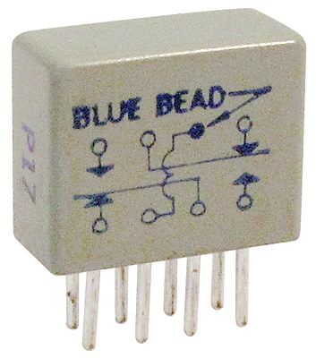
[img]cid:.0[/img]
This one clearly does not . . .
[img]cid:.1[/img]
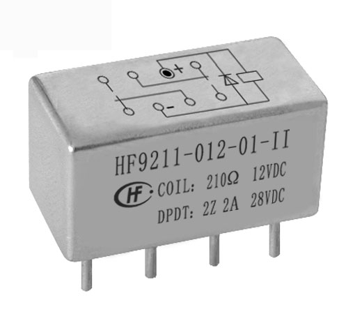
While the schematic on the enclosure for this one shows
a diode and clear (+) mark for the coil polarity.
If the relay you have in hand DOES include coil
suppression, then it will be clearly marked as such
in some manner on the outside. Otherwise, relay
coils are not polarity sensitive.
Bob . . .
| | - The Matronics AeroElectric-List Email Forum - | | | Use the List Feature Navigator to browse the many List utilities available such as the Email Subscriptions page, Archive Search & Download, 7-Day Browse, Chat, FAQ, Photoshare, and much more:
http://www.matronics.com/Navigator?AeroElectric-List |
|
| Description: |
|
| Filesize: |
108.1 KB |
| Viewed: |
3668 Time(s) |

|
| Description: |
|
| Filesize: |
47.5 KB |
| Viewed: |
3668 Time(s) |
|
|
|
| Back to top |
|
|
sprocket(at)vx-aviation.c
Guest
|
| Posted: Mon Jun 27, 2011 7:17 am Post subject: Diodes on Relays |
|
|
Iâve successfully used these automotive types with built-in supression (resistors):
http://search.digikey.com/scripts/dksearch/dksus.dll?Keywords=255-2161-ND&site=US&WT.mc_id=tbr_srch&WT.mc_ev=click

Also available with diodes, but the resistor type is polarity insensitive.
Vern
From: Robert L. Nuckolls, III (nuckolls.bob(at)aeroelectric.com)
Sent: Sunday, June 26, 2011 10:21 PM
To: aeroelectric-list(at)matronics.com (aeroelectric-list(at)matronics.com)
Subject: RE: Diodes on Relays
At 08:57 PM 6/26/2011, you wrote:
| Quote: | Bevan;
MOST small relays are NOT polarity sensitive. For the most part, the only ones that are, are the ones containing spike suppression diodes or LED indicators. The relay coil itself doesnÂt care about polarity.
The B&C relays are most likely generic basic relays without any sort of diodes such as the ones linked to by John at the start of this thread.
|
Correct. The only relay I used to sell that did
have the built in diode was a starter contactor . . .
and it was available either way. There was some
notation like 'coil suppression' stamped on the
bottom of the one with a diode.
I'm aware of no relays other than mil-spec devices
and a few 'upper crust' industrial relays that
commonly sport the built in suppression.
[img]cid:4D7B85A593F2463C8EA61888B6BDC03B(at)Sprocket[/img]
This one clearly does not . . .
[img]cid:CDFAA29602B54E8BBB7E7AA3B1D4A9CD(at)Sprocket[/img]
While the schematic on the enclosure for this one shows
a diode and clear (+) mark for the coil polarity.
If the relay you have in hand DOES include coil
suppression, then it will be clearly marked as such
in some manner on the outside. Otherwise, relay
coils are not polarity sensitive.
Bob . . .
No virus found in this message.
Checked by AVG - www.avg.com
Version: 10.0.1388 / Virus Database: 1513/3728 - Release Date: 06/26/11
| | - The Matronics AeroElectric-List Email Forum - | | | Use the List Feature Navigator to browse the many List utilities available such as the Email Subscriptions page, Archive Search & Download, 7-Day Browse, Chat, FAQ, Photoshare, and much more:
http://www.matronics.com/Navigator?AeroElectric-List |
|
| Description: |
|
| Filesize: |
108.1 KB |
| Viewed: |
3652 Time(s) |
|
| Description: |
|
| Filesize: |
47.5 KB |
| Viewed: |
3652 Time(s) |

|
|
|
| Back to top |
|
|
|
|
You cannot post new topics in this forum
You cannot reply to topics in this forum
You cannot edit your posts in this forum
You cannot delete your posts in this forum
You cannot vote in polls in this forum
You cannot attach files in this forum
You can download files in this forum
|
Powered by phpBB © 2001, 2005 phpBB Group
|

