 |
Matronics Email Lists
Web Forum Interface to the Matronics Email Lists
|
| View previous topic :: View next topic |
| Author |
Message |
stuart(at)stuarthutchison
Guest
|
 Posted: Tue Jun 28, 2011 6:36 am Post subject: Tiny solder tab Posted: Tue Jun 28, 2011 6:36 am Post subject: Tiny solder tab |
 |
|
G'day Bob,


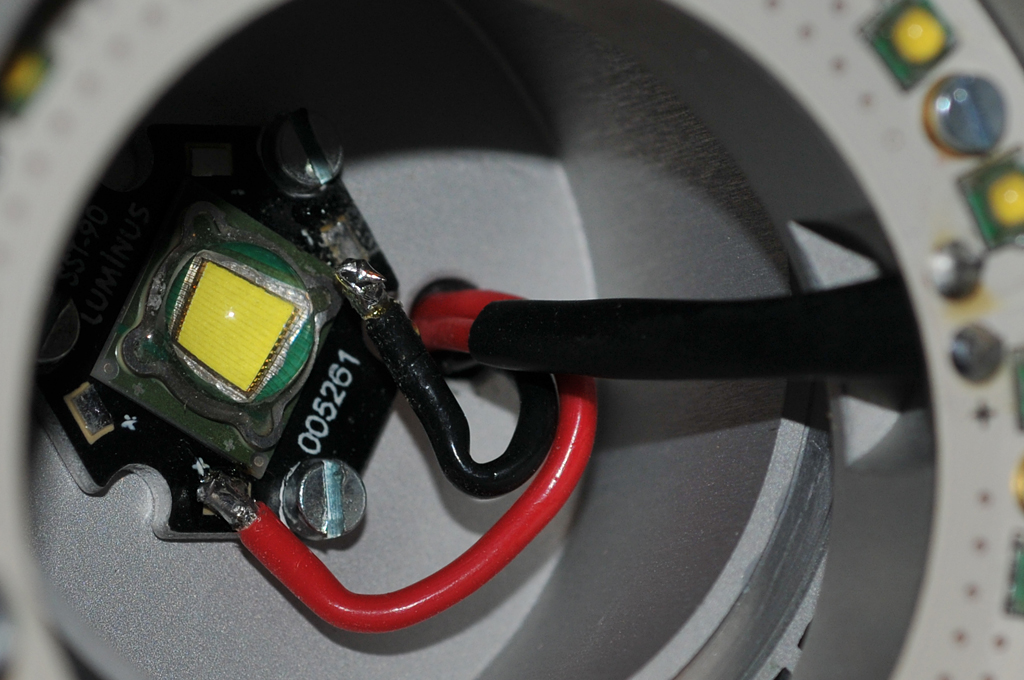
 I have a tiny  soldering job to do because the return wire shown in the photo has separated  from the LED solder tab.  The LED OEM (Luminus) data sheet says that the  used and spare cathode (just visible at the top of the LED base) are  interconnected, but there would be more strain on the main wire to reach  the spare solder tab.  Perhaps a small jumper between the first and  second cathode (and same for the anodes) would be smart too, but I need to  re-attach the wire without damaging the LED.  I have some ideas about how to provide strain  relief and protection for the wires Bob, but what do you think is the best  way to prepare and re-solder to this tiny solder tab, which is only about 1/16 x  1/8" in size?  For reference, the screws are  M3.


 Cheers,  Stu
| | - The Matronics AeroElectric-List Email Forum - | | | Use the List Feature Navigator to browse the many List utilities available such as the Email Subscriptions page, Archive Search & Download, 7-Day Browse, Chat, FAQ, Photoshare, and much more:
http://www.matronics.com/Navigator?AeroElectric-List |
|
| Description: |
|
| Filesize: |
443.59 KB |
| Viewed: |
1764 Time(s) |

|
| Description: |
|
| Filesize: |
367.09 KB |
| Viewed: |
1764 Time(s) |

|
|
|
| Back to top |
|
 |
nuckolls.bob(at)aeroelect
Guest
|
 Posted: Tue Jun 28, 2011 7:10 am Post subject: Tiny solder tab Posted: Tue Jun 28, 2011 7:10 am Post subject: Tiny solder tab |
 |
|
At 09:32 AM 6/28/2011, you wrote:
| Quote: | G'day Bob,
I have a tiny soldering job to do because the return wire shown in the photo has separated from the LED solder tab. The LED OEM (Luminus) data sheet says that the used and spare cathode (just visible at the top of the LED base) are interconnected, but there would be more strain on the main wire to reach the spare solder tab. Perhaps a small jumper between the first and second cathode (and same for the anodes) would be smart too, but I need to re-attach the wire without damaging the LED. I have some ideas about how to provide strain relief and protection for the wires Bob, but what do you think is the best way to prepare and re-solder to this tiny solder tab, which is only about 1/16 x 1/8" in size? For reference, the screws are M3. |
What AWG are these wires? How much current does
the LED draw?
The first idea that comes to mind is replacing the
wires with smaller gage still sufficient to the
current. I'd bet you can go down to 24 or perhaps
26AWG. Remove all the existing 'fat' wires and
bring smaller leads to the outside of the enclosure.
Use some form of adhesive/sealant to secure the wires
as they pass through the housing.
Once in the more robust, outside world, figure out
some form of connector . . . or perhaps splice to
more robust leads and secure the joint mechanically
under a band-clamp.
You need a soldering iron with a small tip and some
63/37 solder. I'd clean off the pads with a piece
of solder-wick, re-tin the pads with small dots of
solder. Tin the ends of wires to be attached. Then
'tack' the wires onto the pads.
Bob . . . [quote][b]
| | - The Matronics AeroElectric-List Email Forum - | | | Use the List Feature Navigator to browse the many List utilities available such as the Email Subscriptions page, Archive Search & Download, 7-Day Browse, Chat, FAQ, Photoshare, and much more:
http://www.matronics.com/Navigator?AeroElectric-List |
|
|
|
| Back to top |
|
 |
rv8iator(at)gmail.com
Guest
|
 Posted: Tue Jun 28, 2011 7:46 am Post subject: Tiny solder tab Posted: Tue Jun 28, 2011 7:46 am Post subject: Tiny solder tab |
 |
|
Stu,


If that's a MCPCB (metal core printed circuit bard, typically aluminum) you will need to preheat the board (and LED) on a hot plate to properly solder to the pad.  Without heating the board you will never get the solder to flow on the pad.  At work we build hundreds of these type of LED assemblies.  We set our hotplate to 150° C and use 63/37 Pb/Sn solder.  Place the MCPCB on the hotplate.  Place a small piece of solder on the pad.  Bring the tinned wire and soldering iron tip in contact with the pad.  The solder should flow freely.  Remove the solder iron and the solder should re-solidify on the pad with the wire embedded. Remove the assembly from the hotplate.


Chris Stone

RV-8

OR

On Tue, Jun 28, 2011 at 7:32 AM, Stuart Hutchison <stuart(at)stuarthutchison.com.au (stuart(at)stuarthutchison.com.au)> wrote:

 [quote]     G'day Bob,


 I have a tiny  soldering job to do because the return wire shown in the photo has separated  from the LED solder tab.  The LED OEM (Luminus) data sheet says that the  used and spare cathode (just visible at the top of the LED base) are  interconnected, but there would be more strain on the main wire to reach  the spare solder tab.  Perhaps a small jumper between the first and  second cathode (and same for the anodes) would be smart too, but I need to  re-attach the wire without damaging the LED.  I have some ideas about how to provide strain  relief and protection for the wires Bob, but what do you think is the best  way to prepare and re-solder to this tiny solder tab, which is only about 1/16 x  1/8" in size?  For reference, the screws are  M3.


 Cheers,  Stu


 [b]
| | - The Matronics AeroElectric-List Email Forum - | | | Use the List Feature Navigator to browse the many List utilities available such as the Email Subscriptions page, Archive Search & Download, 7-Day Browse, Chat, FAQ, Photoshare, and much more:
http://www.matronics.com/Navigator?AeroElectric-List |
|
|
|
| Back to top |
|
 |
stuart(at)stuarthutchison
Guest
|
 Posted: Wed Jun 29, 2011 4:56 am Post subject: Tiny solder tab Posted: Wed Jun 29, 2011 4:56 am Post subject: Tiny solder tab |
 |
|
Thanks Bob and Chris.
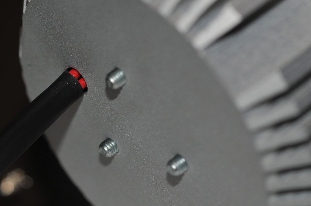
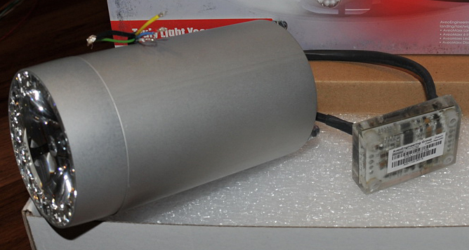
Yes, I reckon the wires are about 16 AWG and the current draw is said to be about 3.15A for the landing light part of the new AveoMaxx 6-in-1. I would return it for repair under warranty, but Aveo voided that because I removed three screws holding the front lens in place. I was trying to look for an obvious fault and also see how the 'beam angle adjustment' works, but there is none. After exiting the body, the wires are soldered to the control circuit board, which is embedded in epoxy. I'll put some thought into how to heat the board as Chris suggested and give it a go. Mouser Electronics sell the LEDS for about $50 each if I screw it up.
Cheers, Stu
From: owner-aeroelectric-list-server(at)matronics.com [mailto:owner-aeroelectric-list-server(at)matronics.com] On Behalf Of Robert L. Nuckolls, III
Sent: Wednesday, June 29, 2011 1:07 AM
To: aeroelectric-list(at)matronics.com
Subject: Re: Tiny solder tab
At 09:32 AM 6/28/2011, you wrote:
| Quote: | G'day Bob,
I have a tiny soldering job to do because the return wire shown in the photo has separated from the LED solder tab. The LED OEM (Luminus) data sheet says that the used and spare cathode (just visible at the top of the LED base) are interconnected, but there would be more strain on the main wire to reach the spare solder tab. Perhaps a small jumper between the first and second cathode (and same for the anodes) would be smart too, but I need to re-attach the wire without damaging the LED. I have some ideas about how to provide strain relief and protection for the wires Bob, but what do you think is the best way to prepare and re-solder to this tiny solder tab, which is only about 1/16 x 1/8" in size? For reference, the screws are M3. |
What AWG are these wires? How much current does
the LED draw?
The first idea that comes to mind is replacing the
wires with smaller gage still sufficient to the
current. I'd bet you can go down to 24 or perhaps
26AWG. Remove all the existing 'fat' wires and
bring smaller leads to the outside of the enclosure.
Use some form of adhesive/sealant to secure the wires
as they pass through the housing.
Once in the more robust, outside world, figure out
some form of connector . . . or perhaps splice to
more robust leads and secure the joint mechanically
under a band-clamp.
You need a soldering iron with a small tip and some
63/37 solder. I'd clean off the pads with a piece
of solder-wick, re-tin the pads with small dots of
solder. Tin the ends of wires to be attached. Then
'tack' the wires onto the pads.
Bob . . . | Quote: |
href="http://www.matronics.com/Navigator?AeroElectric-List">http://www.matronics.com/Navigator?AeroElectric-List
href="http://forums.matronics.com">http://forums.matronics.com
href="http://www.matronics.com/contribution">http://www.matronics.com/c
|
| | - The Matronics AeroElectric-List Email Forum - | | | Use the List Feature Navigator to browse the many List utilities available such as the Email Subscriptions page, Archive Search & Download, 7-Day Browse, Chat, FAQ, Photoshare, and much more:
http://www.matronics.com/Navigator?AeroElectric-List |
|
| Description: |
|
| Filesize: |
188.71 KB |
| Viewed: |
1749 Time(s) |

|
|
|
| Back to top |
|
 |
nuckolls.bob(at)aeroelect
Guest
|
 Posted: Wed Jun 29, 2011 6:39 am Post subject: Tiny solder tab Posted: Wed Jun 29, 2011 6:39 am Post subject: Tiny solder tab |
 |
|
At 07:53 AM 6/29/2011, you wrote:
| Quote: | Thanks Bob and Chris.
Yes, I reckon the wires are about 16 AWG and the current draw is said to be about 3.15A for the landing light part of the new AveoMaxx 6-in-1. |
Okay, you can drop the wire to 22AWG and make the job
MUCH easier. To have come from the factory with such
fat wire is mystifying . . .
| Quote: | | I would return it for repair under warranty, but Aveo voided that because I removed three screws holding the front lens in place. I was trying to look for an obvious fault and also see how the 'beam angle adjustment' works, but there is none. After exiting the body, the wires are soldered to the control circuit board, which is embedded in epoxy. I'll put some thought into how to heat the board as Chris suggested and give it a go. Mouser Electronics sell the LEDS for about $50 each if I screw it up. |
Okay, you've not bounded your risks. $50 + time to
do the experiment is not the upper limit . . .
if you 'screw it up' it may be because you don't
have the tools and techniques which the factory does
have. An out-of-warranty repair might be cheaper
than a new LED assy and the risks for lack of
tools and process go to zero.
I'd sure talk to the factory first . . . and ask
them, "why 16AWG lead wires?" in a 5A or less
circuit.
Bob . . . [quote][b]
| | - The Matronics AeroElectric-List Email Forum - | | | Use the List Feature Navigator to browse the many List utilities available such as the Email Subscriptions page, Archive Search & Download, 7-Day Browse, Chat, FAQ, Photoshare, and much more:
http://www.matronics.com/Navigator?AeroElectric-List |
|
|
|
| Back to top |
|
 |
|
|
You cannot post new topics in this forum
You cannot reply to topics in this forum
You cannot edit your posts in this forum
You cannot delete your posts in this forum
You cannot vote in polls in this forum
You cannot attach files in this forum
You can download files in this forum
|
Powered by phpBB © 2001, 2005 phpBB Group
|


