 |
Matronics Email Lists
Web Forum Interface to the Matronics Email Lists
|
| View previous topic :: View next topic |
| Author |
Message |
messydeer
Joined: 13 Feb 2006
Posts: 214
Location: Bellingham, WA
|
 Posted: Sun Nov 20, 2011 9:13 am Post subject: PTT Y adapter for RST intercom Posted: Sun Nov 20, 2011 9:13 am Post subject: PTT Y adapter for RST intercom |
 |
|
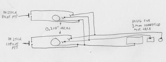
I just got an old RST intercom that I plan to use with a Dynon DX-15 handheld radio. There were a couple stand alone PTT switches with velcro attachments for the buttons that came with the intercom, but I'd rather use my in-stick switches that I'm making.


It looks like I could make a Y adapter with a couple 0.210" jacks and whatever sized plug fits the radio mic jack. I haven't got the radio yet, but the Dynon manual says this jack is 3 mm and the speaker jack is 2.5 mm.


It looks like I could terminate the wires from one .210" jack into the terminals of the other jack, instead of splicing them outside the unit as my drawing shows.


I have some 2-conductor shielded cable. Could I use this and connect the shield to the sleeves?
| | - The Matronics AeroElectric-List Email Forum - | | | Use the List Feature Navigator to browse the many List utilities available such as the Email Subscriptions page, Archive Search & Download, 7-Day Browse, Chat, FAQ, Photoshare, and much more:
http://www.matronics.com/Navigator?AeroElectric-List |
|
| Description: |
|
| Filesize: |
347.44 KB |
| Viewed: |
37130 Time(s) |
|
| Description: |
|
| Filesize: |
14.86 KB |
| Viewed: |
37130 Time(s) |
|
_________________
Dan |
|
| Back to top |
|
 |
nuckolls.bob(at)aeroelect
Guest
|
 Posted: Sun Nov 20, 2011 10:27 am Post subject: PTT Y adapter for RST intercom Posted: Sun Nov 20, 2011 10:27 am Post subject: PTT Y adapter for RST intercom |
 |
|
At 11:13 AM 11/20/2011, you wrote:
| Quote: | --> AeroElectric-List message posted by: "messydeer" <messydeer(at)yahoo.com>
I just got an old RST intercom that I plan to use with a Dynon DX-15 handheld radio. There were a couple stand alone PTT switches with velcro attachments for the buttons that came with the intercom, but I'd rather use my in-stick switches that I'm making.
It looks like I could make a Y adapter with a couple 0.210" jacks and whatever sized plug fits the radio mic jack. I haven't got the radio yet, but the Dynon manual says this jack is 3 mm and the speaker jack is 2.5 mm.
It looks like I could terminate the wires from one .210" jack into the terminals of the other jack, instead of splicing them outside the unit as my drawing shows.
I have some 2-conductor shielded cable. Could I use this and connect the shield to the sleeves? |
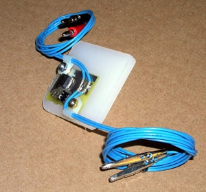
You only need two conductors total . . . a ptt and
ground lead. Shielding is not necessary but shielded
wires can offer some conveniences. My low ohms adapters
[img]cid:7.1.0.9.0.20111120121441.04560db8(at)aeroelectric.com.0[/img]
Use shielded wire for convenience of assembly and
nice 'round' lead wires as opposed to the spiral
lumpiness of a twisted pair.
You can parallel as many PTT buttons as you
wish. You will find that the ground side
of the PTT line shares a ground side of
the mic audio both tied to the shell of
the plug or jack. See Mic jack wiring in
http://www.aeroelectric.com/PPS/Audio/DualCommAudio.pdf
Bob . . .
| | - The Matronics AeroElectric-List Email Forum - | | | Use the List Feature Navigator to browse the many List utilities available such as the Email Subscriptions page, Archive Search & Download, 7-Day Browse, Chat, FAQ, Photoshare, and much more:
http://www.matronics.com/Navigator?AeroElectric-List |
|
| Description: |
|
| Filesize: |
68.62 KB |
| Viewed: |
37125 Time(s) |
|
|
|
| Back to top |
|
 |
messydeer
Joined: 13 Feb 2006
Posts: 214
Location: Bellingham, WA
|
 Posted: Sun Nov 20, 2011 5:42 pm Post subject: Re: PTT Y adapter for RST intercom Posted: Sun Nov 20, 2011 5:42 pm Post subject: Re: PTT Y adapter for RST intercom |
 |
|
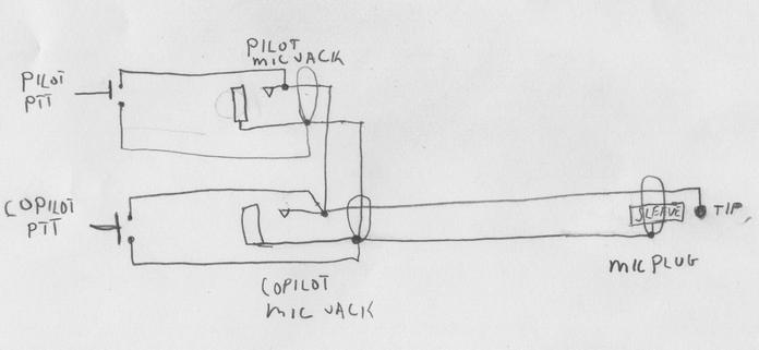
Yes, two conductors only. Shield as one, center wire as the other. I realize now the ring lead didn't connect to anything in my first drawing. I cleaned things up a bit in the reworked drawing below. Is this what you mean?
| | - The Matronics AeroElectric-List Email Forum - | | | Use the List Feature Navigator to browse the many List utilities available such as the Email Subscriptions page, Archive Search & Download, 7-Day Browse, Chat, FAQ, Photoshare, and much more:
http://www.matronics.com/Navigator?AeroElectric-List |
|
| Description: |
|
| Filesize: |
20.17 KB |
| Viewed: |
37110 Time(s) |
|
_________________
Dan |
|
| Back to top |
|
 |
nuckolls.bob(at)aeroelect
Guest
|
 Posted: Sun Nov 20, 2011 6:09 pm Post subject: PTT Y adapter for RST intercom Posted: Sun Nov 20, 2011 6:09 pm Post subject: PTT Y adapter for RST intercom |
 |
|
At 07:42 PM 11/20/2011, you wrote:
| Quote: |
Yes, two conductors only. Shield as one, center wire as the other. I
realize now the ring lead didn't connect to anything in my first
drawing. I cleaned things up a bit in the reworked drawing below. Is
this what you mean?\
|
The jacks depicted don't show any microphone wiring . . . are
these jacks wire for mic too? Keep in mind that PTT goes
to the tip connector of the conventional, .205" microphone
plug.
http://aeroelectric.com/articles/micjack/micjack.html
Bob . . .
| | - The Matronics AeroElectric-List Email Forum - | | | Use the List Feature Navigator to browse the many List utilities available such as the Email Subscriptions page, Archive Search & Download, 7-Day Browse, Chat, FAQ, Photoshare, and much more:
http://www.matronics.com/Navigator?AeroElectric-List |
|
|
|
| Back to top |
|
 |
messydeer
Joined: 13 Feb 2006
Posts: 214
Location: Bellingham, WA
|
 Posted: Sun Nov 20, 2011 7:11 pm Post subject: Re: PTT Y adapter for RST intercom Posted: Sun Nov 20, 2011 7:11 pm Post subject: Re: PTT Y adapter for RST intercom |
 |
|
| Quote: | The jacks depicted don't show any microphone wiring . . . are
these jacks wire for mic too? |
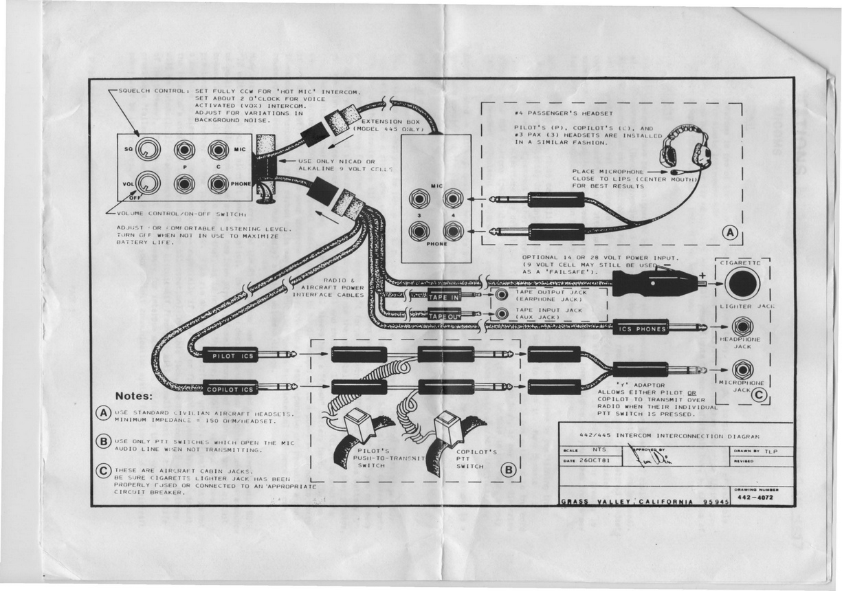
Do you mean headphone wiring? I left out the headphone wiring, cuz I'd plug my headset mic and phone plugs into the RST intercom box. According to the RST diagram, the lead from this box labeled 'ics phones' would get plugged into the handheld headphone jack.
What I'm trying to replace is the PTT wiring, labeled 'B' in this diagram, so I intended to depict the two PTT switches, the two mic jacks, and the single mic plug. I erased the ring connections in my drawing, leaving just the shell and tip connects for the plugs.
| Quote: | Keep in mind that PTT goes
to the tip connector of the conventional, .205" microphone
plug. |
I also noticed in the micjack.html article the mic jacks have ring terminals that are connected to the pilot and copilot mic hi leads of the 760 radio, while in another drawing of yours, http://www.aeroelectric.com/PPS/Audio/hv1_760vhf.pdf you show these mic jacks with nothing connected to them.
| | - The Matronics AeroElectric-List Email Forum - | | | Use the List Feature Navigator to browse the many List utilities available such as the Email Subscriptions page, Archive Search & Download, 7-Day Browse, Chat, FAQ, Photoshare, and much more:
http://www.matronics.com/Navigator?AeroElectric-List |
|
_________________
Dan |
|
| Back to top |
|
 |
nuckolls.bob(at)aeroelect
Guest
|
 Posted: Mon Nov 21, 2011 7:00 am Post subject: PTT Y adapter for RST intercom Posted: Mon Nov 21, 2011 7:00 am Post subject: PTT Y adapter for RST intercom |
 |
|
I erased the ring connections in my drawing, leaving just the shell and tip connects for the plugs.


    Understand. My comment was based on the fact that microphone

    jacks were depicted with only two connections.


   In the drawings I publish . . .


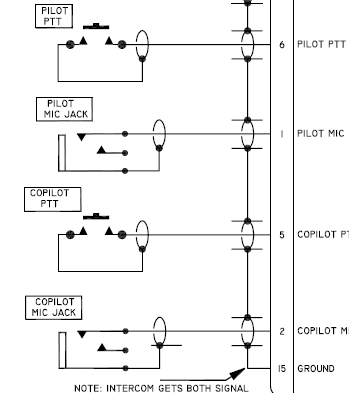
 [img]cid:.0[/img]


    A microphone jack is drawn with all available connections

    so that it is clear which connections are or are not

    used. Note that the schematic emulates the position of

    the connection along the barrel axis of the plug. The connection

    closest to the jack's mounting is the sleeve (mic) and

    furthest away is the tip (ptt). In the drawings where

    PTT is not connected, PTT functions are addressed

    elsewhere as in the snapshot above. If only PTT connections

    are used, then mic audio functions have to be addressed

    elsewhere.


    My comment was only a reaction to seeing a "mic jack"

    with two available connections. If you hand this

    to a technician along with the mic jack and say, "Here,

    wire this up," then there is a possibility of

    error or further questions to address.


    Schematics are a bit of a hot-button with me. I

    think they should be jump-off-the-page self

    explanatory. I was editing a service manual on

    the Cessna Nav-O-Matic 400 Autopilot as a tech

    writer about 1967. It was the first time I encountered

    a progressive transfer switch in a product.

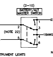
    It took me some time to figure out how the thing

    worked because the symbology did not describe the

    function. I crafted this symbol and put it into

    the autopilot control head schematic . . .


 [img]cid:.1[/img]


    My supervisor jumped all over me for departing

    from the ". . . accepted way of depicting the

    switch. After all the guys who designed the autopilot

    certainly had a lot more mo-jo than a 24 year

    old tech writer . . ."


    I had to take the argument up to the chief

    electrical engineer to get it blessed. To my

    knowledge, that is the first time a progressive

    transfer function was accurately depicted

    schematically in a publication.


 I also noticed in the micjack.html  article the mic jacks have ring terminals that are connected to the pilot and copilot mic hi leads of the 760 radio, while in another drawing of yours,  http://www.aeroelectric.com/PPS/Audio/hv1_760vhf.pdf you show these mic jacks with nothing connected to them.


    In the excerpt above, look at the position of the

    connections along the axis of plug. Those mic jacks

    are for audio only. I.e. no hand-held microphones

    with PTT switches. PTT functions are managed elsewhere

    and only the ring terminal is utilized in the jack.


    When you 'erased the ring connections' your schematic

    lost clarity.


    Bob . . .
| | - The Matronics AeroElectric-List Email Forum - | | | Use the List Feature Navigator to browse the many List utilities available such as the Email Subscriptions page, Archive Search & Download, 7-Day Browse, Chat, FAQ, Photoshare, and much more:
http://www.matronics.com/Navigator?AeroElectric-List |
|
| Description: |
|
| Filesize: |
42.12 KB |
| Viewed: |
37088 Time(s) |
|
| Description: |
|
| Filesize: |
19.19 KB |
| Viewed: |
37088 Time(s) |
|
|
|
| Back to top |
|
 |
messydeer
Joined: 13 Feb 2006
Posts: 214
Location: Bellingham, WA
|
 Posted: Mon Nov 21, 2011 7:45 am Post subject: Re: PTT Y adapter for RST intercom Posted: Mon Nov 21, 2011 7:45 am Post subject: Re: PTT Y adapter for RST intercom |
 |
|
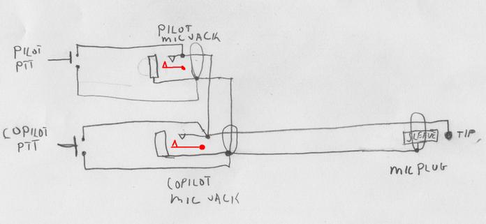
Understand the importance of making drawings clear, thanks. I added the missing ring terminal, which is left unconnected. In published drawings, the mic jacks leave the tip unconnected, but I went according to your PTT adapter hand drawing. I couldn't find it on your site so posted a renamed copy of it here.


Is my wiring drawing now correct, so that it'll work how I intend it?


I've also seen some diagrams labeled 'HI' and 'LO'. What's this all about?
| | - The Matronics AeroElectric-List Email Forum - | | | Use the List Feature Navigator to browse the many List utilities available such as the Email Subscriptions page, Archive Search & Download, 7-Day Browse, Chat, FAQ, Photoshare, and much more:
http://www.matronics.com/Navigator?AeroElectric-List |
|
| Description: |
|
| Filesize: |
20.7 KB |
| Viewed: |
37077 Time(s) |
|
| Description: |
|

Download |
| Filename: |
Push-to-Talk_Adapter ptt.pdf |
| Filesize: |
17.12 KB |
| Downloaded: |
602 Time(s) |
_________________
Dan |
|
| Back to top |
|
 |
nuckolls.bob(at)aeroelect
Guest
|
 Posted: Mon Nov 21, 2011 8:35 am Post subject: PTT Y adapter for RST intercom Posted: Mon Nov 21, 2011 8:35 am Post subject: PTT Y adapter for RST intercom |
 |
|
At 09:45 AM 11/21/2011, you wrote:
| Quote: |
Understand the importance of making drawings clear, thanks. I added
the missing ring terminal, which is left unconnected. In published
drawings, the mic jacks leave the tip unconnected, but I went
according to your PTT adapter hand drawing. I couldn't find it on
your site so posted a renamed copy of it here.
Is my wiring drawing now correct, so that it'll work how I intend it?
|
That will work . . .
| Quote: | I've also seen some diagrams labeled 'HI' and 'LO'. What's this all about?
|
That's an artifact from the world of balanced audio
signals where there was value in denoting polarity
or phase where neither signal lead was a ground.
+ and - seemed good for DC signals but didn't make
sense for AC . . . so HI and LO were adopted. This
carried over into some unbalanced signal circuits
where "LO" is really signal ground and "HI" is the
information path.
Bob . . .
| | - The Matronics AeroElectric-List Email Forum - | | | Use the List Feature Navigator to browse the many List utilities available such as the Email Subscriptions page, Archive Search & Download, 7-Day Browse, Chat, FAQ, Photoshare, and much more:
http://www.matronics.com/Navigator?AeroElectric-List |
|
|
|
| Back to top |
|
 |
messydeer
Joined: 13 Feb 2006
Posts: 214
Location: Bellingham, WA
|
 Posted: Mon Nov 21, 2011 9:28 pm Post subject: Re: PTT Y adapter for RST intercom Posted: Mon Nov 21, 2011 9:28 pm Post subject: Re: PTT Y adapter for RST intercom |
 |
|
| Quote: | | "LO" is really signal ground |
Wish I woulda asked earlier. Makes the diagrams less confusing.
I need to make sure I understand how a PTT circuit works. Lemme start with a panel mount radio. The two I've seen have dedicated terminals labeled 'PTT'. This circuit is normally open, but when the PTT button on the stick is pushed, a ground path is completed. This causes the radio to transmit. In the Microair 760, it looks like pushing either one of the parallel connected PTT buttons would transmit both mics, since they're both connected to the same PTT terminal on the radio. If this is correct, then I've understood it well enough to wire a panel mounted radio.
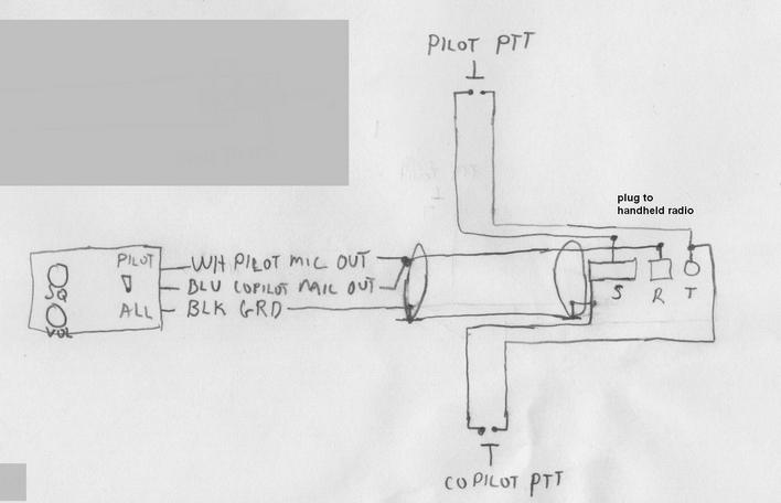
But I am getting a Dynon DX15 handheld radio and already have an RST 442 intercom to install. I just noticed earlier today you have wiring diagrams for this, http://www.aeroelectric.com/Installation_Data/RST/RST-442.pdf I've disassembled the RST intercom chasis and plan to mount just the squelch and volume controls and the all/pilot toggle switch on the panel and run the mic and phone leads to the permanently mounted mic and phone jacks in the panel.
I plan to connect the mic out wires from the RST chassis behind my panel to the handheld radio, with PTT switches in between them. So I tweaked the design a little to allow for direct wiring instead of using the clunky plugs and jacks supplied with the RST unit. With the system I have drawn, pushing either PTT button would make both mics transmit, right?
| | - The Matronics AeroElectric-List Email Forum - | | | Use the List Feature Navigator to browse the many List utilities available such as the Email Subscriptions page, Archive Search & Download, 7-Day Browse, Chat, FAQ, Photoshare, and much more:
http://www.matronics.com/Navigator?AeroElectric-List |
|
| Description: |
|
| Filesize: |
25.81 KB |
| Viewed: |
37050 Time(s) |
|
_________________
Dan |
|
| Back to top |
|
 |
messydeer
Joined: 13 Feb 2006
Posts: 214
Location: Bellingham, WA
|
 Posted: Wed Nov 23, 2011 1:07 pm Post subject: Re: PTT Y adapter for RST intercom Posted: Wed Nov 23, 2011 1:07 pm Post subject: Re: PTT Y adapter for RST intercom |
 |
|
I read this in the RST 442 documentation this morning:


Some push-to-transmit switches are designed only for use with headsets and radios and leave the

microphone audio line (this is the "ring" portion of the microphone plug) connected to the radio even

when the radio is not transmitting. Since some radios ground (disable) the microphone audio in receive

mode, this type of PTT switch is unsuitable for use with an intercom system. If you already have PTT

switches in the aircraft you may wish to try them with your intercom. If, however, you find that you

lose intercom function (microphones are weak, distorted, or dead) when you plug the "PILOT ICS" and

"COPILOT ICS" plugs into the COM radio via these PTT switches you will need to either 1) change to a

model switch which opens the audio line when not transmitting or 2) consult your local radio shop and

have a relay installed to achieve the same effect.


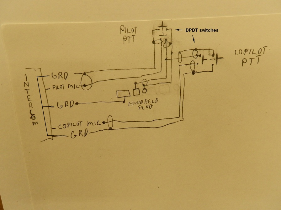
I found out my Dynon DX15 handheld radio sends power to the mic only when transmitting, so my last schematic wouldn't work. They suggested using DPDT switches for the PTT's. Unfortunately, the gatekeeper to the engineer I was corresponding with has cut me off, so I can't get any more answers from them.


I drew what I hope will work for me. I would use 4 pieces of single conductor shielded wire with the braided shield carrying ground current. The intercom has extra ground wires coming out of it, so that's already set. An additional unshielded ground wire would go from the intercom to the shell of the plug to the handheld radio.


How does this look?


BTW, is it common for radios to operate this way?
| | - The Matronics AeroElectric-List Email Forum - | | | Use the List Feature Navigator to browse the many List utilities available such as the Email Subscriptions page, Archive Search & Download, 7-Day Browse, Chat, FAQ, Photoshare, and much more:
http://www.matronics.com/Navigator?AeroElectric-List |
|
| Description: |
|
| Filesize: |
134.09 KB |
| Viewed: |
37030 Time(s) |
|
_________________
Dan |
|
| Back to top |
|
 |
Bob McC
Joined: 09 Jan 2006
Posts: 258
Location: Toronto, ON
|
 Posted: Wed Nov 23, 2011 8:54 pm Post subject: PTT Y adapter for RST intercom Posted: Wed Nov 23, 2011 8:54 pm Post subject: PTT Y adapter for RST intercom |
 |
|
Not quite following you here. You've stated you're using DPDT switches for

the PTT but you've depicted DPST in your sketch???


Bob McC


[quote] --
| | - The Matronics AeroElectric-List Email Forum - | | | Use the List Feature Navigator to browse the many List utilities available such as the Email Subscriptions page, Archive Search & Download, 7-Day Browse, Chat, FAQ, Photoshare, and much more:
http://www.matronics.com/Navigator?AeroElectric-List |
|
_________________
Bob McC
Falco #908
(just starting) |
|
| Back to top |
|
 |
messydeer
Joined: 13 Feb 2006
Posts: 214
Location: Bellingham, WA
|
 Posted: Wed Nov 23, 2011 9:35 pm Post subject: Re: PTT Y adapter for RST intercom Posted: Wed Nov 23, 2011 9:35 pm Post subject: Re: PTT Y adapter for RST intercom |
 |
|
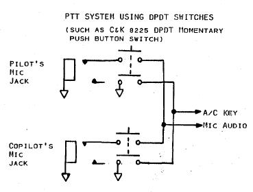
Hmm...I didn't think if they were or weren't single or double throws. Here's Dynon's quote:


"I took a look at your schematic and I don't think this configuration will work with the DX15..."


He's referring to the earlier 'RST intercom mic out ptt wiring.jpg' diagram.


 ".. DX15 only sends power to the microphone while it is transmitting.

Even if you were to use a DPDT, I'm not sure what effect having two microphones in parallel will have.  It may cause the audio to become distorted if the DX15 cannot provide enough power for both microphones.  The headset adapter we sell only has connections for one headset, so we have never tried that configuration.  If you were to use two DPDT switches to make sure only one headset mic is connected to the DX15 at a time, I think that will give you the best results."


Below is the drawing in the RST manual that helped me understand what Dynon was saying, so I copied the switch diagram the same. I've reviewed the difference between a DPDT and DPST. Correct me if I'm wrong, but I thought a DPDT functions the same as a DPST when the correct 2 of the 6 contacts are left open.


Semantics aside, would my drawing work?
| | - The Matronics AeroElectric-List Email Forum - | | | Use the List Feature Navigator to browse the many List utilities available such as the Email Subscriptions page, Archive Search & Download, 7-Day Browse, Chat, FAQ, Photoshare, and much more:
http://www.matronics.com/Navigator?AeroElectric-List |
|
| Description: |
|
| Filesize: |
14.14 KB |
| Viewed: |
37014 Time(s) |
|
_________________
Dan |
|
| Back to top |
|
 |
nuckolls.bob(at)aeroelect
Guest
|
 Posted: Thu Nov 24, 2011 8:10 am Post subject: PTT Y adapter for RST intercom Posted: Thu Nov 24, 2011 8:10 am Post subject: PTT Y adapter for RST intercom |
 |
|
At 11:35 PM 11/23/2011, you wrote:
| Quote: |
Hmm...I didn't think if they were or weren't single or double
throws. Here's Dynon's quote:
"I took a look at your schematic and I don't think this
configuration will work with the DX15..."
He's referring to the earlier 'RST intercom mic out ptt wiring.jpg' diagram.
|
Unless he sits down to study the RST intercom internal
wiring, he's shooting in the dark.
Do you want both pilot and copilot headsets to access
the DX15 transmit function?
Bob . . .
| | - The Matronics AeroElectric-List Email Forum - | | | Use the List Feature Navigator to browse the many List utilities available such as the Email Subscriptions page, Archive Search & Download, 7-Day Browse, Chat, FAQ, Photoshare, and much more:
http://www.matronics.com/Navigator?AeroElectric-List |
|
|
|
| Back to top |
|
 |
messydeer
Joined: 13 Feb 2006
Posts: 214
Location: Bellingham, WA
|
 Posted: Thu Nov 24, 2011 11:11 am Post subject: Re: PTT Y adapter for RST intercom Posted: Thu Nov 24, 2011 11:11 am Post subject: Re: PTT Y adapter for RST intercom |
 |
|
Dynon said "the DX15 only sends power to the mic when it is transmitting". I assume this means it's somehow disabled when receiving. Or is there a concern that the radio can't get power to the headsets? I thought they got power from the intercom.
Weir said "some radios ground (disable) the microphone audio in receive mode, this type of PTT switch is unsuitable for use with an intercom system." I assumed then that the DX15 would have the mic grounded when receiving as the mechanism to cutoff power to it.
I've never read how exactly the RST or any other intercom treats the mic out signal. I thought the VOX switch in the intercom transmitted the mic signal from the pilot's and copilot's mics to both the headsets whenever a certain threshold was reached. From what Weir has written, it sounds like there is no switch or gatekeeper between the intercom and mic out to the radio. Whenever one of the mics overcomes the VOX threshold, the signal goes through the mic out line to the radio.
I also thought the intercom would function fine without being connected to the radio at all. There's power supplied to the intercom and the headphones and mics from the headsets are plugged into it. But Dynon said their radio might not have enough power to supply two headsets in parallel, sounding like the intercom does not supply enough power to the headsets.
I don't know what needs to happen for a radio to transmit the mic signal. I thought engaging the PTT, shorted the tip to the shell, which caused the radio to transmit. Both the PTT button on the side of the handheld and the one in the stick acted the same way. I thought that once this was done, the radio would transmit whatever signal was coming in from the mic.
If the intercom's VOX threshold has been exceeded while the PTT is pushed, the mic signal is sent to the radio and gets transmitted. I don't understand what Dynon means when he says the DX15 sends power to the mic. I know he says it does it only when transmitting, but I don't know what it means. It sounds like power from the radio to the radio's mic jack is needed as well as the signal from the mic out line from the intercom to the radios's mic jack.
I'm sure the workings of a radio mic, its power, grounding and transmitting functions are fairly simple to understand, but I don't have that knowledge. I'd be terribly grateful if you could explain this to me, or where I could get this information.
The thing that bothers me about wiring the PTT with a SPST switch, leaving the mic out line connected to the radio, is that both the designer of the intercom and that of the radio say this is not a good idea and suggested the DPDT solution. How could I test my radio, headsets, and intercom with my current SPST PTT switches? Would I just hook everything up, set the radio to some locally unused frequency and try it out?
| Quote: | Do you want both pilot and copilot headsets to access
the DX15 transmit function?
|
While I'm taking flight lessons, I can imagine it would be nice to have that capability for both me and the CFI. Afterwards, it seems unlikely I'd ever need it, except when there'd be another occasion for someone to be taught communication skills.
| | - The Matronics AeroElectric-List Email Forum - | | | Use the List Feature Navigator to browse the many List utilities available such as the Email Subscriptions page, Archive Search & Download, 7-Day Browse, Chat, FAQ, Photoshare, and much more:
http://www.matronics.com/Navigator?AeroElectric-List |
|
_________________
Dan |
|
| Back to top |
|
 |
user9253
Joined: 28 Mar 2008
Posts: 1927
Location: Riley TWP Michigan
|
 Posted: Fri Nov 25, 2011 3:31 pm Post subject: Re: PTT Y adapter for RST intercom Posted: Fri Nov 25, 2011 3:31 pm Post subject: Re: PTT Y adapter for RST intercom |
 |
|
Dan,

Your schematic, "RST intercom DPDT PTT with shields.JPG" looks OK to me.  The goal is to connect only one mic audio at a time to the handheld radio.  Your schematic accomplishes that.

  However, I suggest that you use relays as shown on RST dwg 422-3060.  Then the mic audio wires can be kept short instead of running them to the control sticks.  Short wires are less likely to pick up interference.  By using relays, there will be only half as many wires going to the control stick.  Double pole relays will allow the hand-held x-mit key to be connected directly to ground instead of through a series diode.  Who knows if the handheld transmitter will be keyed with voltage dropped across a diode?  The relays will not carry much current.  So miniature ones with gold plated contacts are best.

  RST drawing 442-4072 was confusing to me at first until I realized that the headsets plug into the intercom and the other plugs and jacks interface the intercom with the radio.

Joe
| | - The Matronics AeroElectric-List Email Forum - | | | Use the List Feature Navigator to browse the many List utilities available such as the Email Subscriptions page, Archive Search & Download, 7-Day Browse, Chat, FAQ, Photoshare, and much more:
http://www.matronics.com/Navigator?AeroElectric-List |
|
_________________
Joe Gores |
|
| Back to top |
|
 |
messydeer
Joined: 13 Feb 2006
Posts: 214
Location: Bellingham, WA
|
 Posted: Fri Nov 25, 2011 7:47 pm Post subject: Re: PTT Y adapter for RST intercom Posted: Fri Nov 25, 2011 7:47 pm Post subject: Re: PTT Y adapter for RST intercom |
 |
|
Thanks, Joe


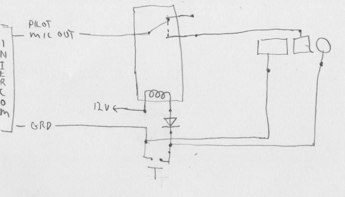
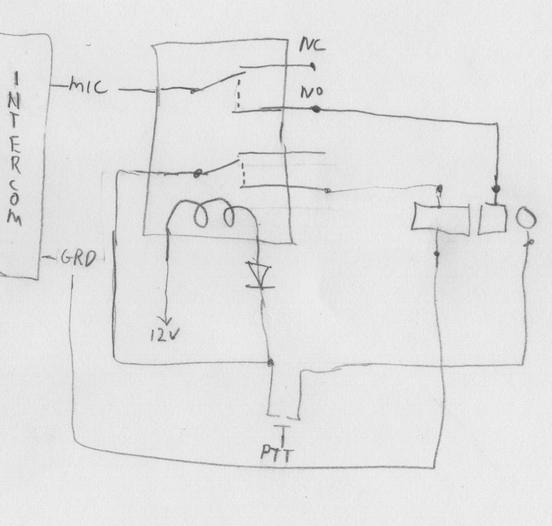
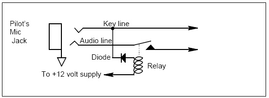
What you say makes sense about using a relay. I drew a couple diagrams, one with a single relay and another with a double relay, but I must be missing something, cuz it looks like both of them have the transmit key connected directly to ground.


I also included another RST drawing. I put a diode in the same place in my drawings, but don't know why it's needed.  I'm familiar with using a reversing diode normally put between the two coil leads, which hasn't been included. Why one and not the other?


Another nice thing about using relays in my particular case is that I've already got the spst stick switches made and fitted, just waiting for wires. If I figure this relay thing out, looks like I'll still be able to use them 
| | - The Matronics AeroElectric-List Email Forum - | | | Use the List Feature Navigator to browse the many List utilities available such as the Email Subscriptions page, Archive Search & Download, 7-Day Browse, Chat, FAQ, Photoshare, and much more:
http://www.matronics.com/Navigator?AeroElectric-List |
|
| Description: |
|
| Filesize: |
22.18 KB |
| Viewed: |
36968 Time(s) |
|
| Description: |
|
| Filesize: |
24.22 KB |
| Viewed: |
36968 Time(s) |
|
| Description: |
|
| Filesize: |
18.34 KB |
| Viewed: |
36968 Time(s) |
|
_________________
Dan |
|
| Back to top |
|
 |
user9253
Joined: 28 Mar 2008
Posts: 1927
Location: Riley TWP Michigan
|
 Posted: Fri Nov 25, 2011 8:54 pm Post subject: Re: PTT Y adapter for RST intercom Posted: Fri Nov 25, 2011 8:54 pm Post subject: Re: PTT Y adapter for RST intercom |
 |
|
Dan,

How about a circuit like this dwg attached?

Joe
| | - The Matronics AeroElectric-List Email Forum - | | | Use the List Feature Navigator to browse the many List utilities available such as the Email Subscriptions page, Archive Search & Download, 7-Day Browse, Chat, FAQ, Photoshare, and much more:
http://www.matronics.com/Navigator?AeroElectric-List |
|
| Description: |
|

Download |
| Filename: |
PTT Relays.pdf |
| Filesize: |
7.25 KB |
| Downloaded: |
671 Time(s) |
_________________
Joe Gores |
|
| Back to top |
|
 |
messydeer
Joined: 13 Feb 2006
Posts: 214
Location: Bellingham, WA
|
 Posted: Fri Nov 25, 2011 9:28 pm Post subject: Re: PTT Y adapter for RST intercom Posted: Fri Nov 25, 2011 9:28 pm Post subject: Re: PTT Y adapter for RST intercom |
 |
|
Nice


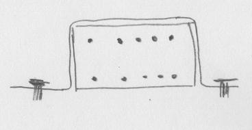
Hadn't thought about this before, but I think the PTT relay grounds would go to a/c ground, and the other 4 would go to the radio jack sleeve, right?


I also looked around Digikey.com for the relays. It was hard to match the relays with sockets that are sold separately. I'm browsing through Ebay, which may have something. I suppose I could just go without a socket and glue a strap of 032 aluminum to it. Maybe wrap it in heat shrink afterward, if gluing the case to the strap wouldn't hold up.


Also, everyone says that having two mics connected at the same time could cause problems, but I don't understand why. Does the radio power the mic? I notice that nothing has been mentioned about having the radio connected to two headphones, although I only asked Dynon about the mic. Wouldn't hooking two headphones up possibly cause some problems?
| | - The Matronics AeroElectric-List Email Forum - | | | Use the List Feature Navigator to browse the many List utilities available such as the Email Subscriptions page, Archive Search & Download, 7-Day Browse, Chat, FAQ, Photoshare, and much more:
http://www.matronics.com/Navigator?AeroElectric-List |
|
| Description: |
|
| Filesize: |
9.55 KB |
| Viewed: |
36944 Time(s) |
|
_________________
Dan |
|
| Back to top |
|
 |
user9253
Joined: 28 Mar 2008
Posts: 1927
Location: Riley TWP Michigan
|
 Posted: Sat Nov 26, 2011 7:21 am Post subject: Re: PTT Y adapter for RST intercom Posted: Sat Nov 26, 2011 7:21 am Post subject: Re: PTT Y adapter for RST intercom |
 |
|
About those diodes in the RST 442-3060 schematic. They block 12 volts from the relay coils from getting into the radio PTT circuit.
| Quote: | | Hadn't thought about this before, but I think the PTT relay grounds would go to a/c ground, and the other 4 would go to the radio jack sleeve, right? |
Sounds OK to me.
Another option besides socket mount relays are PC board mount. Digikey has many of those rated at less than 2 amps. PC type can be mounted on perf board. Radio Shack sells it. I have even seen relays taped to a wire bundle with no mounting hardware, not that I recommend doing that.
Joe
| | - The Matronics AeroElectric-List Email Forum - | | | Use the List Feature Navigator to browse the many List utilities available such as the Email Subscriptions page, Archive Search & Download, 7-Day Browse, Chat, FAQ, Photoshare, and much more:
http://www.matronics.com/Navigator?AeroElectric-List |
|
_________________
Joe Gores |
|
| Back to top |
|
 |
messydeer
Joined: 13 Feb 2006
Posts: 214
Location: Bellingham, WA
|
 Posted: Sat Nov 26, 2011 7:53 am Post subject: Re: PTT Y adapter for RST intercom Posted: Sat Nov 26, 2011 7:53 am Post subject: Re: PTT Y adapter for RST intercom |
 |
|
K.


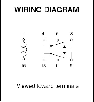
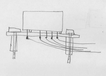
Perf board? Is that the same as breadboard? I looked at that and saw the word 'temporary' and went no further. I looked up 'perforated board' at RS, which might be different. http://www.radioshack.com/product/index.jsp?productId=2103804 I could insert the relay terminals through the holes and solder wires to them from the backside and use a couple spacer posts to keep the exposed solder off the metal panel?


I also wonder about the relay terminal wiring diagram. The attached is typical. If taken literally, if power is applied to the coil, it would move only one of the switches and not the other. No power would mean 4 contacts 6 and 13 contacts 11. With power, either 4 would go to 8, or 13 would go to 9, but not both??
| | - The Matronics AeroElectric-List Email Forum - | | | Use the List Feature Navigator to browse the many List utilities available such as the Email Subscriptions page, Archive Search & Download, 7-Day Browse, Chat, FAQ, Photoshare, and much more:
http://www.matronics.com/Navigator?AeroElectric-List |
|
| Description: |
|
| Filesize: |
17.72 KB |
| Viewed: |
36932 Time(s) |
|
| Description: |
|
| Filesize: |
15.13 KB |
| Viewed: |
36932 Time(s) |
|
_________________
Dan |
|
| Back to top |
|
 |
|
|
You cannot post new topics in this forum
You cannot reply to topics in this forum
You cannot edit your posts in this forum
You cannot delete your posts in this forum
You cannot vote in polls in this forum
You cannot attach files in this forum
You can download files in this forum
|
Powered by phpBB © 2001, 2005 phpBB Group
|


