 |
Matronics Email Lists
Web Forum Interface to the Matronics Email Lists
|
| View previous topic :: View next topic |
| Author |
Message |
ainut(at)knology.net
Guest
|
 Posted: Thu Feb 02, 2012 8:04 pm Post subject: Thermocouple leads Posted: Thu Feb 02, 2012 8:04 pm Post subject: Thermocouple leads |
 |
|
I have the book, Bob. I must say, you are Ohminous!
David M.
Robert L. Nuckolls, III wrote:
| Quote: |
<nuckolls.bob(at)aeroelectric.com>
At 06:01 PM 2/2/2012, you wrote:
>
>
> Also, any (new) junction will create an inaccuracy unless you
> calibrate with the total installation.
>
> David M.
>
A set of thermocouple leads can have quite a few
extraneous junctions without affecting accuracy
as long as (1) current in the leads is very low
indeed approaching zero. Such is the case with most
modern thermocouple instruments using specialized
integrated circuits for thermocouple signal
conditioning. And (2) EACH junction needs to be
repeated in number and kind on both sides of the
thermocouple pair.
This is described in more detail here:
http://aeroelectric.com/articles/excerpt.pdf
Bob . . .
|
--
Tell the truth. Be honest. Be responsible to and for yourself.
I liked America when it was free and it's people were responsible and had morals.
Every gram of cocaine you buy from elsewhere contributes to an innocent being murdered in Central and South America. Grow your own or Stop taking it.
| | - The Matronics AeroElectric-List Email Forum - | | | Use the List Feature Navigator to browse the many List utilities available such as the Email Subscriptions page, Archive Search & Download, 7-Day Browse, Chat, FAQ, Photoshare, and much more:
http://www.matronics.com/Navigator?AeroElectric-List |
|
|
|
| Back to top |
|
 |
ainut(at)knology.net
Guest
|
 Posted: Thu Feb 02, 2012 8:47 pm Post subject: Thermocouple leads Posted: Thu Feb 02, 2012 8:47 pm Post subject: Thermocouple leads |
 |
|
That runs contrary to my initial training (early 80's), but new things
are discovered all the time! Thanks, Paul.
David
Paul Millner wrote:
| Quote: |
Not exactly grue, David... if it's a chromel/chromel junction and a
alumel/alumel junction, there's no potential developed across it, so
nothing to calibrate out. If, for instance, someone inserts some
copper wire, you'll have chromel/copper and copper chromel junctions,
and assuming they're separated, and at different temperatures, that
temperature difference CANNOT be assumed to be constant... so there's
no way to calibrate it out.
So... either it doesn't matter, or it can't be known. No middle ground.
Paul
On 2/2/2012 4:01 PM, David wrote:
>
>
> Also, any (new) junction will create an inaccuracy unless you
> calibrate with the total installation.
>
> David M.
|
--
Tell the truth. Be honest. Be responsible to and for yourself.
I liked America when it was free and it's people were responsible and had morals.
Every gram of cocaine you buy from elsewhere contributes to an innocent being murdered in Central and South America. Grow your own or Stop taking it.
| | - The Matronics AeroElectric-List Email Forum - | | | Use the List Feature Navigator to browse the many List utilities available such as the Email Subscriptions page, Archive Search & Download, 7-Day Browse, Chat, FAQ, Photoshare, and much more:
http://www.matronics.com/Navigator?AeroElectric-List |
|
|
|
| Back to top |
|
 |
Dennis Jones
Joined: 17 Sep 2006
Posts: 45
Location: Poplar Grove, IL
|
 Posted: Thu Feb 02, 2012 8:53 pm Post subject: Re: Thermocouple leads Posted: Thu Feb 02, 2012 8:53 pm Post subject: Re: Thermocouple leads |
 |
|
It is an EPI-800 electronic system with a DPU.
| | - The Matronics AeroElectric-List Email Forum - | | | Use the List Feature Navigator to browse the many List utilities available such as the Email Subscriptions page, Archive Search & Download, 7-Day Browse, Chat, FAQ, Photoshare, and much more:
http://www.matronics.com/Navigator?AeroElectric-List |
|
|
|
| Back to top |
|
 |
millner(at)me.com
Guest
|
 Posted: Fri Feb 03, 2012 9:56 am Post subject: Thermocouple leads Posted: Fri Feb 03, 2012 9:56 am Post subject: Thermocouple leads |
 |
|
As Bob has shared, some really old systems (through, say, the 1950's)

heavily loaded the junction, so the apparent voltage was much less than

the theoretical voltage.  But, as long as those systems were calibrated,

they were repeatable and accurate.  Splicing a wire, even with J or K

wire, could increase resistance, and due to the relatively heavy current

flow, could affect the voltage and hence calibration.  And at least in

my industry, we were still using those dinosaurs into the 1980's, so ya

gotta train to work with what you have, not what's being built today.


The predominance int he industry today, though, is high impedance

devices that don't load the T/C junction... which has the side benefit

of allowing multiple devices to share a junction.  A good thing.  A

splice resistance is unimportant, as current flow is nearly nil.


Dissimilar wire, especially with junctions at dissimilar temperatures,

really plays havoc with even the open circuit voltage, and there's no

way to calibrate that out, as the temperature of those splice junctions

into the future typically can't be known.


Paul
| | - The Matronics AeroElectric-List Email Forum - | | | Use the List Feature Navigator to browse the many List utilities available such as the Email Subscriptions page, Archive Search & Download, 7-Day Browse, Chat, FAQ, Photoshare, and much more:
http://www.matronics.com/Navigator?AeroElectric-List |
|
|
|
| Back to top |
|
 |
nuckolls.bob(at)aeroelect
Guest
|
 Posted: Fri Feb 03, 2012 1:20 pm Post subject: Thermocouple leads Posted: Fri Feb 03, 2012 1:20 pm Post subject: Thermocouple leads |
 |
|
At 09:39 PM 2/2/2012, you wrote:
| Quote: |
Hmmm, Bob... the physics doesn't support your assertion, unless you
(mistakenly I'd think) assume that all those junctions are somehow
held at the same temperature. And how would you accomplish that?
|
The PAIRS have to be adjacent. For example, ordinary
gold over brass pins used to bring a t/c pair through a
connector adds negligible effect to calibration because
equal and opposite effects are inserted into each lead
and in close thermal proximity to each other and they
cancel each other out.
A tech told me of a case where he found an overheated
wire going through a connector because it was adjacent
to a non-compensated thermocouple lead . . . the other
lead in the thermocouple pair was not adjacent in the
connector housing and, therefor, was running cooler.
The warm-wire caused significant difference in temperature
reading for the afflicted pair as compared to other
t/c pairs in the same connector.
So putting 'foreign materials' into the t/c system is
not without risk . . . but easily managed with some
planning and attention to details.
| Quote: | With the relatively common high impedance measuring devices,
resistance in the leads isn't really the issue... but adding
uncontrolled junctions at different temperatures can sure play havoc
with accuracy.
|
Absolutely. For example, a silver soldered joint adds
two foreign junctions in immediate proximity. T/C-alloy
to-solder offset by a solder-to-T/C-alloy right next
to it. Two equal but opposite effects that cancel because
while not 'controlled' they are at the same temperature.
So my condition (2) was not completely explained. The
foreign junctions must be in close proximity as in the
soldered joint described above, or the t/c selector switch
box described in Figure 14-7B.
Splicing into t/c pairs to extend them will add loop
resistance. UNPOWERED temperature readout instruments
are still offered by manufacturers like ALCOR, Westach,
and others in the automotive world (see Figure 14-10C in the
'Connection). These meters must be capable of reading
thermocouple voltages directly . . . on the order
of 10 to 20 millivolts FULL SCALE. Hence they are wound
with few turns of heavier wire and draw considerable
current (like 10-50 milliamps). In these cases, the
termocouple wire tends to be heavy gauge just to get
low resistance. If you check out the range of sizes
available from Omega on type K wire:
http://www.omega.com/ppt/pptsc.asp?ref=XC_K_TC_WIRE&Nav=temh06
. . . we see everything from 14AWG to 36AWG. To be sure,
any gauge wire would work with a modern engine management
system with internally conditioned inputs. But if you
were driving an unpowered instrument over some distance
in a refinery or smelting operation, the fatter wires would
offer some options.
When unpowered gauges were used on large piston aircraft,
identical gauges and CHT/EGT thermocouples had to be individually
compensated using an external resistor so that effects
of lead length between instrument and engine could be
calibrated out.
This presupposes that the actual temperature value is of
interest. In many airplanes, one uses such an instrument
only to find "peak" on the mixture and then adjust in
25F incremental departure from peak. So whether the peak
occurs at 1/3rd scale or 3/4ths scale is not critical.
Hence, no calibration needed.
But if you've got a TIT limit to be observed, THAT system begs
for calibration. When such instruments are supplied without
provisions for exernal calibration, installation instructions
will generally include an admonition not to change the length
of the thermocouple lead.
Bob . . .
| | - The Matronics AeroElectric-List Email Forum - | | | Use the List Feature Navigator to browse the many List utilities available such as the Email Subscriptions page, Archive Search & Download, 7-Day Browse, Chat, FAQ, Photoshare, and much more:
http://www.matronics.com/Navigator?AeroElectric-List |
|
|
|
| Back to top |
|
 |
steve(at)tomasara.com
Guest
|
 Posted: Sat Feb 04, 2012 5:21 am Post subject: Thermocouple leads Posted: Sat Feb 04, 2012 5:21 am Post subject: Thermocouple leads |
 |
|
Group,


Although it's made clear enough in the book, I don't think it's come

through clear enough yet in this thread that when using dissimilar

junctions you ALSO have to worry that you don't inadvertently move the

reference (i.e. "cold") junction(s).


As an illustration, my Long-EZ, when received, had a short pigtail on

the under-sparkplug CHT T-couple.  It was transitioned to copper pretty

much adjacent to the neighboring cylinder.  The copper ran all the way

to a powered (i.e. high impedance) Westach gauge.  The Westach is

designed (best I can tell) so that the cold junction(s) (i.e. the final

terminations to non-T-couple wire) are actually made by the junctions

that result from the crimps between what is supposed to be T-couple wire

and fast-on connectors right at the back of the gauge.  This allows a

temp sensor in the gauge to compensate for the voltages at the cold

junctions.


By running copper from the T-couple wire pig-tails all the way to the

gauge, there would usually be a significant temperature difference

between the actual cold junctions (next to a cylinder) and the intended

cold junctions (behind the panel) which would show up directly in error

on the reading of the gauge.  That's all fixed now...


Steve Stearns

Boulder/Longmont, Colorado

CSA,EAA,IAC,AOPA,PE,ARRL,BARC (but ignorant none-the-less)

Restoring (since 1/07) and flying again (8/11!): N45FC O235 Longeze

Cothern/Friling CF1 (~1000 Hrs)

Flying (since 9/86): N43732 A65 Taylorcraft BC12D
| | - The Matronics AeroElectric-List Email Forum - | | | Use the List Feature Navigator to browse the many List utilities available such as the Email Subscriptions page, Archive Search & Download, 7-Day Browse, Chat, FAQ, Photoshare, and much more:
http://www.matronics.com/Navigator?AeroElectric-List |
|
|
|
| Back to top |
|
 |
nuckolls.bob(at)aeroelect
Guest
|
 Posted: Sat Feb 04, 2012 7:43 am Post subject: Thermocouple leads Posted: Sat Feb 04, 2012 7:43 am Post subject: Thermocouple leads |
 |
|
At 07:15 AM 2/4/2012, you wrote:

 --> AeroElectric-List message posted by: Steve Stearns <steve(at)tomasara.com>


 Group,


 Although it's made clear enough in the book, I don't think it's come through clear enough yet in this thread that when using dissimilar junctions you ALSO have to worry that you don't inadvertently move the reference (i.e. "cold") junction(s).


 As an illustration, my Long-EZ, when received, had a short pigtail on the under-sparkplug CHT T-couple.  It was transitioned to copper pretty much adjacent to the neighboring cylinder.  The copper ran all the way to a powered (i.e. high impedance) Westach gauge.  The Westach is designed (best I can tell) so that the cold junction(s) (i.e. the final terminations to non-T-couple wire) are actually made by the junctions that result from the crimps between what is supposed to be T-couple wire and fast-on connectors right at the back of the gauge.  This allows a temp sensor in the gauge to compensate for the voltages at the cold junctions.


 By running copper from the T-couple wire pig-tails all the way to the gauge, there would usually be a significant temperature difference between the actual cold junctions (next to a cylinder) and the intended cold junctions (behind the panel) which would show up directly in error on the reading of the gauge.  That's all fixed now...


   Exactly. I've often thought that we should perhaps

   forsake the term "cold junction" for "reference junction".

   Classically, the reference junction was any point in the

   system where the transition from thermocouple alloys

   and instrumentation was known with accuracy. It could

   be hotter or colder than the temperature of interest.

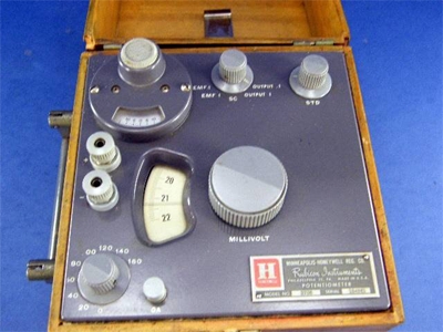
   I recall the first thermocouple array I ever saw installed on

   a flight test airplane at Cessna. The reference junction

   for perhaps a dozen switched thermocouples was submerged

   in a Thermos bottle filled with crushed ice made with

   distilled water. Pretty durn close to 0 degrees C.


   But the self powered instruments couldn't be fitted with

   ice baths so an alternative reference junction compensation

   scheme had to be crafted. I've been meaning to dig through

   the old patents someday and see what the popular techniques

   were 70 years ago. In that test setup, a flight test technician

   had to measure each thermocouple one at a time using a precision

   potentiometer bridge in his lap. The millivolt readings were

   written to a test data sheet and converted to temperatures

   later when he wrote his test report.


   Tedious . . .


 [img]cid:.0[/img]


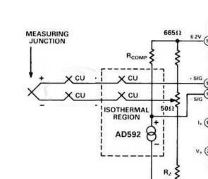
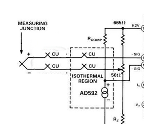
   A modern incarnation for implementing a reference junction

   is illustrated here:


 [img]cid:.0[/img]


   I think this is out of an analog devices AppNote illustrating how

   an AD592 temperature sensor is situated in thermal proximity to a T/C-to-Copper

   reference junction. Thus, while the "reference" can be wandering around

   with ambient temperature, it's effect on output is known and

   compensated for. Even this technique is outdated since Analog Devices

   and others have created thermocouple conditioner chips that feature

   built in reference junction sensing features and offer user friendly

   10 mv/degree output signals.


   The situation in your airplane as-received could be illustrated

   like this:


 [img]cid:.1[/img]


    The indiscriminate insertion of a "rogue" junction added new but

    unknown effects that the instrument would not be able to resolve

    resulting in wildly inaccurate readings.


   Bob . . .
| | - The Matronics AeroElectric-List Email Forum - | | | Use the List Feature Navigator to browse the many List utilities available such as the Email Subscriptions page, Archive Search & Download, 7-Day Browse, Chat, FAQ, Photoshare, and much more:
http://www.matronics.com/Navigator?AeroElectric-List |
|
| Description: |
|
| Filesize: |
97.75 KB |
| Viewed: |
7842 Time(s) |
|
| Description: |
|
| Filesize: |
32.01 KB |
| Viewed: |
7842 Time(s) |
|
|
|
| Back to top |
|
 |
nuckolls.bob(at)aeroelect
Guest
|
 Posted: Sat Feb 04, 2012 8:11 am Post subject: Thermocouple leads Posted: Sat Feb 04, 2012 8:11 am Post subject: Thermocouple leads |
 |
|
At 03:53 AM 2/2/2012, you wrote:

Another "lightbulb" reply, thank you. I know I've

read this in the Connection, but still, a reminder doesn't go amiss.


Is this effect mitigated by having a common

ground on the firewall, with a braided strap to

the engine? Â If the instruments are grounded to

the forest of tabs, and that's only a short

distance along a fat piece of copper to the engine...


    Yes. If you're using a forest of tabs firewall

    ground and have the fat braid to the crankcase,

    I'd be surprised if you have a ground loop issue

    with the thermocouples.

At 01:20 PM 2/1/2012, you wrote:


I'll second that. On the Dynon an improper ground

on 1 device/sensor can/will impact the reading on

another. I used to have an old Cadillac which

when you moved the electric seat the high beams

flashed. They called it a feature.


    Hmmmm . . . how do you mean "improper ground" on a

    sensor? Are we talking thermocouples here? In the

    case of a thermocouple welded down to it's thermowell,

    the installer has no control over the existence or

    quality of that ground.


    When considering devices like temperature or pressure

    sensors, if they're fitted with ground wires, then

    that wire should be brought back to the point where

    the instrument grounds . . . either the forest of

    tabs on the firewall or the instrument panel ground.


    If the sensor gets grounded by virtue of it's being

    attached to the engine (common with automotive devices)

    then again, the installer has little control over

    any voltage differentials that the the sensor ground

    verus the instrument ground . . . except to bring

    the two a close together as possible (forest of tabs)

    and use a fat bonding jumper.


    If improper delivery of signal to one channel of

    the instrument can upset readings of other channels,

    then the instrument at least suspected of poor

    design. I'd find that hard to believe of Dynon.

   Bob . . .
| | - The Matronics AeroElectric-List Email Forum - | | | Use the List Feature Navigator to browse the many List utilities available such as the Email Subscriptions page, Archive Search & Download, 7-Day Browse, Chat, FAQ, Photoshare, and much more:
http://www.matronics.com/Navigator?AeroElectric-List |
|
|
|
| Back to top |
|
 |
nuckolls.bob(at)aeroelect
Guest
|
 Posted: Sat Feb 04, 2012 8:13 am Post subject: Thermocouple leads Posted: Sat Feb 04, 2012 8:13 am Post subject: Thermocouple leads |
 |
|
The second image got hosed during a cut-n-paste. Here's

 how the message SHOULD have looked.  -BN-

 -


 At 07:15 AM 2/4/2012, you wrote:

 --> AeroElectric-List message posted by: Steve Stearns <steve(at)tomasara.com>


 Group,


 Although it's made clear enough in the book, I don't think it's come through clear enough yet in this thread that when using dissimilar junctions you ALSO have to worry that you don't inadvertently move the reference (i.e. "cold") junction(s).


 As an illustration, my Long-EZ, when received, had a short pigtail on the under-sparkplug CHT T-couple.  It was transitioned to copper pretty much adjacent to the neighboring cylinder.  The copper ran all the way to a powered (i.e. high impedance) Westach gauge.  The Westach is designed (best I can tell) so that the cold junction(s) (i.e. the final terminations to non-T-couple wire) are actually made by the junctions that result from the crimps between what is supposed to be T-couple wire and fast-on connectors right at the back of the gauge.  This allows a temp sensor in the gauge to compensate for the voltages at the cold junctions.


 By running copper from the T-couple wire pig-tails all the way to the gauge, there would usually be a significant temperature difference between the actual cold junctions (next to a cylinder) and the intended cold junctions (behind the panel) which would show up directly in error on the reading of the gauge.  That's all fixed now...


   Exactly. I've often thought that we should perhaps

   forsake the term "cold junction" for "reference junction".

   Classically, the reference junction was any point in the

   system where the transition from thermocouple alloys

   and instrumentation was known with accuracy. It could

   be hotter or colder than the temperature of interest.

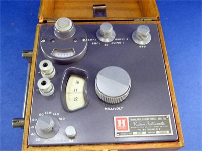
   I recall the first thermocouple array I ever saw installed on

   a flight test airplane at Cessna. The reference junction

   for perhaps a dozen switched thermocouples was submerged

   in a Thermos bottle filled with crushed ice made with

   distilled water. Pretty durn close to 0 degrees C.


   But the self powered instruments couldn't be fitted with

   ice baths so an alternative reference junction compensation

   scheme had to be crafted. I've been meaning to dig through

   the old patents someday and see what the popular techniques

   were 70 years ago. In that test setup, a flight test technician

   had to measure each thermocouple one at a time using a precision

   potentiometer bridge in his lap. The millivolt readings were

   written to a test data sheet and converted to temperatures

   later when he wrote his test report.


   Tedious . . .


 [img]cid:7.1.0.9.0.20120204100504.01e3b368(at)aeroelectric.com.2[/img]


   A modern incarnation for implementing a reference junction

   is illustrated here:


 [img]cid:7.1.0.9.0.20120204100504.01e3b368(at)aeroelectric.com.3[/img]


   I think this is out of an analog devices AppNote illustrating how

   an AD592 temperature sensor is situated in thermal proximity to a T/C-to-Copper

   reference junction. Thus, while the "reference" can be wandering around

   with ambient temperature, it's effect on output is known and

   compensated for. Even this technique is outdated since Analog Devices

   and others have created thermocouple conditioner chips that feature

   built in reference junction sensing features and offer user friendly

   10 mv/degree output signals.


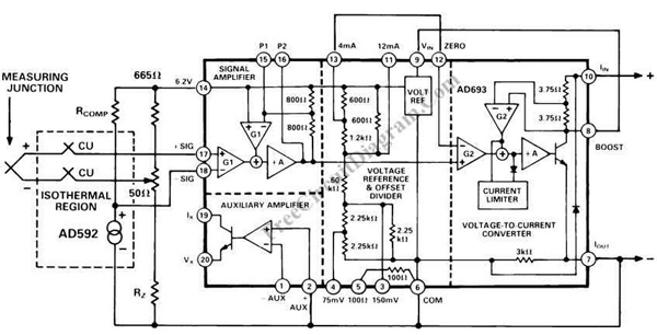
   The situation in your airplane as-received could be illustrated

   like this:


 [img]cid:7.1.0.9.0.20120204100504.01e3b368(at)aeroelectric.com.4[/img]


    The indiscriminate insertion of a "rogue" junction added new but

    unknown effects that the instrument would not be able to resolve

    resulting in wildly inaccurate readings.


   Bob . . .
| | - The Matronics AeroElectric-List Email Forum - | | | Use the List Feature Navigator to browse the many List utilities available such as the Email Subscriptions page, Archive Search & Download, 7-Day Browse, Chat, FAQ, Photoshare, and much more:
http://www.matronics.com/Navigator?AeroElectric-List |
|
| Description: |
|
| Filesize: |
97.75 KB |
| Viewed: |
7841 Time(s) |
|
| Description: |
|
| Filesize: |
112.22 KB |
| Viewed: |
7841 Time(s) |
|
| Description: |
|
| Filesize: |
32.01 KB |
| Viewed: |
7841 Time(s) |
|
|
|
| Back to top |
|
 |
ainut(at)knology.net
Guest
|
 Posted: Sat Feb 04, 2012 12:21 pm Post subject: Thermocouple leads Posted: Sat Feb 04, 2012 12:21 pm Post subject: Thermocouple leads |
 |
|
Bob, I'm using the AD594/595 and it is my understanding that even with
all the magic inside the chip, one has to compensate for the extra cold
junctions aka reference junctions.
David
Robert L. Nuckolls, III wrote:
| Quote: | At 07:15 AM 2/4/2012, you wrote:
<steve(at)tomasara.com>
Group,
Although it's made clear enough in the book, I don't think it's come
through clear enough yet in this thread that when using dissimilar
junctions you ALSO have to worry that you don't inadvertently move the
reference (i.e. "cold") junction(s).
As an illustration, my Long-EZ, when received, had a short pigtail on
the under-sparkplug CHT T-couple. It was transitioned to copper
pretty much adjacent to the neighboring cylinder. The copper ran all
the way to a powered (i.e. high impedance) Westach gauge. The Westach
is designed (best I can tell) so that the cold junction(s) (i.e. the
final terminations to non-T-couple wire) are actually made by the
junctions that result from the crimps between what is supposed to be
T-couple wire and fast-on connectors right at the back of the gauge.
This allows a temp sensor in the gauge to compensate for the voltages
at the cold junctions.
By running copper from the T-couple wire pig-tails all the way to the
gauge, there would usually be a significant temperature difference
between the actual cold junctions (next to a cylinder) and the
intended cold junctions (behind the panel) which would show up
directly in error on the reading of the gauge. That's all fixed now...
Exactly. I've often thought that we should perhaps
forsake the term "cold junction" for "reference junction".
Classically, the reference junction was any point in the
system where the transition from thermocouple alloys
and instrumentation was known with accuracy. It could
be hotter or colder than the temperature of interest.
I recall the first thermocouple array I ever saw installed on
a flight test airplane at Cessna. The reference junction
for perhaps a dozen switched thermocouples was submerged
in a Thermos bottle filled with crushed ice made with
distilled water. Pretty durn close to 0 degrees C.
But the self powered instruments couldn't be fitted with
ice baths so an alternative reference junction compensation
scheme had to be crafted. I've been meaning to dig through
the old patents someday and see what the popular techniques
were 70 years ago. In that test setup, a flight test technician
had to measure each thermocouple one at a time using a precision
potentiometer bridge in his lap. The millivolt readings were
written to a test data sheet and converted to temperatures
later when he wrote his test report.
Tedious . . .
Emacs!
A modern incarnation for implementing a reference junction
is illustrated here:
Emacs!
I think this is out of an analog devices AppNote illustrating how
an AD592 temperature sensor is situated in thermal proximity to a
T/C-to-Copper
reference junction. Thus, while the "reference" can be wandering around
with ambient temperature, it's effect on output is known and
compensated for. Even this technique is outdated since Analog Devices
and others have created thermocouple conditioner chips that feature
built in reference junction sensing features and offer user friendly
10 mv/degree output signals.
The situation in your airplane as-received could be illustrated
like this:
Emacs!
The indiscriminate insertion of a "rogue" junction added new but
unknown effects that the instrument would not be able to resolve
resulting in wildly inaccurate readings.
Bob . . .
|
--
Tell the truth. Be honest. Be responsible to and for yourself.
We want our freedoms back. Strike the illegal legislations called: 1) obamacare, 2) "Patriot (HA!) Act", and 3) 'presidential orders' that affect anyone besides gubmnt worker bees.
Hate crime laws? Really? Thought police? Orwell would be proud.
Every gram of cocaine you buy from elsewhere contributes to an innocent being murdered in Central and South America. Grow your own or Stop taking it.
| | - The Matronics AeroElectric-List Email Forum - | | | Use the List Feature Navigator to browse the many List utilities available such as the Email Subscriptions page, Archive Search & Download, 7-Day Browse, Chat, FAQ, Photoshare, and much more:
http://www.matronics.com/Navigator?AeroElectric-List |
|
|
|
| Back to top |
|
 |
nuckolls.bob(at)aeroelect
Guest
|
 Posted: Sat Feb 04, 2012 4:54 pm Post subject: Thermocouple leads Posted: Sat Feb 04, 2012 4:54 pm Post subject: Thermocouple leads |
 |
|
At 01:48 PM 2/4/2012, you wrote:
| Quote: | --> AeroElectric-List message posted by: David <ainut(at)knology.net>
Bob, I'm using the AD594/595 and it is my understanding that even with all the magic inside the chip, one has to compensate for the extra cold junctions aka reference junctions. |
No. See
http://tinyurl.com/6xp4xc
In the features list right on the front cover we see
the statement "Built-In Ice Point Compensation".
In Figure 13 we see an interesting use of the 594/595
as a Celsius thermometer. Just short the t/c pins together
and the chip reports it's own internal temperature (very
close to ambient).
In the data acquisition signal conditioner I illustrated
at:
http://aeroelectric.com/Pictures/Data_Acquisition/Weeder_Module_DAS_4.jpg
. . . one of those thermocouple conditioner chips was used
for just that purpose. This gizmo was installed in the nose
of a Beechjet for some pitot temperature studies at high
altitude. Some of the integrated circuits were qualified
down only to 0 degrees C. If you look at the picture
you can see a power resistor peeking out from under the
perf-board. That resistor and three others were used as
heaters controlled by one of the T/C chips to maintain
10C inside the box.
So, I'm happy to report that these critters are very complete
and require no ice-point reference junctions.
Bob . . . [quote][b]
| | - The Matronics AeroElectric-List Email Forum - | | | Use the List Feature Navigator to browse the many List utilities available such as the Email Subscriptions page, Archive Search & Download, 7-Day Browse, Chat, FAQ, Photoshare, and much more:
http://www.matronics.com/Navigator?AeroElectric-List |
|
|
|
| Back to top |
|
 |
natsuto
Guest
|
 Posted: Tue Feb 14, 2012 5:33 pm Post subject: Re: Thermocouple leads Posted: Tue Feb 14, 2012 5:33 pm Post subject: Re: Thermocouple leads |
 |
|
I have seen improper ground, cause all to read. Engine to ensure that the equipment grounding, rather than the ground bus.
| | - The Matronics AeroElectric-List Email Forum - | | | Use the List Feature Navigator to browse the many List utilities available such as the Email Subscriptions page, Archive Search & Download, 7-Day Browse, Chat, FAQ, Photoshare, and much more:
http://www.matronics.com/Navigator?AeroElectric-List |
|
|
|
| Back to top |
|
 |
|
|
You cannot post new topics in this forum
You cannot reply to topics in this forum
You cannot edit your posts in this forum
You cannot delete your posts in this forum
You cannot vote in polls in this forum
You cannot attach files in this forum
You can download files in this forum
|
Powered by phpBB © 2001, 2005 phpBB Group
|


