 |
Matronics Email Lists
Web Forum Interface to the Matronics Email Lists
|
| View previous topic :: View next topic |
| Author |
Message |
fedico94(at)mchsi.com
Guest
|
 Posted: Thu Jun 14, 2012 2:48 pm Post subject: G3X Garmin EFIS Posted: Thu Jun 14, 2012 2:48 pm Post subject: G3X Garmin EFIS |
 |
|
need advice

I want to test the hall effect sensor wire input to the G3X (Slick Mag sensor from UMA).  I have never gotten the rpm sensor to test as one would a cam shaft hall effect sensor on a car with an analogue voltmeter.    According to Klaus Savier's instructions the input signal from his device will record on the G3X

His signal from the Plasma II puts out a square wave (rather than sine wave) at 10V amplitude and

0.3me ? width.  2 pulses per revolution so about so for 2k rpm need 4K pulses per min.

Is there a reasonably priced pulse generator that will send out a signal like this or is there place to get it locally like radio shack ?


The flap indicator does not work.  it is dependent upon a slde potentiometer from Ray Allen

Is there a way to build a device to send a signal down the input wire to the G3X that varies voltage ? The G3X displays 0.3 V on the flap panel but no chage as I run the flaps up and down. I assume the max voltage going in is 0.3V.  I thought of using a 9 V battery with a potentiometer and this may be useful for the fuel senders as well.


I have yet to test the fuel tank senders to see if they work.  Very disappointed that this professionally assembled suite of Garmin equipment has some major problems in receiving a signal.

Hard to tell if it is the senders or the LSU computer brain.  So far the senders all check out as working properly.  My main problem is getting access to data to safely test the input signal wires for the RPM sensor, but Klaus Savier has some information on his Plasma II device for electronic signal to the input of the RPM of the G3X.  Prior to installation I use OHM meter to make sure the supplied harneses had continuity and correct pin readout.  So much for plug-n-play.
| | - The Matronics AeroElectric-List Email Forum - | | | Use the List Feature Navigator to browse the many List utilities available such as the Email Subscriptions page, Archive Search & Download, 7-Day Browse, Chat, FAQ, Photoshare, and much more:
http://www.matronics.com/Navigator?AeroElectric-List |
|
|
|
| Back to top |
|
 |
nuckolls.bob(at)aeroelect
Guest
|
| Posted: Fri Jun 15, 2012 6:41 am Post subject: G3X Garmin EFIS |
|
|
At 05:45 PM 6/14/2012, you wrote:
--> AeroElectric-List message posted by: fedico94(at)mchsi.com
need advice
I want to test the hall effect sensor wire input to the G3X (Slick Mag sensor from UMA). I have never gotten the rpm sensor to test as one would a cam shaft hall effect sensor on a car with an analogue voltmeter.
Sensors that can be 'read' with an analog
voltmeter are generally variable reluctance
devices . . .

These have a permanent magnet center pole piece with
many turns of 'cat hair' wound around them. When the
teeth of a ferrous gear fly past the end of the pole
piece, the change in magnetic flux around the wires
generates a small, generally sinusoidal, ac waveform
with a frequency equal to teeth-per-second and an
amplitude proportional to teeth-per-second.
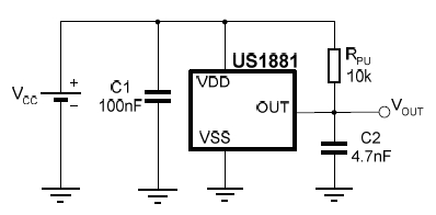
On the other hand, a 'hall effect device' for RPM
sensing generally depends on an external magnetic
field (like the one that spins around the shaft of
a magneto). It's usually a 3-wire device (ground,
signal and power) but CAN be a 2-wire device for
accommodating instruments. These need to be powered
up by 3-15 volts DC and the output signal is generally
a square wave, again frequency equal to pole passages
per second but an amplitude fixed to some value close
to the power supply voltage.
[img]cid:.0[/img]
So if the sensor you're trying to test is indeed a Hall
Effect device, you'll need to wire it up to emulate the
power supply and signal loads present in normal operations.
Observation of a the output signal will require an
oscilloscope as opposed to a simple voltmeter.
According to Klaus Savier's instructions the input signal from his device will record on the G3X
His signal from the Plasma II puts out a square wave (rather than sine wave) at 10V amplitude and
0.3me ? width. 2 pulses per revolution so about so for 2k rpm need 4K pulses per min.
Is there a reasonably priced pulse generator that will send out a signal like this or is there place to get it locally like radio shack ?
Sure, it's called a 555 timer.
The flap indicator does not work. it is dependent upon a slde potentiometer from Ray Allen
Is there a way to build a device to send a signal down the input wire to the G3X that varies voltage ? The G3X displays 0.3 V on the flap panel but no chage as I run the flaps up and down. I assume the max voltage going in is 0.3V. I thought of using a 9 V battery with a potentiometer and this may be useful for the fuel senders as well.
That seems likely.
I have yet to test the fuel tank senders to see if they work. Very disappointed that this professionally assembled suite of Garmin equipment has some major problems in receiving a signal.
Hard to tell if it is the senders or the LSU computer brain. So far the senders all check out as working properly. My main problem is getting access to data to safely test the input signal wires for the RPM sensor, but Klaus Savier has some information on his Plasma II device for electronic signal to the input of the RPM of the G3X. Prior to installation I use OHM meter to make sure the supplied harneses had continuity and correct pin readout. So much for plug-n-play.
Garmin is pretty good at displaying the right
numbers representing various system values. The
problem is with the wide variety of sensor styles,
scale factors, offsets and wave shapes. Had Garmin
supplied all components they would have been married
in production. But as you've discovered, doing the
engagement, marriage and honeymoon yourself can
be challenging.
These have a permanent magnet center pole piece with
many turns of 'cat hair' wound around them. When the
teeth of a ferrous gear fly past the end of the pole
piece, the change in magnetic flux around the wires
generates a small, generally sinusoidal, ac waveform
with a frequency equal to teeth-per-second and an
amplitude proportional to teeth-per-second.
On the other hand, a 'hall effect device' for RPM
sensing generally depends on an external magnetic
field (like the one that spins around the shaft of
a magneto). It's usually a 3-wire device (ground,
signal and power) but CAN be a 2-wire device for
accommodating instruments. These need to be powered
up by 3-15 volts DC and the output signal is generally
a square wave, again frequency equal to pole passages
per second but an amplitude fixed to some value close
to the power supply voltage.
So if the sensor you're trying to test is indeed a Hall
Effect device, you'll need to wire it up to emulate the
power supply and signal loads present in normal operations.
Observation of a the output signal will require an
oscilloscope as opposed to a simple voltmeter.
| Quote: | According to Klaus Savier's instructions the input signal from his device will record on the G3X
His signal from the Plasma II puts out a square wave (rather than sine wave) at 10V amplitude and
0.3me ? width. 2 pulses per revolution so about so for 2k rpm need 4K pulses per min.Is there a reasonably priced pulse generator that will send out a signal like this or is there place to get it locally like radio shack ? |
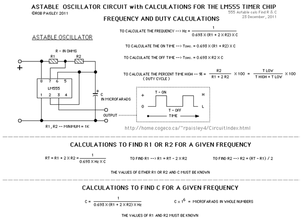
Sure, it's called a 555 timer. See schematic
[img]cid:.1[/img]
According to the calculator just below this image at
http://home.cogeco.ca/~rpaisley4/LM555Astable.GIF
100 ohms at R1, 3300 ohms at R2, 4.7 uF at
C1 will give you about 45 Hz, 2700 pulses
per minute or 1350 rpm equivalent test signal.
Running this test generator on a 9v battery
would probably be close enough to the 10v pulse
generated by the Lightspeed system.
The flap indicator does not work. it is dependent upon a slde potentiometer from Ray Allen
Is there a way to build a device to send a signal down the input wire to the G3X that varies voltage ? The G3X displays 0.3 V on the flap panel but no chage as I run the flaps up and down. I assume the max voltage going in is 0.3V. I thought of using a 9 V battery with a potentiometer and this may be useful for the fuel senders as well.
That seems likely.
I have yet to test the fuel tank senders to see if they work. Very disappointed that this professionally assembled suite of Garmin equipment has some major problems in receiving a signal.
Hard to tell if it is the senders or the LSU computer brain. So far the senders all check out as working properly. My main problem is getting access to data to safely test the input signal wires for the RPM sensor, but Klaus Savier has some information on his Plasma II device for electronic signal to the input of the RPM of the G3X. Prior to installation I use OHM meter to make sure the supplied harneses had continuity and correct pin readout. So much for plug-n-play.
Garmin is pretty good at displaying the right
numbers representing various system values. The
problem is with the wide variety of sensor styles,
scale factors, offsets and wave shapes. Had Garmin
supplied all components they would have been married
in production. But as you've discovered, doing the
engagement, marriage and honeymoon yourself can
be challenging.
Bob . . .
| | - The Matronics AeroElectric-List Email Forum - | | | Use the List Feature Navigator to browse the many List utilities available such as the Email Subscriptions page, Archive Search & Download, 7-Day Browse, Chat, FAQ, Photoshare, and much more:
http://www.matronics.com/Navigator?AeroElectric-List |
|
| Description: |
|
| Filesize: |
21.47 KB |
| Viewed: |
1552 Time(s) |
|
| Description: |
|
| Filesize: |
109.98 KB |
| Viewed: |
1552 Time(s) |
|
|
|
| Back to top |
|
|
fedico94(at)mchsi.com
Guest
|
| Posted: Fri Jun 15, 2012 5:54 pm Post subject: G3X Garmin EFIS |
|
|
thanks for your timely and accurate advice.  I researched the internet last night and it seems a number of schools use the 555 timer circuits.  Your calculations and drawing will make my my breadboard assembly easy.  Unfortunately I found major wiring snafu in G3X system.  The signal input wire does trace to the appropriate pin 17 of the 80 pin J732 LSU connector.  Unfortunately I get a voltmeter reading of 13.5 out of this wire.  The power should come form pin 58 wire but has no power coming out.  It seems this system is to complex to assemble, even for a large avionics shop in northern US.

---
| | - The Matronics AeroElectric-List Email Forum - | | | Use the List Feature Navigator to browse the many List utilities available such as the Email Subscriptions page, Archive Search & Download, 7-Day Browse, Chat, FAQ, Photoshare, and much more:
http://www.matronics.com/Navigator?AeroElectric-List |
|
|
|
| Back to top |
|
|
|
|
You cannot post new topics in this forum
You cannot reply to topics in this forum
You cannot edit your posts in this forum
You cannot delete your posts in this forum
You cannot vote in polls in this forum
You cannot attach files in this forum
You can download files in this forum
|
Powered by phpBB © 2001, 2005 phpBB Group
|

