 |
Matronics Email Lists
Web Forum Interface to the Matronics Email Lists
|
| View previous topic :: View next topic |
| Author |
Message |
trigo(at)mail.telepac.pt
Guest
|
 Posted: Fri Nov 01, 2013 6:20 am Post subject: Watts on resistors Posted: Fri Nov 01, 2013 6:20 am Post subject: Watts on resistors |
 |
|
Bob and all


The VP-X Pro installation manual recomends, in order to have Volt indication from the Aux Batt, to connect the + terminal to a certain pin in the box, trough a 1Kohm - 1W resistor.

Problem is that I can only find 1Kohm - 2W resistor. So, to learn something else today, can someone please explain if there is any problem if I use the 2W instead of 1W resistor.

(Please don't answer indicating a source for 1W resistors...)


Regards

Carlos
| | - The Matronics AeroElectric-List Email Forum - | | | Use the List Feature Navigator to browse the many List utilities available such as the Email Subscriptions page, Archive Search & Download, 7-Day Browse, Chat, FAQ, Photoshare, and much more:
http://www.matronics.com/Navigator?AeroElectric-List |
|
|
|
| Back to top |
|
 |
mrspudandcompany(at)veriz
Guest
|
 Posted: Fri Nov 01, 2013 7:16 am Post subject: Watts on resistors Posted: Fri Nov 01, 2013 7:16 am Post subject: Watts on resistors |
 |
|
| Quote: | Problem is that I can only find 1Kohm - 2W resistor. So, to learn
something else today, can someone please explain if there is any problem
if I use the 2W instead of 1W resistor.
|
The 2 watt resistor will work exactly the same in the circuit as a 1
watt.
The only difference is that the 2 watt is somewhat larger with more
surface
area and can dissipate more heat without burning up.
Roger
--
Do you have a slow PC? Try a Free scan http://www.spamfighter.com/SLOW-PCfighter?cid=sigen
| | - The Matronics AeroElectric-List Email Forum - | | | Use the List Feature Navigator to browse the many List utilities available such as the Email Subscriptions page, Archive Search & Download, 7-Day Browse, Chat, FAQ, Photoshare, and much more:
http://www.matronics.com/Navigator?AeroElectric-List |
|
|
|
| Back to top |
|
 |
henador_titzoff(at)yahoo.
Guest
|
 Posted: Fri Nov 01, 2013 7:33 am Post subject: Watts on resistors Posted: Fri Nov 01, 2013 7:33 am Post subject: Watts on resistors |
 |
|
It should be no problem, Carlos, as long as you have enough room and the circuit isn't frequency sensitive.  Wattage is the resistor's ability to dissipate heat, and the resistor is bigger as the wattage goes up.


Henador Titzoff


--------------------------------------------

On Fri, 11/1/13, Carlos Trigo <trigo(at)mail.telepac.pt> wrote:


 Subject: Watts on resistors

 To: "aeroelectric-list(at)matronics.com" <aeroelectric-list(at)matronics.com>

 Date: Friday, November 1, 2013, 7:21 AM


 --> AeroElectric-List message

 posted by: Carlos Trigo <trigo(at)mail.telepac.pt>


 Bob and all


 The VP-X Pro installation manual recomends, in order to have

 Volt indication from the Aux Batt, to connect the + terminal

 to a certain pin in the box, trough a 1Kohm - 1W resistor.

 Problem is that I can only find 1Kohm - 2W resistor. So, to

 learn something else today, can someone please explain if

 there is any problem if I use the 2W instead of 1W

 resistor.

 (Please don't answer indicating a source for 1W

 resistors...)


 Regards

 Carlos


 Lists This Month --

 Some AWESOME FREE Gifts!)

 Raiser.  Click on

 more about

 Gifts provided

 www.aeroelectric.com

 www.buildersbooks.com

 www.homebuilthelp.com

 www.mypilotstore.com

 www.mrrace.com

               -Matt

 Dralle, List Admin.

 AeroElectric-List Email Forum -

    - MATRONICS WEB FORUMS -
| | - The Matronics AeroElectric-List Email Forum - | | | Use the List Feature Navigator to browse the many List utilities available such as the Email Subscriptions page, Archive Search & Download, 7-Day Browse, Chat, FAQ, Photoshare, and much more:
http://www.matronics.com/Navigator?AeroElectric-List |
|
|
|
| Back to top |
|
 |
nuckolls.bob(at)aeroelect
Guest
|
 Posted: Fri Nov 01, 2013 7:40 am Post subject: Watts on resistors Posted: Fri Nov 01, 2013 7:40 am Post subject: Watts on resistors |
 |
|
At 09:21 AM 11/1/2013, you wrote:
| Quote: | --> AeroElectric-List message posted by: Carlos Trigo <trigo(at)mail.telepac.pt>
Bob and all
The VP-X Pro installation manual recomends, in order to have Volt indication from the Aux Batt, to connect the + terminal to a certain pin in the box, trough a 1Kohm - 1W resistor.
Problem is that I can only find 1Kohm - 2W resistor. So, to learn something else today, can someone please explain if there is any problem if I use the 2W instead of 1W resistor.
(Please don't answer indicating a source for 1W resistors...)
|
That's an easy one.
The resistor is a substitute for a fuse. Further,
it's called out as 1-watt for mechanical convenience
and robustness. Examples:
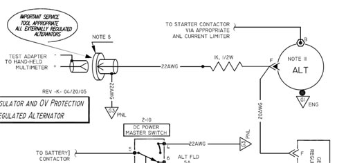
Some years back I suggested that the most valuable
and often least accessible data point for diagnosing
an alternator problem is to watch FIELD VOLTAGE
behavior while putting an alternator through
its paces.
I published this little feature in Z-23 suggesting
a permanently attached wire PROTECTED by a resistor
leading from the alternator field to some handy point
in the cockpit.
[img]cid:.0[/img]
A fuse would be okay too. A 1/4 watt would work but 1/2
watt was mechanically more robust, 1w would have
been better yet. So as long as you don't mind a larger
'lump' in your battery sense lead, a 2W resistor is
okay as well.
http://tinyurl.com/kyc6tq6
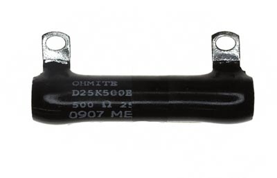
I think it was here on the List that I once suggested
a tubular, 10-watt wire wound resistor with flag
terminals as a suitable enclosure for a reed switch
current sensor.
[img]cid:.1[/img]
The 'jeep' was to put lead wires on the reed switch
then epoxy into place down the center of the tubular
resistor. Then wind an excitation coil around the
center of the resistor over the reed. Calibrate
closure current for the reed by adjusting coil
turns.
In this case, the actual value of the resistor
wasn't critical . . . just needed to be high
enough not to adversely affect current through
the the coil. The resistor became a robust
'housing' for the current sense relay offering
a convenient terminals to tie off ends
of the coil.
These are but two examples of many where the
designer's 'sizing' of a component may not
have obvious foundation in the original
design goals for the part.
Bob . . .
| | - The Matronics AeroElectric-List Email Forum - | | | Use the List Feature Navigator to browse the many List utilities available such as the Email Subscriptions page, Archive Search & Download, 7-Day Browse, Chat, FAQ, Photoshare, and much more:
http://www.matronics.com/Navigator?AeroElectric-List |
|
| Description: |
|
| Filesize: |
42.18 KB |
| Viewed: |
1989 Time(s) |

|
| Description: |
|
| Filesize: |
18.48 KB |
| Viewed: |
1989 Time(s) |

|
|
|
| Back to top |
|
 |
nuckolls.bob(at)aeroelect
Guest
|
 Posted: Fri Nov 01, 2013 7:42 am Post subject: Watts on resistors Posted: Fri Nov 01, 2013 7:42 am Post subject: Watts on resistors |
 |
|
| Quote: | The VP-X Pro installation manual recomends, in order to have
Volt indication from the Aux Batt, to connect the + terminal
to a certain pin in the box, trough a 1Kohm - 1W resistor.
|
Hmmm . . . I think Marc harvested that concept for
sense wire protection off of Z-23.
Bob . . .
| | - The Matronics AeroElectric-List Email Forum - | | | Use the List Feature Navigator to browse the many List utilities available such as the Email Subscriptions page, Archive Search & Download, 7-Day Browse, Chat, FAQ, Photoshare, and much more:
http://www.matronics.com/Navigator?AeroElectric-List |
|
|
|
| Back to top |
|
 |
peter(at)sportingaero.com
Guest
|
 Posted: Fri Nov 01, 2013 7:48 am Post subject: Watts on resistors Posted: Fri Nov 01, 2013 7:48 am Post subject: Watts on resistors |
 |
|
Hi Carlos,
My view is 2W will be fine - it means that the resistor will cope with a
higher voltage (45v) & so dissipate more energy. A 1W resistor will cope
with 32v (theoretically).
Peter
On 01/11/2013 14:21, Carlos Trigo wrote:
| Quote: |
Bob and all
The VP-X Pro installation manual recomends, in order to have Volt indication from the Aux Batt, to connect the + terminal to a certain pin in the box, trough a 1Kohm - 1W resistor.
Problem is that I can only find 1Kohm - 2W resistor. So, to learn something else today, can someone please explain if there is any problem if I use the 2W instead of 1W resistor.
(Please don't answer indicating a source for 1W resistors...)
Regards
Carlos
|
| | - The Matronics AeroElectric-List Email Forum - | | | Use the List Feature Navigator to browse the many List utilities available such as the Email Subscriptions page, Archive Search & Download, 7-Day Browse, Chat, FAQ, Photoshare, and much more:
http://www.matronics.com/Navigator?AeroElectric-List |
|
|
|
| Back to top |
|
 |
tim2542(at)sbcglobal.net
Guest
|
 Posted: Fri Nov 01, 2013 7:48 am Post subject: Watts on resistors Posted: Fri Nov 01, 2013 7:48 am Post subject: Watts on resistors |
 |
|
So it sounds like they are using a resistor to protect the sensor wire from over current/unintentional ground instead of a fuse, is that the purpose here?
Tim
| Quote: | On Nov 1, 2013, at 8:15 AM, "R. curtis" <mrspudandcompany(at)verizon.net> wrote:
> Problem is that I can only find 1Kohm - 2W resistor. So, to learn something else today, can someone please explain if there is any problem if I use the 2W instead of 1W resistor.
The 2 watt resistor will work exactly the same in the circuit as a 1 watt.
The only difference is that the 2 watt is somewhat larger with more surface
area and can dissipate more heat without burning up.
Roger
--
Do you have a slow PC? Try a Free scan http://www.spamfighter.com/SLOW-PCfighter?cid=sigen
|
| | - The Matronics AeroElectric-List Email Forum - | | | Use the List Feature Navigator to browse the many List utilities available such as the Email Subscriptions page, Archive Search & Download, 7-Day Browse, Chat, FAQ, Photoshare, and much more:
http://www.matronics.com/Navigator?AeroElectric-List |
|
|
|
| Back to top |
|
 |
nuckolls.bob(at)aeroelect
Guest
|
 Posted: Fri Nov 01, 2013 9:25 am Post subject: Watts on resistors Posted: Fri Nov 01, 2013 9:25 am Post subject: Watts on resistors |
 |
|
At 10:48 AM 11/1/2013, you wrote:
| Quote: |
So it sounds like they are using a resistor to protect the sensor
wire from over current/unintentional ground instead of a fuse, is
that the purpose here?
Tim
|
Exactly. The input impedance to the instrumentation
system is either sufficiently large that added
1K of resistance is insignificant . . . or is a
calculated part of the input voltage divider.
Bob . . .
| | - The Matronics AeroElectric-List Email Forum - | | | Use the List Feature Navigator to browse the many List utilities available such as the Email Subscriptions page, Archive Search & Download, 7-Day Browse, Chat, FAQ, Photoshare, and much more:
http://www.matronics.com/Navigator?AeroElectric-List |
|
|
|
| Back to top |
|
 |
|
|
You cannot post new topics in this forum
You cannot reply to topics in this forum
You cannot edit your posts in this forum
You cannot delete your posts in this forum
You cannot vote in polls in this forum
You cannot attach files in this forum
You can download files in this forum
|
Powered by phpBB © 2001, 2005 phpBB Group
|


