 |
Matronics Email Lists
Web Forum Interface to the Matronics Email Lists
|
| View previous topic :: View next topic |
| Author |
Message |
trigo(at)mail.telepac.pt
Guest
|
 Posted: Sat Dec 28, 2013 7:24 am Post subject: Illuminated rocker switch Posted: Sat Dec 28, 2013 7:24 am Post subject: Illuminated rocker switch |
 |
|
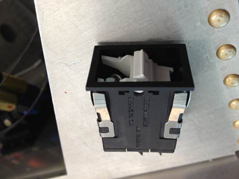
I bought these Honeywell illuminated rocker switches


[img]cid:image002.jpg(at)01CF03E0.8591B470[/img]


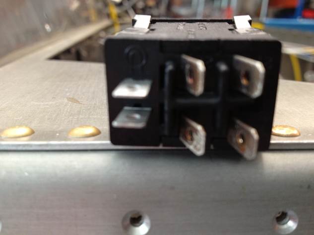
which are DPST switches, ref. # AML34 FBA4AC01, and look like this from behind


[img]cid:image004.jpg(at)01CF03E0.8591B470[/img]


The 4 inclinated lugs are obviously the source and load for each pole, but I’m having trouble to find out how to connect the upper lugs, i.e, how does the illumination lamp circuit works.

I suppose I’m having a brain freeze here…

Since they didn’t come with any schematic drawing, and I couldn’t find it online, can somebody please tell me (or send a hand draw) how does the lamp circuit works?


Thanks

Carlos
| | - The Matronics AeroElectric-List Email Forum - | | | Use the List Feature Navigator to browse the many List utilities available such as the Email Subscriptions page, Archive Search & Download, 7-Day Browse, Chat, FAQ, Photoshare, and much more:
http://www.matronics.com/Navigator?AeroElectric-List |
|
| Description: |
|
| Filesize: |
17.37 KB |
| Viewed: |
7198 Time(s) |
|
| Description: |
|
| Filesize: |
24.02 KB |
| Viewed: |
7198 Time(s) |
|
|
|
| Back to top |
|
 |
nuckolls.bob(at)aeroelect
Guest
|
 Posted: Sat Dec 28, 2013 7:55 am Post subject: Illuminated rocker switch Posted: Sat Dec 28, 2013 7:55 am Post subject: Illuminated rocker switch |
 |
|
| Quote: |
The 4 inclinated lugs are obviously the source
and load for each pole, but I’m having trouble
to find out how to connect the upper lugs, i.e,
how does the illumination lamp circuit works.
I suppose I’m having a brain freeze here…
Since they didn’t come with any schematic
drawing, and I couldn’t find it online, can
somebody please tell me (or send a hand draw) how does the lamp circuit works?
|
See http://tinyurl.com/mxhhc4c
You'll find two AML documents there that
will probably cover your questions.
Bob . . .
| | - The Matronics AeroElectric-List Email Forum - | | | Use the List Feature Navigator to browse the many List utilities available such as the Email Subscriptions page, Archive Search & Download, 7-Day Browse, Chat, FAQ, Photoshare, and much more:
http://www.matronics.com/Navigator?AeroElectric-List |
|
|
|
| Back to top |
|
 |
billp(at)wwpc.com
Guest
|
 Posted: Sat Dec 28, 2013 8:08 am Post subject: Illuminated rocker switch Posted: Sat Dec 28, 2013 8:08 am Post subject: Illuminated rocker switch |
 |
|
From the Digikey web site... - Bill
On 12/28/13, 7:22 AM, Carlos Trigo wrote:
| | - The Matronics AeroElectric-List Email Forum - | | | Use the List Feature Navigator to browse the many List utilities available such as the Email Subscriptions page, Archive Search & Download, 7-Day Browse, Chat, FAQ, Photoshare, and much more:
http://www.matronics.com/Navigator?AeroElectric-List |
|
| Description: |
|

Download |
| Filename: |
aml.10.20.30.series.chart.1.pdf |
| Filesize: |
121.35 KB |
| Downloaded: |
342 Time(s) |
| Description: |
|

Download |
| Filename: |
aml_30.pdf |
| Filesize: |
418.66 KB |
| Downloaded: |
324 Time(s) |
|
|
| Back to top |
|
 |
trigo(at)mail.telepac.pt
Guest
|
 Posted: Sat Dec 28, 2013 8:12 am Post subject: Illuminated rocker switch Posted: Sat Dec 28, 2013 8:12 am Post subject: Illuminated rocker switch |
 |
|
Bob

Thank you for your quick answer.


I already had grabed those 2 documents over the internet, and in none of them I was able to conclude how does the lamp circuit works, and how shall I wire these critters to get them illuminated…


Could you draw a simple hand sketch?


Carlos


--
| | - The Matronics AeroElectric-List Email Forum - | | | Use the List Feature Navigator to browse the many List utilities available such as the Email Subscriptions page, Archive Search & Download, 7-Day Browse, Chat, FAQ, Photoshare, and much more:
http://www.matronics.com/Navigator?AeroElectric-List |
|
|
|
| Back to top |
|
 |
trigo(at)mail.telepac.pt
Guest
|
 Posted: Sat Dec 28, 2013 8:37 am Post subject: Illuminated rocker switch Posted: Sat Dec 28, 2013 8:37 am Post subject: Illuminated rocker switch |
 |
|
Thanks Bill
But those are the same documents that Bob has pointed out, the first is only a drawing with physical dimensions of the switches, and from the other one I am not able to understand how the lamp circuit works..
Carlos
From: owner-aeroelectric-list-server(at)matronics.com [mailto:owner-aeroelectric-list-server(at)matronics.com] On Behalf Of Bill Putney
Sent: sábado, 28 de Dezembro de 2013 16:07
To: aeroelectric-list(at)matronics.com
Subject: Re: Illuminated rocker switch
From the Digikey web site... - Bill
On 12/28/13, 7:22 AM, Carlos Trigo wrote:
[quote][b]
| | - The Matronics AeroElectric-List Email Forum - | | | Use the List Feature Navigator to browse the many List utilities available such as the Email Subscriptions page, Archive Search & Download, 7-Day Browse, Chat, FAQ, Photoshare, and much more:
http://www.matronics.com/Navigator?AeroElectric-List |
|
|
|
| Back to top |
|
 |
racerjerry
Joined: 15 Dec 2009
Posts: 202
Location: Deer Park, NY
|
 Posted: Sat Dec 28, 2013 8:43 am Post subject: Re: Illuminated rocker switch Posted: Sat Dec 28, 2013 8:43 am Post subject: Re: Illuminated rocker switch |
 |
|
Hi Carlos,

It would be helpful if you would provide any markings shown on the switch housing / packaging.


At the bottom of the download document aml_30.pdf, on page 4, it shows connections for the internal light.  On many switches, the lamp circuit is independent of the switch circuit.  I am guessing that you have an isolated lamp circuit and that the two straight terminals are for the internal light.


Hope that this helps.  Have a great new year.


Jerry King
| | - The Matronics AeroElectric-List Email Forum - | | | Use the List Feature Navigator to browse the many List utilities available such as the Email Subscriptions page, Archive Search & Download, 7-Day Browse, Chat, FAQ, Photoshare, and much more:
http://www.matronics.com/Navigator?AeroElectric-List |
|
_________________
Jerry King |
|
| Back to top |
|
 |
trigo(at)mail.telepac.pt
Guest
|
 Posted: Sat Dec 28, 2013 9:00 am Post subject: Illuminated rocker switch Posted: Sat Dec 28, 2013 9:00 am Post subject: Illuminated rocker switch |
 |
|
Jerry


In that case, the switch light is not commanded by the switch itself, isn't

it?

So, if I want the lamp to illuminate when I turn On the switch, I'll have to

wire that externally. Am I correct?


Carlos

--
| | - The Matronics AeroElectric-List Email Forum - | | | Use the List Feature Navigator to browse the many List utilities available such as the Email Subscriptions page, Archive Search & Download, 7-Day Browse, Chat, FAQ, Photoshare, and much more:
http://www.matronics.com/Navigator?AeroElectric-List |
|
|
|
| Back to top |
|
 |
racerjerry
Joined: 15 Dec 2009
Posts: 202
Location: Deer Park, NY
|
 Posted: Sat Dec 28, 2013 9:40 am Post subject: Re: Illuminated rocker switch Posted: Sat Dec 28, 2013 9:40 am Post subject: Re: Illuminated rocker switch |
 |
|
YES and YES BUT
Oops again
I re-read your post & p 4 and see your switch AML34 FBA4AC01 is a:
AML 34 F > “Rectangular 1 lamp circuit”
B > “Black”
A > “No lamp installed”
4 > “.187 x .020 (Solder of Quick-Connect) terminal
AC > “2-Pole”
01 > maintained ON and OFF
I find the second “A” intriguing, as it hints that NO incandescent lamp was installed?? Honeywell MAY be using the same body on multiple switches and your switch MAY have lighting terminals, but no light installed. Try a resistance measurement between the two straight terminals. An incandescent light should give a relatively low resistance reading.
Jerry King
| | - The Matronics AeroElectric-List Email Forum - | | | Use the List Feature Navigator to browse the many List utilities available such as the Email Subscriptions page, Archive Search & Download, 7-Day Browse, Chat, FAQ, Photoshare, and much more:
http://www.matronics.com/Navigator?AeroElectric-List |
|
_________________
Jerry King |
|
| Back to top |
|
 |
Bob McC
Joined: 09 Jan 2006
Posts: 258
Location: Toronto, ON
|
 Posted: Sat Dec 28, 2013 9:48 am Post subject: Illuminated rocker switch Posted: Sat Dec 28, 2013 9:48 am Post subject: Illuminated rocker switch |
 |
|
Carlos;


Correct


Bob McC


[quote] --
| | - The Matronics AeroElectric-List Email Forum - | | | Use the List Feature Navigator to browse the many List utilities available such as the Email Subscriptions page, Archive Search & Download, 7-Day Browse, Chat, FAQ, Photoshare, and much more:
http://www.matronics.com/Navigator?AeroElectric-List |
|
_________________
Bob McC
Falco #908
(just starting) |
|
| Back to top |
|
 |
nuckolls.bob(at)aeroelect
Guest
|
 Posted: Sat Dec 28, 2013 10:09 am Post subject: Illuminated rocker switch Posted: Sat Dec 28, 2013 10:09 am Post subject: Illuminated rocker switch |
 |
|
At 10:11 AM 12/28/2013, you wrote:
| Quote: | Bob
Thank you for your quick answer.
I already had grabed those 2 documents over the internet, and in none of them I was able to conclude how does the lamp circuit works, and how shall I wire these critters to get them illuminated…
Could you draw a simple hand sketch?
|
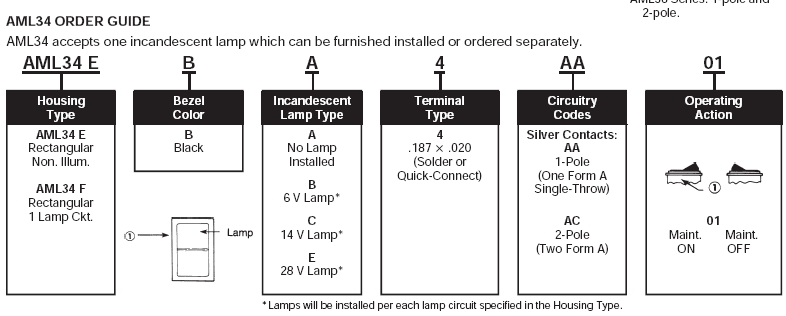
According to the number you cited, the switches you have
are black, rectangular devices with one lamp circuit, no
lamp installed, with .187 fast-on terminals and two Form A
contacts (two poles).
[img]cid:.0[/img]
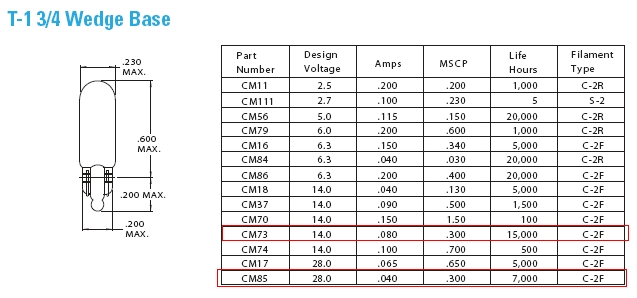
I presume you have #73 or #85 lamps to install
[img]cid:.1[/img]
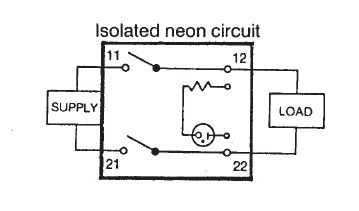
The schematic for these switches
[img]cid:.2[/img]
Shows the two poles on terminals 11/12 and 21/22 with
the lamp isolated on the other two terminals. The elsewhere
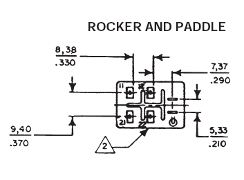
in the literature I found this rear view of the termina
arrangement
[img]cid:.3[/img]
If you look at the back of your switches, you'll probably
find numbers molded into the housings.
You probably only need one of the two poles to switch
a load so you can use either the 11/12 or 21/22 path
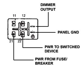
for this task. I presume that you're going to power all
the lights from a dimmer so one of the two lamp terminals
would be tied to ground . . . the other to your dimmer
output. For side-by-side switches, you can daisy-chain
jumpers across the row of switches to parallel all the
lamps and take single conductors to ground and dimmer.
. . . sorta like this.
[img]cid:.4[/img]
Bob . . .
| | - The Matronics AeroElectric-List Email Forum - | | | Use the List Feature Navigator to browse the many List utilities available such as the Email Subscriptions page, Archive Search & Download, 7-Day Browse, Chat, FAQ, Photoshare, and much more:
http://www.matronics.com/Navigator?AeroElectric-List |
|
| Description: |
|
| Filesize: |
105.4 KB |
| Viewed: |
7166 Time(s) |
|
| Description: |
|
| Filesize: |
102.54 KB |
| Viewed: |
7166 Time(s) |
|
| Description: |
|
| Filesize: |
27.12 KB |
| Viewed: |
7166 Time(s) |
|
| Description: |
|
| Filesize: |
32.4 KB |
| Viewed: |
7166 Time(s) |
|
| Description: |
|
| Filesize: |
24.43 KB |
| Viewed: |
7166 Time(s) |
|
|
|
| Back to top |
|
 |
Bob McC
Joined: 09 Jan 2006
Posts: 258
Location: Toronto, ON
|
 Posted: Sat Dec 28, 2013 10:17 am Post subject: Illuminated rocker switch Posted: Sat Dec 28, 2013 10:17 am Post subject: Illuminated rocker switch |
 |
|
Carlos;


Referring to the document AML30.pdf and analyzing the part number you have provided shows that you bought the switch without a lamp installed indicated by the "A" in the centre of the part number. You did buy the appropriate lamp to install in this switch according to the voltage you require didn't you? If you wished it to come with a 12V lamp already installed the central “A” should have been a “C”


AML34 ORDER GUIDE

AML34 accepts one incandescent lamp which can be furnished installed or ordered separately.

AML34 F B A 4 AC 01 has no lamp installed AML34 F B C 4 AC 01 has a 12V lamp installed. For 28 volt it would be an “E”


Bob McC

      [quote][b]
| | - The Matronics AeroElectric-List Email Forum - | | | Use the List Feature Navigator to browse the many List utilities available such as the Email Subscriptions page, Archive Search & Download, 7-Day Browse, Chat, FAQ, Photoshare, and much more:
http://www.matronics.com/Navigator?AeroElectric-List |
|
_________________
Bob McC
Falco #908
(just starting) |
|
| Back to top |
|
 |
Mauledriver(at)nc.rr.com
Guest
|
 Posted: Sat Dec 28, 2013 10:18 am Post subject: Illuminated rocker switch Posted: Sat Dec 28, 2013 10:18 am Post subject: Illuminated rocker switch |
 |
|
In AML 24, 34 and 26 (you probably have AML24)  any light circuits are

independent of the switch circuits.  Looking at the spec sheet, they

only show the diagram for the various switched poles.  You just hook up

the lights directly to power and ground and possibly a dimmer.  I don't

think I ever saw a diagram showing the light circuit.


The AML36 series has versions where the lamp circuit is integral to

switch circuit.  I'm unfamiliar with those.


I used a number AML 24 and 34 switches, all with independent lamp

circuits.  I had no desire to have the light do anything other than

light up the switch label for night ops.


My switches were spec'd for incandescent lamps, however I replaced them

with LED lamps with integral resistors sourced from one of the panel

shops.  They are also dimmed with units from Perihelion.


If you need indicator lamps, the AML41 indicators are a nice complement.


The dimming is critical.  A bank of these switches and/or indicators

will blind you at night.  At the same time, they are very nice at night

when properly dimmed.  Re the indicators, I did not dim the 'warning'

and 'fault' indicators, i.e. Oil Press, Low Voltage, Master Warn, Door

Open, because they should be seen no matter how the dimmer is set.  I

did dim the 'status' indicators, i.e. Buss Crossfeed and Boost Pump,

because I didn't want to be blinded when those indicators are on for

extended periods.


Here is a page showing some switch wiring - note that none of the switch

terminals are connected, only the light circuits are wired.

http://www.mykitlog.com/users/display_log.php?user=MauleDriver&project=224&category=5253&log=122434&row=2


Here a page showing the switches and indicator lights on the panel

(while under construction)

http://www.mykitlog.com/users/display_log.php?user=MauleDriver&project=224&category=5253&log=91400&row=6

On 12/28/2013 11:59 AM, Carlos Trigo wrote:

[quote]


 Jerry


 In that case, the switch light is not commanded by the switch itself, isn't

 it?

 So, if I want the lamp to illuminate when I turn On the switch, I'll have to

 wire that externally. Am I correct?


 Carlos

 --
| | - The Matronics AeroElectric-List Email Forum - | | | Use the List Feature Navigator to browse the many List utilities available such as the Email Subscriptions page, Archive Search & Download, 7-Day Browse, Chat, FAQ, Photoshare, and much more:
http://www.matronics.com/Navigator?AeroElectric-List |
|
|
|
| Back to top |
|
 |
trigo(at)mail.telepac.pt
Guest
|
 Posted: Sat Dec 28, 2013 4:57 pm Post subject: Illuminated rocker switch Posted: Sat Dec 28, 2013 4:57 pm Post subject: Illuminated rocker switch |
 |
|
Thanks to all who responded. As usual you've been very helpful.
Now that I know the lamp circuit is independent from the 2 poles, I will have to design my wiring for the illumination to work as I had planned.
Back to the bench
Carlos
Enviado do meu iPhone
No dia 28/12/2013, Ă s 18:05, "Robert L. Nuckolls, III" <nuckolls.bob(at)aeroelectric.com (nuckolls.bob(at)aeroelectric.com)> escreveu:
[quote] At 10:11 AM 12/28/2013, you wrote:
| Quote: | Bob
Thank you for your quick answer.
I already had grabed those 2 documents over the internet, and in none of them I was able to conclude how does the lamp circuit works, and how shall I wire these critters to get them illuminated…
Could you draw a simple hand sketch?
|
According to the number you cited, the switches you have
are black, rectangular devices with one lamp circuit, no
lamp installed, with .187 fast-on terminals and two Form A
contacts (two poles).
<6c7bf9.jpg>
I presume you have #73 or #85 lamps to install
<6c7c56.jpg>
The schematic for these switches
<6c7cb4.jpg>
Shows the two poles on terminals 11/12 and 21/22 with
the lamp isolated on the other two terminals. The elsewhere
in the literature I found this rear view of the termina
arrangement
<6c7ce3.jpg>
If you look at the back of your switches, you'll probably
find numbers molded into the housings.
You probably only need one of the two poles to switch
a load so you can use either the 11/12 or 21/22 path
for this task. I presume that you're going to power all
the lights from a dimmer so one of the two lamp terminals
would be tied to ground . . . the other to your dimmer
output. For side-by-side switches, you can daisy-chain
jumpers across the row of switches to parallel all the
lamps and take single conductors to ground and dimmer.
. . . sorta like this.
<6c7d12.jpg>
Bob . . .
[b]
| | - The Matronics AeroElectric-List Email Forum - | | | Use the List Feature Navigator to browse the many List utilities available such as the Email Subscriptions page, Archive Search & Download, 7-Day Browse, Chat, FAQ, Photoshare, and much more:
http://www.matronics.com/Navigator?AeroElectric-List |
|
|
|
| Back to top |
|
 |
|
|
You cannot post new topics in this forum
You cannot reply to topics in this forum
You cannot edit your posts in this forum
You cannot delete your posts in this forum
You cannot vote in polls in this forum
You cannot attach files in this forum
You can download files in this forum
|
Powered by phpBB © 2001, 2005 phpBB Group
|


