 |
Matronics Email Lists
Web Forum Interface to the Matronics Email Lists
|
| View previous topic :: View next topic |
| Author |
Message |
lgold(at)quantum-associat
Guest
|
 Posted: Thu Jan 02, 2014 10:39 am Post subject: Viking engine duel battery setup Posted: Thu Jan 02, 2014 10:39 am Post subject: Viking engine duel battery setup |
 |
|
Hi Robert,
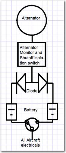
I know you have concerns about the Viking engine’s electrical system. But I purchased a Zenith aircraft with this engine and want to make the plane as safe as I can. The engine is an “aircraftized” Honda Fit with fuel injection. Since the engine will stop is a fuel pump fails Jan Eggenfeller specified duel redundant fuel pumps and the ability to switch pumps. However, there are no previsions for a duel battery circuit or a way to isolate the battery in case of an alternator fault.
I would like to install two batteries that are both charged from the 55-Amp alternator and also be able to select the battery that powers the plane’s electricals and to isolate the batteries by disconnecting a faulty alternator in flight. I previously built a plane with a Rotax 912 using your wiring diagram, (after attending your great seminar). The Rotax diagram had battery isolation capabilities and was wondering of any of your wiring diagrams describe how to do this for my Viking engine or, if not, can you explain how I can do this properly or at least specify the diodes I need to install in the attached diagram.
Thank you for your help,
Les Goldner
[img]cid:image003.jpg(at)01CF07A6.567864D0[/img]
| | - The Matronics AeroElectric-List Email Forum - | | | Use the List Feature Navigator to browse the many List utilities available such as the Email Subscriptions page, Archive Search & Download, 7-Day Browse, Chat, FAQ, Photoshare, and much more:
http://www.matronics.com/Navigator?AeroElectric-List |
|
| Description: |
|
| Filesize: |
20.6 KB |
| Viewed: |
8845 Time(s) |
|
|
|
| Back to top |
|
 |
nuckolls.bob(at)aeroelect
Guest
|
| Posted: Fri Jan 03, 2014 4:58 am Post subject: Viking engine duel battery setup |
|
|
At 12:35 PM 1/2/2014, you wrote:


Hi Robert,


I know you have concerns about the Viking engine's electrical system.


    The Viking engine a derivative of

    the Eggenfellner venture which has

    suffered a checkered history from

    the perspectives of both business

    model and engineering . . .


http://tinyurl.com/qclebez


http://tinyurl.com/qclebez


    Yes, I have come 'concerns' that extend far beyond

    the 'electrical system'.


But I purchased a Zenith aircraft with this engine and want to make

the plane as safe as I can. The engine is an "aircraftized" Honda Fit

with fuel injection. Since the engine will stop is a fuel pump fails

Jan Eggenfeller specified duel redundant fuel pumps and the ability

to switch pumps. However, there are no previsions for a duel battery

circuit or a way to isolate the battery in case of an alternator fault.


    Your premise for needing two batteries or needing

    to 'isolate them' from a faulted alternator begs

    more detailed examination. Alternator 'faults' are

    exceedingly rare these days and are generally limited

    to mechanical issues (belts and mounts) and wiring

    (the thing simply shuts down). There's a small risk

    for an overvoltage condition which is classically

    managed with a legacy o.v. sense and response system

    that has been part and parcel of aircraft alternator

    and generator systems for 60+ years.


    There is even a smaller probability of a shorted/

    open  diode array that will either (1) reduce the

    alternator's output severely or (2) short the battery

    to ground. The both cases will probably manifest with

    a low voltage warning with the second case opening

    the b-lead fuse.


    In other words, there are no demonstrated alternator

    faults that go beyond simple failure to function . . .

    a condition that does not propagate damage or operational

    stress to other parts of the system. Hence, no additional

    form of 'isolation' is indicated.


    There was some discussions and analysis conducted on

    the aviation special interest groups about 18 years

    ago concerning the use of diode isolation (ala RV

    and boat batteries) for dual batteries on airplanes.


http://tinyurl.com/oss5t4u

I would like to install two batteries that are both charged from the

55-Amp alternator and also be able to select the battery that powers

the plane's electricals and to isolate the batteries by disconnecting

a faulty alternator in flight. I previously built a plane with a

Rotax 912 using your wiring diagram, (after attending your great

seminar). The Rotax diagram had battery isolation capabilities and

was wondering of any of your wiring diagrams describe how to do this

for my Viking engine or, if not, can you explain how I can do this

properly or at least specify the diodes I need to install in the

attached diagram.


    You would be well advised to search out, study,

    and understand all of the failure modes that

    might cause this engine to cease operation . . .

    both electrical AND mechanical.


    Then rank them in order of probability. Yes

    there will be a pile of "don't know" for

    probability but at least you have the item

    on the list.


    The only time I've seen an Eggenfellner

    design installed on an aircraft gave me an

    opportunity to take this picture . . .


http://tinyurl.com/p5dgz43


    The installation gives rise to concerns

    for gross complexity (failure risk proportional

    to parts count) as well as operational

    reliability. Relays generally don't find

    their way into the control of critical circuits

    on any engine installation, aviation or

    otherwise. The fact that this engine seemed

    to be 'blessed' with over a dozen such devices

    is cause for further examination and understanding.


    The point to being offered here is that past

    history for Eggenfellner designs suggests

    that there may be numerous failure modes

    that go beyond simple concerns for keeping

    the fuel pumps powered.


    We've had some discussions here recently on

    electrical system reliability for the electrically

    dependent engine . . . exploring the notion

    that a well maintained, single battery/alternator

    system has a very low failure rate on a par with

    other components that might cause engine failure.


    A new Z-figure . . .


http://tinyurl.com/kbn6bys


    . . . is in it's 5th refinement iteration

    and I'm pretty confident that it's final configuration

    will be suited to your installation as well without

    suffering the weight and cost of ownership penalties

    for carrying two batteries . . . just to address

    one of many failure modes.


    Are the wiring diagrams provided with your engine

    available on the 'net? If not, can you scan your

    documents for sharing?


  Bob . . .
| | - The Matronics AeroElectric-List Email Forum - | | | Use the List Feature Navigator to browse the many List utilities available such as the Email Subscriptions page, Archive Search & Download, 7-Day Browse, Chat, FAQ, Photoshare, and much more:
http://www.matronics.com/Navigator?AeroElectric-List |
|
|
|
| Back to top |
|
|
kleh(at)dialupatcost.ca
Guest
|
| Posted: Fri Jan 03, 2014 5:57 am Post subject: Viking engine duel battery setup |
|
|
Minor point and I have not dealt with anything newer than 2002, but
every EFI vehicle I've worked on had at least one relay that controlled
essential engine circuits. My aircraft backup EFI does not have any
relays but my primary oem soob efi has the same two as it had in the
car. As far as I could determine, the oem relays have outstanding
reliability.
Have newer vehicles gone to solid state relays?
Ken
On 03/01/2014 7:57 AM, Robert L. Nuckolls, III wrote:
| Quote: | Relays generally don't find their way into the control of critical
> circuits on any engine installation, aviation or otherwise. The fact
|
> that this engine seemed to be 'blessed' with over a dozen such
> devices is cause for further examination and understanding.
| | - The Matronics AeroElectric-List Email Forum - | | | Use the List Feature Navigator to browse the many List utilities available such as the Email Subscriptions page, Archive Search & Download, 7-Day Browse, Chat, FAQ, Photoshare, and much more:
http://www.matronics.com/Navigator?AeroElectric-List |
|
|
|
| Back to top |
|
|
nuckolls.bob(at)aeroelect
Guest
|
| Posted: Fri Jan 03, 2014 7:36 am Post subject: Viking engine duel battery setup |
|
|
At 07:57 AM 1/3/2014, you wrote:
| Quote: |
Minor point and I have not dealt with anything newer than 2002, but
every EFI vehicle I've worked on had at least one relay that
controlled essential engine circuits. My aircraft backup EFI does
not have any relays but my primary oem soob efi has the same two as
it had in the car. As far as I could determine, the oem relays have
outstanding reliability.
Have newer vehicles gone to solid state relays?
|
I don't know . . . but it's coming. Waaayyyyy
back when, I was finishing up the qualification
paperwork for a pitch trim control system on the
Lears. One of my colleagues was working the Mil-Hdbk-
217 MTBF studies on the design.
He had factored in all the jelly-beans, solder joints,
integrated circuits, and transistors . . . so far so
good . . . MTBF was running about 9,000 hours. THEN
he factored in a mil-spec, hermetically sealed, power
relay . . . whoops! MTBF dropped to about 900 hours!
Seems relays are not highly regarded devices in terms
of impact on reliability. However, the study protocols
did not consider the manner in which I was using the
device . . . it was energized before any current was
allowed to flow in the contacts . . . and de-energized
after current flow ceased. In other words, it never
SWITCHED a load, only carried a load but was available
for responding to the Wheel-Master-Disconnect switch
shutting system down in case of a runaway.
To my knowledge, 30+ years later, no relays have ever
been replaced. The speed control system has proven
very robust also but the monitor system (4x parts count)
and some mechanical environmental issues (box is
mounted in vertical fin under the trim actuator)
have required attention.
Ergo, my statement about the use of relays was perhaps
too broad . . . or at least lacking details. We attempt
to reduce numbers of these things to a minimum . . . they
are after all a mechanical device with moving, arcing
parts. However, there are design concessions for de-rating,
dry-switching, duty-cycle, etc. that go a long way toward
boosting relay reliability.
To be sure, nobody has more interest in component
reliability than the automotive industry. An AD
against an airplane generally involves fewer than
100 airplanes . . . recalls on cars can number
in the millions. I helped some guys qualify an
automotive seat heater onto a Hawker some years
back . . . the specs to which the seat had already
been qualified were impressive! But you wanna put
it on our airplane? Guess what? There's that 80v
surge thingy . . .
I helped them craft an automatic disconnect circuit
that isolated their vulnerable components during
the surge event.
So your observation is on-point. Relays are not
to be shunned out of hand . . . but consider also
the lengths that talented users of relays will
exercise to make them capable players in the
game.
Track records for the purveyors is important.
Just because it's used on a car is not an automatic
pass. A fuse block in my wife's AMC Pacer damned near
set the car on fire . . . twice . . . before I
replaced it.
So let me re-qualify my original reaction to the
photo of Eggenfellner's installation. Given the
gross numbers of relays combined with his track
record, I will suggest that there is cause for
placing ALL of his intellectual and physical product
under the microscope.
Bob . . .
| | - The Matronics AeroElectric-List Email Forum - | | | Use the List Feature Navigator to browse the many List utilities available such as the Email Subscriptions page, Archive Search & Download, 7-Day Browse, Chat, FAQ, Photoshare, and much more:
http://www.matronics.com/Navigator?AeroElectric-List |
|
|
|
| Back to top |
|
|
deej(at)deej.net
Guest
|
| Posted: Fri Jan 03, 2014 8:51 am Post subject: Viking engine duel battery setup |
|
|
On 1/3/2014 7:57 AM, Robert L. Nuckolls, III wrote:
| Quote: |
The only time I've seen an Eggenfellner
design installed on an aircraft gave me an
opportunity to take this picture . . .
http://tinyurl.com/p5dgz43
|
Are you sure that is a picture of an Eggenfellner installation? It
doesn't look like any Eggenfellner setups that I've seen, but it does
resemble an older NSI setup that I saw at OSH or Sun-n-Fun some years back.
At any rate, it is certainly not typical of what is being installed to
support Subaru engines (Eggenfellner or otherwise) these days. The
Aeroelectric Connection is often used as a reference on the Subaru
lists, but if you want to see the last recommended electrical design
that came from Eggenfellner before they went out of business, you can
download the installation guide from:
http://subenews.deej.net/wiki/index.php/EggH6
Click on the "Eggenfellner Engine Installation Guide" (top link under
the under the Howto Guides section), and go to page 45, and page 51 has
the electrical schematic.
Please note this is not an endorsement, just an informational posting. 
fyi
-Dj
--
Dj Merrill - N1JOV - VP EAA Chapter 87
Sportsman 2+2 Builder #7118 N421DJ - http://deej.net/sportsman/
Glastar Flyer N866RH - http://deej.net/glastar/
| | - The Matronics AeroElectric-List Email Forum - | | | Use the List Feature Navigator to browse the many List utilities available such as the Email Subscriptions page, Archive Search & Download, 7-Day Browse, Chat, FAQ, Photoshare, and much more:
http://www.matronics.com/Navigator?AeroElectric-List |
|
|
|
| Back to top |
|
|
jluckey(at)pacbell.net
Guest
|
| Posted: Fri Jan 03, 2014 9:29 am Post subject: Viking engine duel battery setup |
|
|
It should be noted that the primary reason for such circuitry is to prevent paralleling the two independent batteries thru the charging system.
From: Les Goldner <lgold(at)quantum-associates.com>
To: Aeroelectric list <aeroelectric-list(at)matronics.com>
Sent: Thursday, January 2, 2014 10:35 AM
Subject: Viking engine duel battery setup
Hi Robert,
I know you have concerns about the Viking engineâs electrical system. But I purchased a Zenith aircraft with this engine and want to make the plane as safe as I can. The engine is an âaircraftizedâ Honda Fit with fuel injection. Since the engine will stop is a fuel pump fails Jan Eggenfeller specified duel redundant fuel pumps and the ability to switch pumps. However, there are no previsions for a duel battery circuit or a way to isolate the battery in case of an alternator fault.
I would like to install two batteries that are both charged from the 55-Amp alternator and also be able to select the battery that powers the planeâs electricals and to isolate the batteries by disconnecting a faulty alternator in flight. I previously built a plane with a Rotax 912 using your wiring diagram, (after attending your great seminar). The Rotax diagram had battery isolation capabilities and was wondering of any of your wiring diagrams describe how to do this for my Viking engine or, if not, can you explain how I can do this properly or at least specify the diodes I need to install in the attached diagram.
Thank you for your help,
Les Goldner
[img]cid:1.1668915207(at)web184906.mail.gq1.yahoo.com[/img]
| | - The Matronics AeroElectric-List Email Forum - | | | Use the List Feature Navigator to browse the many List utilities available such as the Email Subscriptions page, Archive Search & Download, 7-Day Browse, Chat, FAQ, Photoshare, and much more:
http://www.matronics.com/Navigator?AeroElectric-List |
|
| Description: |
|
| Filesize: |
20.6 KB |
| Viewed: |
8820 Time(s) |

|
|
|
| Back to top |
|
|
nuckolls.bob(at)aeroelect
Guest
|
| Posted: Fri Jan 03, 2014 10:13 am Post subject: Viking engine duel battery setup |
|
|
At 11:28 AM 1/3/2014, you wrote:
| Quote: | It should be noted that the primary reason for such circuitry is to
prevent paralleling the two independent batteries thru the charging system.
|
Why would one want to do that?
Bob . . .
| | - The Matronics AeroElectric-List Email Forum - | | | Use the List Feature Navigator to browse the many List utilities available such as the Email Subscriptions page, Archive Search & Download, 7-Day Browse, Chat, FAQ, Photoshare, and much more:
http://www.matronics.com/Navigator?AeroElectric-List |
|
|
|
| Back to top |
|
|
nuckolls.bob(at)aeroelect
Guest
|
| Posted: Fri Jan 03, 2014 10:15 am Post subject: Viking engine duel battery setup |
|
|
Are you sure that is a picture of an Eggenfellner installation?  It

doesn't look like any Eggenfellner setups that I've seen, but it does

resemble an older NSI setup that I saw at OSH or Sun-n-Fun some years back.


   Actually, I'm not. I saw the airplane on display

   at an airport where I was giving a weekend seminar.

   I snapped the picture to use in the seminar as an

   example of an installation that would benefit from

   some judicious review.


At any rate, it is certainly not typical of what is being installed

to support Subaru engines (Eggenfellner or otherwise) these days. The

Aeroelectric Connection is often used as a reference on the Subaru

lists, but if you want to see the last recommended electrical design

that came from Eggenfellner before they went out of business, you can

download the installation guide from:


   Thanks for the heads-up! With all due respect

   to Jan's work, my apologies for any errors of

   attribution.


http://subenews.deej.net/wiki/index.php/EggH6


Click on the "Eggenfellner Engine Installation Guide" (top link under

the under the Howto Guides section), and go to page 45, and page 51

has the electrical schematic.


Please note this is not an endorsement, just an informational posting.


   And good information it is my friend. I'll study the drawings

   and incorporate the information into a follow-up posting. This

   dovetails nicely with the discussions we're having about

   Fred's incorporation of the ExpBus in his electrically dependent

   airplane.


   Fred provided some asked-for info on his installation

   which I've not yet had time to consider . . . but it's

   on the list.

   Bob . . .
| | - The Matronics AeroElectric-List Email Forum - | | | Use the List Feature Navigator to browse the many List utilities available such as the Email Subscriptions page, Archive Search & Download, 7-Day Browse, Chat, FAQ, Photoshare, and much more:
http://www.matronics.com/Navigator?AeroElectric-List |
|
|
|
| Back to top |
|
|
lgold(at)quantum-associat
Guest
|
| Posted: Fri Jan 03, 2014 10:30 am Post subject: Viking engine duel battery setup |
|
|
Thanks for the information Robert.
There is nothing in the Viking engine that looks anything as complex as the
picture you included in your last email. In fact, the physical electricals
provided with the Viking engine look very "clean".
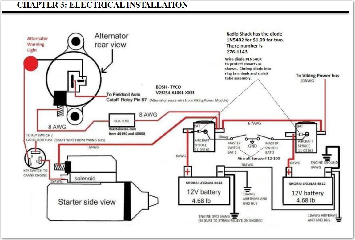
You asked to see the Viking wiring diagrams so I attached two diagrams Jan
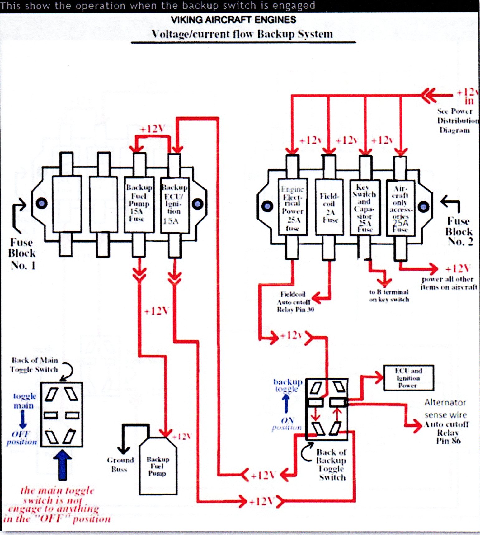
Eggenfeller provided for the Viking engine. The diagram named "Backup
System" is a very nice looking module provided with the Viking engine for
redundancy to control two fuel pumps (I think it also controls a duel ECUs)
in case one fails. The other diagram is more relevant to my questions to you
about having two batteries. It shows recommended power provisions,
including a second battery. I would appreciate your comments about employing
this two-battery arrangement?
Best regard,
Les
--
| | - The Matronics AeroElectric-List Email Forum - | | | Use the List Feature Navigator to browse the many List utilities available such as the Email Subscriptions page, Archive Search & Download, 7-Day Browse, Chat, FAQ, Photoshare, and much more:
http://www.matronics.com/Navigator?AeroElectric-List |
|
| Description: |
|
| Filesize: |
355.73 KB |
| Viewed: |
8818 Time(s) |
|
| Description: |
|
| Filesize: |
275.46 KB |
| Viewed: |
8818 Time(s) |
|
|
|
| Back to top |
|
|
teblejw
Joined: 19 Nov 2013
Posts: 14
|
| Posted: Fri Jan 03, 2014 10:30 am Post subject: Viking engine duel battery setup |
|
|
Bob,


You wrote:

"There's a small risk

   for an overvoltage condition which is classically

   managed with a legacy o.v. sense and response system

   that has been part and parcel of aircraft alternator

   and generator systems for 60+ years."

Yes, but the Viking has an auto-based system, with an integrated regulator.  You make the comment:

"In other words, there are no demonstrated alternator

   faults that go beyond simple failure to function . . .

   a condition that does not propagate damage or operational

   stress to other parts of the system. Hence, no additional

   form of 'isolation' is indicated."

Is this true?  Is there some  recent information that suggests that the "runaway" auto regulator is too unlikely to be an issue.  I've been planning for a "crowbar" and an expensive contactor for this potential event.  Am I overreacting?

Tom


[quote]

   From: "Robert L. Nuckolls, III" <nuckolls.bob(at)aeroelectric.com>

 To: aeroelectric-list(at)matronics.com

 Sent: Friday, January 3, 2014 5:57 AM

 Subject: Re: Viking engine duel battery setup


 --> AeroElectric-List message posted by: "Robert L. Nuckolls, III" <nuckolls.bob(at)aeroelectric.com (nuckolls.bob(at)aeroelectric.com)>


At 12:35 PM 1/2/2014, you wrote:


Hi Robert,


I know you have concerns about the Viking engine's electrical system.


   The Viking engine a derivative of

   the Eggenfellner venture which has

   suffered a checkered history from

   the perspectives of both business

   model and engineering . . .


http://tinyurl.com/qclebez


http://tinyurl.com/qclebez


   Yes, I have come 'concerns' that extend far beyond

   the 'electrical system'.


But I purchased a Zenith aircraft with this engine and want to make the plane as safe as I can. The engine is an "aircraftized" Honda Fit with fuel injection. Since the  engine will stop is a fuel pump fails Jan Eggenfeller specified duel redundant fuel pumps and the ability to switch pumps. However, there are no previsions for a duel battery circuit or a way to isolate the battery in case of an alternator fault.


   Your premise for needing two batteries or needing

   to 'isolate them' from a faulted alternator begs

   more detailed examination. Alternator 'faults' are

   exceedingly rare these days and are generally limited

   to mechanical issues (belts and mounts) and wiring

   (the thing simply shuts down). There's a small risk

   for an overvoltage condition which is classically

   managed with a legacy o.v. sense and response system

   that has been part and parcel of aircraft alternator

   and generator systems for 60+ years.


   There is even a smaller probability of a shorted/

   open  diode array that  will either (1) reduce the

   alternator's output severely or (2) short the battery

   to ground. The both cases will probably manifest with

   a low voltage warning with the second case opening

   the b-lead fuse.


   In other words, there are no demonstrated alternator

   faults that go beyond simple failure to function . . .

   a condition that does not propagate damage or operational

   stress to other parts of the system. Hence, no additional

   form of 'isolation' is indicated.


   There was some discussions and analysis conducted on

   the aviation special interest groups about 18 years

   ago concerning the use of diode isolation (ala RV

   and boat batteries) for dual batteries on airplanes.


http://tinyurl.com/oss5t4u

I would like to install two batteries that are both charged from the 55-Amp alternator and  also be able to select the battery that powers the plane's electricals and to isolate the batteries by disconnecting a faulty alternator in flight. I previously built a plane with a Rotax 912 using your wiring diagram, (after attending your great seminar). The Rotax diagram had battery isolation capabilities and was wondering of any of your wiring diagrams describe how to do this for my Viking engine or, if not, can you explain how I can do this properly or at least specify the diodes I need to install in the attached diagram.


   You would be well advised to search out, study,

   and understand all of the failure modes that

   might cause this engine to cease operation . . .

   both electrical AND mechanical.


   Then rank them in order of probability. Yes

   there will be a pile of "don't know" for

   probability but at least you have the item

   on the list.


   The only  time I've seen an Eggenfellner

   design installed on an aircraft gave me an

   opportunity to take this picture . . .


http://tinyurl.com/p5dgz43


   The installation gives rise to concerns

   for gross complexity (failure risk proportional

   to parts count) as well as operational

   reliability. Relays generally don't find

   their way into the control of critical circuits

   on any engine installation, aviation or

   otherwise. The fact that this engine seemed

   to be 'blessed' with over a dozen such devices

   is cause for further examination and understanding.


   The point to being offered here is that past

   history for Eggenfellner designs suggests

   that there may be numerous failure modes

   that go beyond simple concerns for keeping

   the fuel pumps powered.


   We've had some discussions  here recently on

   electrical system reliability for the electrically

   dependent engine . . . exploring the notion

   that a well maintained, single battery/alternator

   system has a very low failure rate on a par with

   other components that might cause engine failure.


   A new Z-figure . . .


http://tinyurl.com/kbn6bys


   . . . is in it's 5th refinement iteration

   and I'm pretty confident that it's final configuration

   will be suited to your installation as well without

   suffering the weight and cost of ownership penalties

   for carrying two batteries . . . just to address

   one of many failure modes.


   Are the wiring diagrams provided with your engine

   available on the 'net? If not, can you scan your

   documents for sharing?


 ion" sp;                     &//www.matronics.com/Navigator?AeroElectric-List" target="_blank">http://w--> http://fo=======================


 [b]
| | - The Matronics AeroElectric-List Email Forum - | | | Use the List Feature Navigator to browse the many List utilities available such as the Email Subscriptions page, Archive Search & Download, 7-Day Browse, Chat, FAQ, Photoshare, and much more:
http://www.matronics.com/Navigator?AeroElectric-List |
|
|
|
| Back to top |
|
|
jluckey(at)pacbell.net
Guest
|
| Posted: Fri Jan 03, 2014 11:50 am Post subject: Viking engine duel battery setup |
|
|
for many of the same reasons that (I imagine) you put a "buss tie" contactor in the Z-14 drawings.
From: "Robert L. Nuckolls, III" <nuckolls.bob(at)aeroelectric.com>
To: aeroelectric-list(at)matronics.com
Sent: Friday, January 3, 2014 10:11 AM
Subject: Re: Viking engine duel battery setup
--> AeroElectric-List message posted by: "Robert L. Nuckolls, III" <nuckolls.bob(at)aeroelectric.com (nuckolls.bob(at)aeroelectric.com)>
At 11:28 AM 1/3/2014, you wrote:
| Quote: | It should be noted that the primary reason for such circuitry is to prevent paralleling the two independent batteries thru the charging system.
|
Why would one want to do that? AeroElectric wwtarget="_blank" href="http://www.buildersbooks.com/">www.buildersbooks.bsp; * My Pilot Store
| | - The Matronics AeroElectric-List Email Forum - | | | Use the List Feature Navigator to browse the many List utilities available such as the Email Subscriptions page, Archive Search & Download, 7-Day Browse, Chat, FAQ, Photoshare, and much more:
http://www.matronics.com/Navigator?AeroElectric-List |
|
|
|
| Back to top |
|
|
nuckolls.bob(at)aeroelect
Guest
|
| Posted: Sat Jan 04, 2014 4:33 am Post subject: Viking engine duel battery setup |
|
|
At 12:29 PM 1/3/2014, you wrote:
| Quote: | Bob,
You wrote:
"There's a small risk
for an overvoltage condition which is classically
managed with a legacy o.v. sense and response system
that has been part and parcel of aircraft alternator
and generator systems for 60+ years."
|
| Quote: | Yes, but the Viking has an auto-based system, with an integrated
regulator. You make the comment:
"In other words, there are no demonstrated alternator
faults that go beyond simple failure to function . . .
a condition that does not propagate damage or operational
stress to other parts of the system. Hence, no additional
form of 'isolation' is indicated."
|
| Quote: | Is this true? Is there some recent information that suggests that
the "runaway" auto regulator is too unlikely to be an issue. I've
been planning for a "crowbar" and an expensive contactor for this
potential event. Am I overreacting?
|
The statements I made were in the context
of the discussion for 'isolation diodes' in the b-lead.
The incorporation of diodes external to the
alternator for the purpose of 'isolation' has
no foundation in the physics.
OV conditions are another matter. There ARE
failure modes within built in regulators which
are not sufficiently detailed to allow
incorporation of STOCK internally regulated
alternators into aircraft under the LEGACY
design goals.
If one embraces those goals then some understanding
of the options for ADDING ov protection to the
system is necessary. See:
http://tinyurl.com/nexuekf
http://tinyurl.com/cx6426c
There have been some interesting discussions
about design goals for system robustness and
the implementation of failure tolerance in
OBAM aircraft over the years. Some positions
were adopted by individuals unable to demonstrate
an understanding of failure tolerant design goals
. . .
http://tinyurl.com/7lhbbah
http://tinyurl.com/nexuekf
http://tinyurl.com/omnuypr
My goals and those of my employers over
the years has been to first reduce
probability of malfunction with
robust designs backed up by further reduction
of risks with failure tolerant designs.
Alternators are but one of many components
with an ability to elevate your concerns
while airborne . . . but easily managed.
Bob . . .
| | - The Matronics AeroElectric-List Email Forum - | | | Use the List Feature Navigator to browse the many List utilities available such as the Email Subscriptions page, Archive Search & Download, 7-Day Browse, Chat, FAQ, Photoshare, and much more:
http://www.matronics.com/Navigator?AeroElectric-List |
|
|
|
| Back to top |
|
|
nuckolls.bob(at)aeroelect
Guest
|
| Posted: Sat Jan 04, 2014 5:15 am Post subject: Viking engine duel battery setup |
|
|
At 01:49 PM 1/3/2014, you wrote:
| Quote: | for many of the same reasons that (I imagine) you put a "buss tie"
contactor in the Z-14 drawings.
|
But what might those reasons be? In other words, we
add a component to a system to effect some desired
functionality that figures into the overall performance,
failure tolerance and risks.
If diodes were incorporated in the manner suggested
to feed the two batteries, how would we expect these
to operate and for what purpose?
I'm not trying to be obtuse here my friend. I
AM encouraging all of my readers to understand
the application of every component they choose
to add to their system. Suppose I offered a description
for the buss-tie contactor like, "This contactor
offers pilot control of the phramistat to prevent
inadvertent operation of the whatsadozit and
potential damage to the dingusfuzzy."
The inquiring builder would probably want some
detailed expansion on that statement . . . un-
fortunately, others will assume the statement
correct and useful based on the reputation
(deserved or otherwise) of the writer.
I encourage yourself and others to KNOW why
a part is included and UNDERSTAND what useful
things it will do for you. Hence my question
as to any value you perceive for having those
diodes in place as suggested.
Bob . . .
| | - The Matronics AeroElectric-List Email Forum - | | | Use the List Feature Navigator to browse the many List utilities available such as the Email Subscriptions page, Archive Search & Download, 7-Day Browse, Chat, FAQ, Photoshare, and much more:
http://www.matronics.com/Navigator?AeroElectric-List |
|
|
|
| Back to top |
|
|
nuckolls.bob(at)aeroelect
Guest
|
| Posted: Sat Jan 04, 2014 6:10 am Post subject: Viking engine duel battery setup |
|
|
Not a problem Bob...I'm busying myself attempting to master

 the techniques necessary to assemble a 25 pin D-sub w/ mostly shielded wires...Fred


    Okay, I presume you've looked at this piece on

    the website.


  http://tinyurl.com/87lea6o


    The shields do not have to come together inside

    the connector back-shell. If there are a lot of them,

    you can have a couple inches of un-shielded wires

    allowing all the shield terminations to happen

    outside the back-shell.


   Bob . . .     [quote][b]
| | - The Matronics AeroElectric-List Email Forum - | | | Use the List Feature Navigator to browse the many List utilities available such as the Email Subscriptions page, Archive Search & Download, 7-Day Browse, Chat, FAQ, Photoshare, and much more:
http://www.matronics.com/Navigator?AeroElectric-List |
|
|
|
| Back to top |
|
|
nuckolls.bob(at)aeroelect
Guest
|
| Posted: Sat Jan 04, 2014 8:15 am Post subject: Viking engine duel battery setup |
|
|
[img]cid:.0[/img]
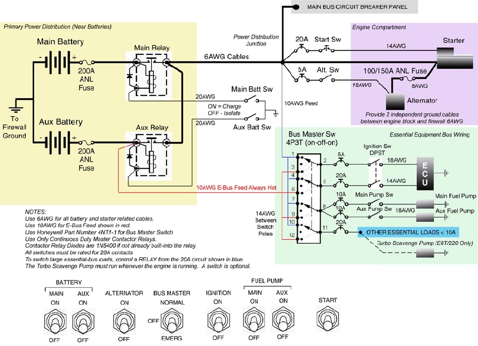
Okay, referring to the abbreviated power distribution diagram
from the Viking installation literature, we see two batteries,
both 'protected' buy current limiters and paralleled onto
the system with independent contactors. One of the two batteries
is fitted with an always hot feeder routed to a 4-pole engine power
selection switch.
Years ago, I proposed a similar two-battery system which
could be automated to some degree with what was at that
time called the Aux Battery Management Module.
http://tinyurl.com/l353p5m
http://tinyurl.com/mrxbrtw
Back in those days, the notion was that at least one of
two electronic ignition systems and perhaps a boost pump
could be supported on an independent battery automatically
isolated from the rest of the airplane when an alternator
failure was detected (low voltage).
Let's revisit those notions in light of the Viking installation
documents that speak to a 'requirement' for a second battery
capable of running the engine for a minimum of 30 minutes.
First, how does one KNOW that battery #2 is capable of
meeting that requirement? It has to be sized -AND- maintained
such that the necessary energy available when needed.
Okay, what conditions would FORCE the use of #2 battery?
(a) no doubt the alternator is off line for what ever
reason and (b) and we KNOW that #1 battery is not capable
of carrying the engine + other endurance loads for at least
30 minutes.
Hmmmm . . . if we KNOW that #1 battery is overtaxed for
the task of supplied combined energy needs but that
#1 plus #2 battery WILL rise to the occasion, then what
is the value in having two batteries? Would a single
battery with a KNOWN capacity for the combined loads not
be a simpler, lighter and lower cost choice?
In other words, what combination of conditions pose such
risk that a second battery is needed to mitigate the risk?
Two batteries DOUBLES your battery maintenance expenses
and adds empty weight . . . all intended to mitigate a
rather rare event . . . alternator failure.
This line of reasoning is germane to the discussions
we were having on Fred's Exp-Bus integration which prompted
the crafting of Figure Z-7. It also applies to Les's question
about diodes suitable for battery isolation. Obviously, the
golden solution will include some assessment of loads over and
above those required to run the engine . . . along with
some decisions as to whether you're expecting to keep the panel all lit
up . . . or have crafted a plan-B that matches your skills
and confidence levels for getting down with a bare minimum
of panel equipment combined perhaps with flight bag back-up
hardware.
If Figure Z-7 were substituted for the figure above, are
there any unforeseen risks? Comments on the Viking drawing,
Figure Z-7 and perceptions of your individual FMEAs are solicited . . .
Bob . . .
| | - The Matronics AeroElectric-List Email Forum - | | | Use the List Feature Navigator to browse the many List utilities available such as the Email Subscriptions page, Archive Search & Download, 7-Day Browse, Chat, FAQ, Photoshare, and much more:
http://www.matronics.com/Navigator?AeroElectric-List |
|
| Description: |
|
| Filesize: |
323.18 KB |
| Viewed: |
8790 Time(s) |
|
|
|
| Back to top |
|
|
teblejw
Joined: 19 Nov 2013
Posts: 14
|
| Posted: Sat Jan 04, 2014 10:20 am Post subject: Viking engine duel battery setup |
|
|
Bob,

As someone who has a Viking engine and who has been looking to modify Z-7 for my electrical system, I'm very interested in this thread.  First, where did you get the diagram at the top of your last posting?  It's clearly different then the one sent by Les Goldner, which I also got from the Viking website.  It appears to be a system for Vikings unreleased turbo version.

I hesitate to make the following comment, since you chose not to answer my last question about alternators running without batteries; but you asked for comments on Z-7 for this application.  Viking claims that the alternator can run with the batteries disconnected and I believe that the diagram provided by Les allows for that.  Your comment in an earlier thread that you wouldn't switch off the battery/batteries unless you were also disconnecting the alternator is a strong position.  I understand that batteries that are properly maintained don't usually fail in a catastrophic manner, but is that never?  Can we quantify?  Hard to separate failures due to inadequate maintenance and others.  In the absence of numbers but anecdotal experiences of failures (mine for one), why not have an allowance for running off the alternator only?  Seems prudent to me, so I'd like to understand why it isn't to you.  Thanks.

Tom


Sent from my iPad


On Jan 4, 2014, at 9:13 AM, "Robert L. Nuckolls, III" <nuckolls.bob(at)aeroelectric.com (nuckolls.bob(at)aeroelectric.com)> wrote:

[quote]  <a6a5924.jpg>


 Okay, referring to the abbreviated power distribution diagram

 from the Viking installation literature, we see two batteries,

 both 'protected' buy current limiters and paralleled onto

 the system with independent contactors. One of the two batteries

 is fitted with an always hot feeder routed to a 4-pole engine power

 selection switch.


 Years ago, I proposed a similar two-battery system which

 could be automated to some degree with what was at that

 time called the Aux Battery Management Module.


  http://tinyurl.com/l353p5m


  http://tinyurl.com/mrxbrtw


 Back in those days, the notion was that at least one of

 two electronic ignition systems and perhaps a boost pump

 could be supported on an independent battery automatically

 isolated from the rest of the airplane when an alternator

 failure was detected (low voltage).


 Let's revisit those notions in light of the Viking installation

 documents that speak to a 'requirement' for a second battery

 capable of running the engine for a minimum of 30 minutes.


 First, how does one KNOW that battery #2 is capable of

 meeting that requirement? It has to be sized -AND- maintained

 such that the necessary energy available when needed.


 Okay, what conditions would FORCE the use of #2 battery?

 (a) no doubt the alternator is off line for what ever

 reason and (b) and we KNOW that #1 battery is not capable

 of carrying the engine + other endurance loads for at least

 30 minutes.


 Hmmmm . . . if we KNOW that #1 battery is overtaxed for

 the task of supplied combined energy needs but that

 #1 plus #2 battery WILL rise to the occasion, then what

 is the value in having two batteries? Would a single

 battery with a KNOWN capacity for the combined loads not

 be a simpler, lighter and lower cost choice?


 In other words, what combination of conditions pose such

 risk that a second battery is needed to mitigate the risk?

 Two batteries DOUBLES your battery maintenance expenses

 and adds empty weight . . . all intended to mitigate a

 rather rare event . . . alternator failure.


 This line of reasoning is germane to the discussions

 we were having on Fred's Exp-Bus integration which prompted

 the crafting of Figure Z-7. It also applies to Les's question

 about diodes suitable for battery isolation. Obviously, the

 golden solution will include some assessment of loads over and

 above those required to run the engine . . . along with

 some decisions as to whether you're expecting to keep the panel all lit

 up . . . or have crafted a plan-B that matches your skills

 and confidence levels for getting down with a bare minimum

 of panel equipment combined perhaps with flight bag back-up

 hardware.


 If Figure Z-7 were substituted for the figure above, are

 there any unforeseen risks? Comments on the Viking drawing,

 Figure Z-7 and perceptions of your individual FMEAs are solicited . . .


   Bob . . .

[b]
| | - The Matronics AeroElectric-List Email Forum - | | | Use the List Feature Navigator to browse the many List utilities available such as the Email Subscriptions page, Archive Search & Download, 7-Day Browse, Chat, FAQ, Photoshare, and much more:
http://www.matronics.com/Navigator?AeroElectric-List |
|
|
|
| Back to top |
|
|
nuckolls.bob(at)aeroelect
Guest
|
| Posted: Sat Jan 04, 2014 3:28 pm Post subject: Viking engine duel battery setup |
|
|
At 12:19 PM 1/4/2014, you wrote:

Bob,


As someone who has a Viking engine and who has been looking to modify

Z-7 for my electrical system, I'm very interested in this

thread.  First, where did you get the diagram at the top of your last

posting?  It's clearly different then the one sent by Les Goldner,

which I also got from the Viking website.  It appears to be a system

for Vikings unreleased turbo version.


    I got it from the Viking website using a link forwarded to

    me by one of the list readers. The exact version is insignificant

    at the moment as the points to ponder deal with the rationale for

    two batteries as opposed to one.


I hesitate to make the following comment, since you chose not to

answer my last question about alternators running without batteries;

but you asked for comments on Z-7 for this application.


    My apologies . . . didn't mean to ignore your question.

    Never hesitate to jump right in the middle of my

    lap if you believe some important link of communication

    has broken. This list isn't about feelings, it's

    about ideas . . . and even though GMCJetpilot found the

    assertion incredible, I cannot be insulted and I welcome

    logical persuasion.


Viking claims that the alternator can run with the batteries

disconnected and I believe that the diagram provided by Les allows for that.


    Okay, that doesn't surprise me. I'm wondering to what extent

    that operating mode has been tested.


Your comment in an earlier thread that you wouldn't switch off the

battery/batteries unless you were also disconnecting the alternator

is a strong position.


     . . . yes . . . based on the legacy design goals

     of yesteryear when the split-rocker master switch

     was king.


     But that was several generations ago in both alternator

     and battery design. Odds are that most airplanes will continue

     operating sans battery . . . but I suspect there are

     limits that should be explored. I had some plans to

     acquire a variable speed drive stand some years ago.

     The goal was to explore the new alternator-only

     paradigm.

I understand that batteries that are properly maintained don't

usually fail in a catastrophic manner, but is that never?  Can we quantify?


    I'll have to ask Skip about that. Concorde has done

    countless failure analysis over the course of battery

    evolution in aircraft and can probably offer us some

    quantitative assessment.


Hard to separate failures due to inadequate maintenance and

others.  In the absence of numbers but anecdotal experiences of

failures (mine for one), why not have an allowance for running off

the alternator only?  Seems prudent to me, so I'd like to understand

why it isn't to you.  Thanks.


     I absolutely agree. But just as I was loath to

     RECOMMEND the internally regulated alternator some

     years back, my reluctance is not based on hard

     negative data but a lack of hard positive data.


     If Viking says they can run alternator only, I

     rather suspect that they have at least determined

     that the engine doesn't quit and the panel stays

     lit with the batteries OFF. I wonder to what extent

     any testing has been accomplished and documented upon

     which a gray beard stuck in such traditions

     can offer confident recommendation.


     Thanks for asking . . .

     Bob . . .
| | - The Matronics AeroElectric-List Email Forum - | | | Use the List Feature Navigator to browse the many List utilities available such as the Email Subscriptions page, Archive Search & Download, 7-Day Browse, Chat, FAQ, Photoshare, and much more:
http://www.matronics.com/Navigator?AeroElectric-List |
|
|
|
| Back to top |
|
|
kearney
Joined: 20 Sep 2008
Posts: 563
|
| Posted: Sat Jan 04, 2014 5:49 pm Post subject: Viking engine duel battery setup |
|
|
Hi All

This is the Eggenfellner Aircraft Engines wiring diagram for a Subaru engine (turbo'd). This where the E6T engine reference comes from.

Cheers

Les


Sent from my iPhone


On Jan 4, 2014, at 9:13 AM, "Robert L. Nuckolls, III" <nuckolls.bob(at)aeroelectric.com (nuckolls.bob(at)aeroelectric.com)> wrote:

[quote]  <a6a5924.jpg>


 Okay, referring to the abbreviated power distribution diagram

 from the Viking installation literature, we see two batteries,

 both 'protected' buy current limiters and paralleled onto

 the system with independent contactors. One of the two batteries

 is fitted with an always hot feeder routed to a 4-pole engine power

 selection switch.


 Years ago, I proposed a similar two-battery system which

 could be automated to some degree with what was at that

 time called the Aux Battery Management Module.


  http://tinyurl.com/l353p5m


  http://tinyurl.com/mrxbrtw


 Back in those days, the notion was that at least one of

 two electronic ignition systems and perhaps a boost pump

 could be supported on an independent battery automatically

 isolated from the rest of the airplane when an alternator

 failure was detected (low voltage).


 Let's revisit those notions in light of the Viking installation

 documents that speak to a 'requirement' for a second battery

 capable of running the engine for a minimum of 30 minutes.


 First, how does one KNOW that battery #2 is capable of

 meeting that requirement? It has to be sized -AND- maintained

 such that the necessary energy available when needed.


 Okay, what conditions would FORCE the use of #2 battery?

 (a) no doubt the alternator is off line for what ever

 reason and (b) and we KNOW that #1 battery is not capable

 of carrying the engine + other endurance loads for at least

 30 minutes.


 Hmmmm . . . if we KNOW that #1 battery is overtaxed for

 the task of supplied combined energy needs but that

 #1 plus #2 battery WILL rise to the occasion, then what

 is the value in having two batteries? Would a single

 battery with a KNOWN capacity for the combined loads not

 be a simpler, lighter and lower cost choice?


 In other words, what combination of conditions pose such

 risk that a second battery is needed to mitigate the risk?

 Two batteries DOUBLES your battery maintenance expenses

 and adds empty weight . . . all intended to mitigate a

 rather rare event . . . alternator failure.


 This line of reasoning is germane to the discussions

 we were having on Fred's Exp-Bus integration which prompted

 the crafting of Figure Z-7. It also applies to Les's question

 about diodes suitable for battery isolation. Obviously, the

 golden solution will include some assessment of loads over and

 above those required to run the engine . . . along with

 some decisions as to whether you're expecting to keep the panel all lit

 up . . . or have crafted a plan-B that matches your skills

 and confidence levels for getting down with a bare minimum

 of panel equipment combined perhaps with flight bag back-up

 hardware.


 If Figure Z-7 were substituted for the figure above, are

 there any unforeseen risks? Comments on the Viking drawing,

 Figure Z-7 and perceptions of your individual FMEAs are solicited . . .


   Bob . . .

[b]
| | - The Matronics AeroElectric-List Email Forum - | | | Use the List Feature Navigator to browse the many List utilities available such as the Email Subscriptions page, Archive Search & Download, 7-Day Browse, Chat, FAQ, Photoshare, and much more:
http://www.matronics.com/Navigator?AeroElectric-List |
|
|
|
| Back to top |
|
|
jluckey(at)pacbell.net
Guest
|
| Posted: Sun Jan 05, 2014 10:49 am Post subject: Viking engine duel battery setup |
|
|
It occurs to me that this topic gets pretty design-specific in a hurry and without specifying a design, this will turn into an exercise in arm waving.
Therefore, I have included some general comments sprinkled among Bob's remarks, below.
-Jeff From: "Robert L. Nuckolls, III" <nuckolls.bob(at)aeroelectric.com>
To: aeroelectric-list(at)matronics.com
Sent: Saturday, January 4, 2014 5:15 AM
Subject: Re: Viking engine duel battery setup
--> AeroElectric-List message posted by: "Robert L. Nuckolls, III" <nuckolls.bob(at)aeroelectric.com (nuckolls.bob(at)aeroelectric.com)>
At 01:49 PM 1/3/2014, you wrote:
| Quote: | for many of the same reasons that (I imagine) you put a "buss tie" contactor in the Z-14 drawings.
|
But what might those reasons be? In other words, we
add a component to a system to effect some desired
functionality that figures into the overall performance,
failure tolerance and risks.
If diodes were incorporated in the manner suggested
to feed the two batteries, how would we expect these
to operate and for what purpose?
The diodes are to isolate the batteries and their systems from each other. If you simple run a wire from the alternator B terminal to batt A and then to batt B you have paralleled the batteries when your intent was only to charge them. It could be an unintended side-effect. If your mission is to charge the batts then make sure your circuit does that. If your mission is to parallel the batts then do that, but don't let one just happen as a side effect of the other.
I'm not trying to be obtuse here my friend. I
AM encouraging all of my readers to understand
the application of every component they choose
to add to their system. Suppose I offered a description
for the buss-tie contactor like, "This contactor
offers pilot control of the phramistat to prevent
inadvertent operation of the whatsadozit and
potential damage to the dingusfuzzy."
The inquiring builder would probably want some
detailed expansion on that statement . . . un-
fortunately, others will assume the statement
correct and useful based on the reputation
(deserved or otherwise) of the writer.
It is difficult to control the assumptions made by readers.
I encourage yourself and others to KNOW why
a part is included and UNDERSTAND what useful
things it will do for you. Hence my question
as to any value you perceive for having those
diodes in place as suggested.
I know why - been there done that - and repaired the damage from some of those uninnd Get Some AWESOME FREE rget="_blank" href="http://www.aeroelectric.com/">www.aeroelectric.comwww.mypilots; &nb========================
| | - The Matronics AeroElectric-List Email Forum - | | | Use the List Feature Navigator to browse the many List utilities available such as the Email Subscriptions page, Archive Search & Download, 7-Day Browse, Chat, FAQ, Photoshare, and much more:
http://www.matronics.com/Navigator?AeroElectric-List |
|
|
|
| Back to top |
|
|
nuckolls.bob(at)aeroelect
Guest
|
| Posted: Sun Jan 05, 2014 12:51 pm Post subject: Viking engine duel battery setup |
|
|
| Quote: |
If diodes were incorporated in the manner suggested
to feed the two batteries, how would we expect these
to operate and for what purpose?
The diodes are to isolate the batteries and their systems from each other. If you simple run a wire from the alternator B terminal to batt A and then to batt B you have paralleled the batteries when your intent was only to charge them. It could be an unintended side-effect. If your mission is to charge the batts then make sure your circuit does that. If your mission is to parallel the batts then do that, but don't let one just happen as a side effect of the other. |
Agreed. I can deduce no practical purpose for
these diodes. As long as the alternator is
operating normally, it charges both batteries.
If alternator fails, you get a low-voltage
warning light and you then separate the
batteries onto their respective tasks.
In other words, the system can service as many
batteries in parallel as dictated by the
alternator-out operating conditions. Simply
parallel through hard contacts for normal ops;
separate for alternator-out ops.
A 'dead' battery will not accept 'charge' from
a fully charged battery. If the batteries are
remarkably different in size, the smaller one
might want to be OFF during cranking.
Bob . . . [quote][b]
| | - The Matronics AeroElectric-List Email Forum - | | | Use the List Feature Navigator to browse the many List utilities available such as the Email Subscriptions page, Archive Search & Download, 7-Day Browse, Chat, FAQ, Photoshare, and much more:
http://www.matronics.com/Navigator?AeroElectric-List |
|
|
|
| Back to top |
|
|
|
|
You cannot post new topics in this forum
You cannot reply to topics in this forum
You cannot edit your posts in this forum
You cannot delete your posts in this forum
You cannot vote in polls in this forum
You cannot attach files in this forum
You can download files in this forum
|
Powered by phpBB © 2001, 2005 phpBB Group
|

