 |
Matronics Email Lists
Web Forum Interface to the Matronics Email Lists
|
| View previous topic :: View next topic |
| Author |
Message |
nuckolls.bob(at)aeroelect
Guest
|
 Posted: Sun Jan 05, 2014 10:32 am Post subject: Wiring Verification Posted: Sun Jan 05, 2014 10:32 am Post subject: Wiring Verification |
 |
|
Hi Bob,
I attended one of your seminars in Nashville, TN some years ago as well as purchased a second updated copy of your book which I refer to often. However, not being an electrical engineer, I'd like to verify my wing rewiring plan for my 12 volt all metal Luscombe if possible.
Hi Ron . . . it's been some time! I'm sure we can sort
out your concerns . . .
The wing run is approximately 16 feet to the wing root from the wing tip, 14 feet from the landing light to wing root, and another 6+ feet to the switches on each side from the wing root. I plan to install a disconnect of some sort at each wing root to allow for an uncomplicated removal of the wing. Also, by the way, I will be installing a Plane Power Alternator and a B&C Starter in this rebuild if that should make any difference.
I am wiring an Aeroflash power supply, (1.8 amp-23.4 watts) in each wingtip . . .
Okay, a power wire coming in from each load to join at the
panel switch for STROBES. 4A total load with half carried
by the individual wires. I would recommend 20AWG for these
conductors . . . not so much for electrical capability but
for mechanical robustness. The difference in weight has
no demonstrable down-side . . .
piggybacking onto my 26 watt Whelen position lights,
. . . again, 20AWG conductors to each fixture brought
all the way to the POSITION LTS switch.
and a 100 watt landing light in each wing.
These are about 8A each. Is one adjusted for taxi illumination
with the other directed for landing?
Suggest 16AWG wire to each fixture. Control each with
its own switch.
I plan to switch to LED landing lights in the future but not anytime soon. My plan is to run three wires adjacent to one another up to the landing light where they will divide and separate. They will not run in a conduit but will run bundled only by a periodic small wedge clamp through the wing leading edge. I am utilizing Tefzel 22759 wire.
Use the same wires and switches for the LED fixtures.
There is no sin in having wires that are 'too heavy' . . .
only in having wires that are 'too light'.
I have determined the plan through my mathmatical calculations utilizing your book. To be on the safe side, I expect to be using a 16 gauge wire for my power supply and position lights and a 14 gauge wire for my landing lights. None of these wires are to be shielded at this point. Aeroflash indicated that if the power supply was mounted in the wing tip, it was unnecessary to utilize a shielded wire in the run. I do not know if I need shielding on the landing lights and need your advice.
The 20AWG wire is 10 milliohms per foot. Your proposed
20-foot runs to the nav and strobe lights offers a
.010 x 20 x 2 = .4 volt drop in each segment for
3% in your 14-volt system. Entirely within practical guidelines.
Going the next step larger in wire would only drop your
losses by 40% of 3% to just under 2% . . . an unobservable
difference.
16AWG on the landing lights is more like 0.004 x 20 x
8 for a drop of 0.64 volts or 4.5% . . . again
quite within limits for legacy design goals of 5%
max loss in wiring. Of course, that will become
a non-issue with the LED upgrade.
Let me also indicate that I am in the group who wants to get it correct the first time so I am seeking qualified advice prior to pulling the wire. If possible, please advise your recommendations or if my plan is solid. Also, what sort of disconnect would you install at each wing root?
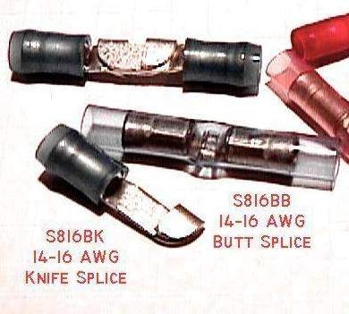
Do you plan to remove the wings often? The most robust
service connections are knife splices covered in heat-
shrink. Given the small number of wires, I'd personally
go that route.
[img]cid:.0[/img]
I may have other wiring questions and will be happy to pay for this service.
Not necessary. Let's carry out the conversation here
on the List for sharing . . .
Wishing you the very best in 2014 and thanking you in advance for your reply, I remain,
You too my friend! Nice airplane by the way . . . got
a lot of time in a 120+ (electrical system added)
flying Young Eagles. Real blast . . .
Bob . . .
| | - The Matronics AeroElectric-List Email Forum - | | | Use the List Feature Navigator to browse the many List utilities available such as the Email Subscriptions page, Archive Search & Download, 7-Day Browse, Chat, FAQ, Photoshare, and much more:
http://www.matronics.com/Navigator?AeroElectric-List |
|
| Description: |
|
| Filesize: |
80.54 KB |
| Viewed: |
1244 Time(s) |
|
|
|
| Back to top |
|
 |
nuckolls.bob(at)aeroelect
Guest
|
| Posted: Sun Jan 05, 2014 3:26 pm Post subject: Wiring Verification |
|
|
At 03:47 PM 1/5/2014, you wrote:

Bob,


Thanks for your consideration and kind reply.


I was figuring a total of 24 feet of wire run for the wing tip lamps

and power supply to the switch including the disconnect at the wing

root, and a 20 foot run for the landing lights including the

disconnect at the wing root.  Perhaps I was vague on this measurement

and did not explain it very well or perhaps the wires don't add

together for the total drop.  I confess my knowledge about wiring is

lacking in general although I am attempting to come up to speed with

respect to this task at hand.  I neglected to include both runs

together for the total of .8 volt drop.  However using the 24 foot

run, I come up with .96 volt or near 1 volt.  Divided by a 13 volt

system, I read that as .076 or beyond the 5% legacy.  The Aeroflash

documentation suggested the use of  an 18 AWG but I'm not aware of

what wire length run was used for the calculation.  Luscombes have a

35 foot wingspan.  So I figured a 16 gauge would include my margin of error.


   If this is a metal airplane, grounding the devices locally

   provides a much lower ground path resistance . . . essentially

   negligible . . .


I do not plan on removing the wings often, perhaps not at all,

however, I'd like to provide for it now to eliminate a random cutting

when it occurs, because it will occur.  In looking at the old

Luscombe documentation, initially some sort of junction block was

located at each wing root but those connections have long ago been

changed when the wings were swapped out.


   If you can wire it up without junctions, so much the

   better. Just put a service loop of wire at the wing

   root . . . 3-4 inches in diameter. This will offer

   'slack' from which future splices can be implemented

   should it become necessary.


I was thinking of a using a triple Seal-All type conductor for the

disconnect at the wing root but hadn't considered the knife

splices.  Actually, to my knowledge, I have never employed a knife

splice in any of my wiring.


   The ideal configuration is no connector at all. Once

   you break the wires, putting them back together is

   pretty much a toss-up. Cessna started using Mate=n=Lok

   plastic connectors at the root and other locations

   as a production aid back about 1967. The car-guys have

   been doing it too for decades. Risks are low no matter

   what technology you choose.


This leading edge location is very tight also providing for the

aileron control cables and fuel lines coming in through the leading

edge with a pulley positioned right at the juncture of the leading

edge carrying the control cables.  So, I anticipated bringing the

three wires into the fuselage through the leading edge and securing

on the last wing root rib and positioning my disconnect at that

location.  The wires would then reconnect through the splice and

continue on through and around the front door upright and down to the

rear of the instrument panel.


You did not mention anything about shielded wiring.    Would the

total wire runs as I have listed above adjust your recommendations on

the wire sizing?


   None of those wires would benefit from shielding.


When I purchased radios I also purchased a wiring harness to connect

to my buss and fuses or switches as appropriate.  Hopefully, that

will be more straight forward but I'm sure I'll have questions there.


   No problem . . . that's what we're here for . . .


Thanks again for your reply on this cold winter afternoon in Kansas.


   You got that right. It was about 4F when I got up

   this morning . . . supposed to get down to 0F

   tonight. But looking at the nation-wind chill-indexes,

   we've got it easy.

   Bob . . .
| | - The Matronics AeroElectric-List Email Forum - | | | Use the List Feature Navigator to browse the many List utilities available such as the Email Subscriptions page, Archive Search & Download, 7-Day Browse, Chat, FAQ, Photoshare, and much more:
http://www.matronics.com/Navigator?AeroElectric-List |
|
|
|
| Back to top |
|
|
|
|
You cannot post new topics in this forum
You cannot reply to topics in this forum
You cannot edit your posts in this forum
You cannot delete your posts in this forum
You cannot vote in polls in this forum
You cannot attach files in this forum
You can download files in this forum
|
Powered by phpBB © 2001, 2005 phpBB Group
|

