 |
Matronics Email Lists
Web Forum Interface to the Matronics Email Lists
|
| View previous topic :: View next topic |
| Author |
Message |
Fred Klein
Joined: 26 Mar 2012
Posts: 503
|
 Posted: Sat Jan 18, 2014 7:59 pm Post subject: Ammeters & Voltmeters Posted: Sat Jan 18, 2014 7:59 pm Post subject: Ammeters & Voltmeters |
 |
|
After reading Bud's post a few moments ago, I have a couple of general questions about ammeters and voltmeters which perhaps an expert can answer for me.


Up til now, I've planned to measure the voltage at the plus side of the battery...Is that the best place to measure?...or are there multiple places where voltage should be measured?...and how is that accomplished?...with a rotary switch?


Similarly, I've planned to place my ammeter in series on the output side of the alternator...will that do?...or again, are there multiple places where amperage should be measured?...and if so, where?...and how is that generally accomplished?...with a rotary switch?


(I have the EXP 2 Bus by Control Vision along w/ their indicator module; however, the word I'm getting from others is that the warning lights on the module are not to be trusted, and that led to my purchasing a delightful little pair of Mitchell instruments.)


Fred
| | - The Matronics Europa-List Email Forum - | | | Use the List Feature Navigator to browse the many List utilities available such as the Email Subscriptions page, Archive Search & Download, 7-Day Browse, Chat, FAQ, Photoshare, and much more:
http://www.matronics.com/Navigator?Europa-List |
|
|
|
| Back to top |
|
 |
alanb(at)dpy01.co.uk
Guest
|
| Posted: Sun Jan 19, 2014 2:11 am Post subject: Ammeters & Voltmeters |
|
|
Personally I will be putting a voltmeter on the battery side.
That will give me the charge voltage when the alternator is running and the state of the battery when it is not. Not contemplating an ammeter.
Alan
Sent from my iPad
| Quote: | On 19 Jan 2014, at 03:56, Fred Klein <fklein(at)orcasonline.com> wrote:
After reading Bud's post a few moments ago, I have a couple of general questions about ammeters and voltmeters which perhaps an expert can answer for me.
Up til now, I've planned to measure the voltage at the plus side of the battery...Is that the best place to measure?...or are there multiple places where voltage should be measured?...and how is that accomplished?...with a rotary switch?
Similarly, I've planned to place my ammeter in series on the output side of the alternator...will that do?...or again, are there multiple places where amperage should be measured?...and if so, where?...and how is that generally accomplished?...with a rotary switch?
(I have the EXP 2 Bus by Control Vision along w/ their indicator module; however, the word I'm getting from others is that the warning lights on the module are not to be trusted, and that led to my purchasing a delightful little pair of Mitchell instruments.)
Fred
|
| | - The Matronics Europa-List Email Forum - | | | Use the List Feature Navigator to browse the many List utilities available such as the Email Subscriptions page, Archive Search & Download, 7-Day Browse, Chat, FAQ, Photoshare, and much more:
http://www.matronics.com/Navigator?Europa-List |
|
|
|
| Back to top |
|
|
frans(at)privatepilots.nl
Guest
|
| Posted: Sun Jan 19, 2014 3:11 am Post subject: Ammeters & Voltmeters |
|
|
-----BEGIN PGP SIGNED MESSAGE-----
Hash: SHA1
On 01/19/2014 04:56 AM, Fred Klein wrote:
| Quote: | Up til now, I've planned to measure the voltage at the plus side
of the battery...Is that the best place to measure?...or are there
multiple places where voltage should be measured?...and how is
that accomplished?...with a rotary switch?
|
Voltage should be the same over the entire system. Unless there is too
much resistance or loose contacts. I would put the voltmeter over the
panel bus, since that voltage is the most interesting during flight. I
wouldn't care too much if the battery contact is loose and the battery
voltage drops, as long as the alternator keeps up the panel voltage,
this failure will only cause problems with the next engine start, and
since you are then on the ground you can do all the trouble shooting.
There is not much else you need to know.
| Quote: | Similarly, I've planned to place my ammeter in series on the
output side of the alternator...will that do?...
|
Depends again on what you want to know. I have the ammeter in the
battery wire. This gives me the following information:
1) During flight the amp reading should be close to zero. This
indicates that the battery is fully charged and not taking current,
and also that apparently the alternator is feeding the electrical
system because no current is taken from the battery. (Directly after
starting I see current going to the battery to compensate the charge
taken out for starting, but it should run down close to zero after a
few minutes. If the battery continues to take current all the time,
this indicates that the battery is not so healthy anymore).
2) On the ground, with the engine off, it is easy to check the health
of the system, because every electrical load will reveal itself on the
ammeter since the battery is now feeding the system. I regularly
perform these tests: I know how much current sub systems are supposed
to consume, I toggle all switches individually and see how much load
is taken, if the value has changed since last time this tells you
something before real problems arise. If, let's say, the fuel pump
normally uses 2 amps but suddenly it consumes 4, it means something is
starting to go wrong with it (internal friction, partly clogged?) and
it can be expected to fail in the near future. ALso, this test,
combined with checking the voltmeter, gives an idication about the
health of the battery. If the voltage sags too much under load this
usually means that the battery is going to need replacement.
| Quote: | places where amperage should be measured?...and if so,
where?...and how is that generally accomplished?...with a rotary
switch?
|
I try to avoid switches. Switches, conbined with their associated
wiring, connectors etc, are failure points. If you start to measure
weird values, it can be that something is wrong with the alternator,
but it can also (more likely?) mean that there is something wrong with
the switch, contacts or wires.
Just keep it simple: measure voltage in the panel, this is where all
sensitive avionics is and thus most important, and also it makes
connecting the voltmeter much easier and failure proof because the
voltage to measure is directly there and no long wires are required.
To measure amps, you need to have a resistor somewhere in the wire. I
prefer to have this directly at the battery because this resistor is
doing the least harm at that place, and if it fails, has the least
impact on your flight. And it gives you the most useful information at
that location. All other information can be derived from what you are
measuring: if the battery provides current it means that the
alternator isn't working properly; you don't have to measure the amps
coming out of the alternator to find out that that it is failing.
Frans
-----BEGIN PGP SIGNATURE-----
Version: GnuPG v2.0.22 (GNU/Linux)
iQIcBAEBAgAGBQJS27IYAAoJEC+zXxqs0ZzVBhsQAL7kvHbiQOFZowSUoALSdZm9
EW+ACyWKjf6BBq3/25BhthH060y61ODJLt0qFqjWA4MjgAFyaAbf8j/TveVzdrcW
dwVkTcdZ7lxVqMn1CxyT1GKBqMnJSI/k1WrLH7grbd/VwqvvrDh0tohdOAPZ9Cda
3bgSV4bVWFYH4eLUqHmBCBP9Pli+ez+wQjy4URuFjG7fiSMo42AjJ1iF4U+K16zV
e4tBtfYynatcIG+mcbZ4U2tUZBHKg9jyHyp+sHf7zSrQIBcx7OLXRQ6M/owZwJ4/
JB150SN8/Qy1QBO2GvVIP8CkuH+dw+RmV0sDv7/XUB6Ok4gSRCttP/ssSVwrJXmj
BeZ/H6cNXxcEy7XPmLeBhY6nnkFE7SwnMIFm+6hQjx3vhbswNBt+fn129GivGqj5
CP7XbpqhtShP2IdDmC/7lLH+tb40034S+qk5JLlQSfWLniJAhqJp0K9y4HmXKFV4
10wTWVelezwuRBdfg9PLHQy/0BHhhhhjrewUUpSYW67iMb4FGVMweideXGRbqdcj
a+OD//i76GFFQdOq5Kj6Q8YIVo25G3SOxi1yxYr1Ych/7ciuDHEgO9cvcPkyePmb
l61M68p5jl96Fk2XrEcd8PANKyVWHzjDfZYwbghS6DGv9Uo6FHQMZnyTEgFzW0b2
CeMAl+Q11eDZwbxhHCLX
=Q5AT
-----END PGP SIGNATURE-----
| | - The Matronics Europa-List Email Forum - | | | Use the List Feature Navigator to browse the many List utilities available such as the Email Subscriptions page, Archive Search & Download, 7-Day Browse, Chat, FAQ, Photoshare, and much more:
http://www.matronics.com/Navigator?Europa-List |
|
|
|
| Back to top |
|
|
Fred Klein
Joined: 26 Mar 2012
Posts: 503
|
| Posted: Sun Jan 19, 2014 8:21 am Post subject: Ammeters & Voltmeters |
|
|
Frans...thank you for your thoughtful reply to my concerns, especially by spelling things out in crayon to a guy who is electronically-challenged...just what I needed, although, when you write:
| Quote: | To measure amps, you need to have a resistor somewhere in the wire. I
prefer to have this directly at the battery because this resistor is
doing the least harm at that place, and if it fails, has the least
impact on your flight. And it gives you the most useful information at
that location.
|
..I must admit that I have no idea WHY a resistor is essential, nor can I imagine what criteria are appropriate for sizing such a resistor, nor do I understand why failure would cause minimal harm if it's located directly at the battery...
All the best,
Fred
| | - The Matronics Europa-List Email Forum - | | | Use the List Feature Navigator to browse the many List utilities available such as the Email Subscriptions page, Archive Search & Download, 7-Day Browse, Chat, FAQ, Photoshare, and much more:
http://www.matronics.com/Navigator?Europa-List |
|
|
|
| Back to top |
|
|
grahamsingleton(at)btinte
Guest
|
| Posted: Sun Jan 19, 2014 8:51 am Post subject: Ammeters & Voltmeters |
|
|
Fred
You can measure current by noting the voltage drop across a short length of
wire, very small drop in the case of the main buss but still measurable.
Then, Amps equals Volts divided by Resistance
Graham
From: Fred Klein <fklein(at)orcasonline.com>
To: europa-list(at)matronics.com
Sent: Sunday, 19 January 2014, 16:20
Subject: Re: Ammeters & Voltmeters
--> Europa-List message posted by: Fred Klein <fklein(at)orcasonline.com (fklein(at)orcasonline.com)>
Frans...thank you for your thoughtful reply to my concerns, especially by spelling things out in crayon to a guy who is electronically-challenged...just what I needed, although, when you write:
| Quote: | To measure amps, you need to have a resistor somewhere in the wire. I
prefer to have this directly at the battery because this resistor is
doing the least harm at that place, and if it fails, has the least
impact on your flight. And it gives you the most useful information at
that location.
|
...I must admit that I have no idea WHY a resistor is essential, nor can I imagine what criteria are appropriate for sizing such a resistor, nor do I understand why failure would cause minimal harm if it's located directly at the battery...
All the best,
[quote][b]
| | - The Matronics Europa-List Email Forum - | | | Use the List Feature Navigator to browse the many List utilities available such as the Email Subscriptions page, Archive Search & Download, 7-Day Browse, Chat, FAQ, Photoshare, and much more:
http://www.matronics.com/Navigator?Europa-List |
|
|
|
| Back to top |
|
|
Fred Klein
Joined: 26 Mar 2012
Posts: 503
|
| Posted: Sun Jan 19, 2014 9:06 am Post subject: Ammeters & Voltmeters |
|
|
On Jan 19, 2014, at 8:48 AM, GRAHAM SINGLETON wrote:
| Quote: | You can measure current by noting the voltage drop across a short length of
wire, very small drop in the case of the main buss but still measurable.
Then, Amps equals Volts divided by Resistance
|
Graham...OK...but doesn't that all happen within the amp meter?...if I understand Frans correctly, he's calling for the addition of a resistor in the line back at the battery...(?)...Fred
[quote][b]
| | - The Matronics Europa-List Email Forum - | | | Use the List Feature Navigator to browse the many List utilities available such as the Email Subscriptions page, Archive Search & Download, 7-Day Browse, Chat, FAQ, Photoshare, and much more:
http://www.matronics.com/Navigator?Europa-List |
|
|
|
| Back to top |
|
|
grahamsingleton(at)btinte
Guest
|
| Posted: Sun Jan 19, 2014 9:20 am Post subject: Ammeters & Voltmeters |
|
|
Yes, it can do. But I don't quite understand Frans' remark that there's no problem if the resistor fails.
If that happened you would have no power?
Graham
From: Fred Klein <fklein(at)orcasonline.com>
To: europa-list(at)matronics.com
Sent: Sunday, 19 January 2014, 17:05
Subject: Re: Europa-List: Ammeters & Voltmeters
On Jan 19, 2014, at 8:48 AM, GRAHAM SINGLETON wrote:
| Quote: | You can measure current by noting the voltage drop across a short length of
wire, very small drop in the case of the main buss but still measurable.
Then, Amps equals Volts divided by Resistance
|
Graham...OK...but doesn't that all happen within the amp meter?...if I understand Frans correctly, he's calling for the addition of a resistor in the line back at the battery...(?)...Fred
=3D=3D=3D=3D=3D=3D=3D=3D=3D=3D=3D=3D=3D=3D=3D=3D=3D=3D=3D=3D=3D=3D=3D=3D=3D=3D=3D=3D=3D=3D=3D=3D=3D=3D=3D=3D=3D=3D=3D=3D=3D=3D=3D=3D=3D=3D=3D=3D=3D=3D=3D=3D=3D=3D=3D=3D=3D=3D=3D=3D=3D=3D=3D=3D=3D=3D=3D=3D=3D=3D=3D=3D=3D=3D=3D=3D=3D=3D=3D=3D=3D=3D=3D=3D=3D=3D=3D=3D=3D=3D=3D=3D=3D=3D=3D=3D=3D=3D=3D=3D=3D=3D=3D=3D=3D=3D=3D=3D=3D=3D=3D=3D=3D=3D=3D=3D=3D=3D=3D=3D=3D=3D=3D=3D=3D=3D=3D=3D=3D=3D=3D=3D=3D=3D=3D=3D=3D=3D=3D=3D=3D=3D=3D=3D=3D=3D=3D=3D=3D=3D3D=3D=3D=3D=3D=3D=3D=3D=3D=3D=3D=3D=3D=3D=3D=3D=3D=3D=3D=3D=3D=3D=3D=3D=3D=3D=3D=3D=3D=3D=3D=3D=3D=3D=3D=3D=3D=3D=3D=3D=3D=3D=3D=3D=3D=3D=3D=3D=3D=3D=3D=3D [/b][b]
| | - The Matronics Europa-List Email Forum - | | | Use the List Feature Navigator to browse the many List utilities available such as the Email Subscriptions page, Archive Search & Download, 7-Day Browse, Chat, FAQ, Photoshare, and much more:
http://www.matronics.com/Navigator?Europa-List |
|
|
|
| Back to top |
|
|
richard.holder(at)outlook
Guest
|
| Posted: Sun Jan 19, 2014 9:24 am Post subject: Ammeters & Voltmeters |
|
|
| Quote: | After reading Bud's post a few moments ago, I have a
couple of general questions about ammeters and
voltmeters which perhaps an expert can answer for me.
|
| Quote: | Up til now, I've planned to measure the voltage at the
plus side of the battery...Is that the best place to
measure?...or are there multiple places where voltage
should be measured?...and how is that
accomplished?...with a rotary switch?
|
| Quote: | Similarly, I've planned to place my ammeter in series
on the output side of the alternator...will that
do?...or again, are there multiple places where
amperage should be measured?...and if so, where?...and
how is that generally accomplished?...with a rotary
switch?
|
| Quote: | (I have the EXP 2 Bus by Control Vision along w/ their
indicator module; however, the word I'm getting from
others is that the warning lights on the module are not
to be trusted, and that led to my purchasing a
delightful little pair of Mitchell instruments.)
|
In certified planes the amps are sometimes measured out of
the alternator regulator (plus scale only) or in/out of
the battery (plus and minus scale)
The latter is more useful but often is not the case
Voltmeters are damped so they don't move violently.
Ammeters aren't (mine anyway - analogue not digital) and
can change rapidly. Tha is why i knew that all four Ducati
replacments I tried after my first one died at 175 hours
were not working the way I would want - a 5 cycle per sec
oscillation between 2 and 10 amps - which would have also
been the volts oscillating between probabaly 13.5 and 15
volts.
With only a voltmeter I would have been unaware of this
(maybe that would have been better).
I found the Schicke recifier/regulator and it has been
perfectly normal ever since with no oscillations.
And that word "oscillations" is a hint why you should NOT
put an ammeter in the line between the stator and the RR.
The stator produces AC voltage and therefore current so
the ammeter would read zero unless you had an AC ammeter !
I measured up to 30 v AC coming out of the stator at full
welly.
This all means that I would always have an ammeter AND a
voltmeter. On;y with both can you be sure of what is
happening. The voltmeter can be digital, but an analogue
ammeter is the best way.
In terms of this resistor, you can either put the whole
current through an ammeter (made to suit) in which case
the current is measured across a small value resistor
inside; or the small resistor (known as a "shunt") can be
fixed in the cable and the ammeter measures across it.
This "shunt" way avoids long runs of cable into the panel
taking the whole current (with Rotax is it not much - max
19 A)
HIR (Hope I'm Right !)
Richard Holder
G-OWWW
| | - The Matronics Europa-List Email Forum - | | | Use the List Feature Navigator to browse the many List utilities available such as the Email Subscriptions page, Archive Search & Download, 7-Day Browse, Chat, FAQ, Photoshare, and much more:
http://www.matronics.com/Navigator?Europa-List |
|
|
|
| Back to top |
|
|
gholland(at)content-strea
Guest
|
| Posted: Sun Jan 19, 2014 9:25 am Post subject: Ammeters & Voltmeters |
|
|
The majority of ammeters are connected in series and have a shunt resistor connected in series too.

Since the ammeter [url=http://en.wikipedia.org/wiki/Shunt_(electrical)#Use_in_current_measuring]shunt[/url] has a very low resistance, wiring the ammeter in parallel with a voltage source will cause a short circuit, at best blowing a fuse, possibly damaging the instrument and wiring.

In short an external or internal shunt is required when fitting an Ammeter. Is this what Frans refers too?

Gerry

 [quote][b]
| | - The Matronics Europa-List Email Forum - | | | Use the List Feature Navigator to browse the many List utilities available such as the Email Subscriptions page, Archive Search & Download, 7-Day Browse, Chat, FAQ, Photoshare, and much more:
http://www.matronics.com/Navigator?Europa-List |
|
|
|
| Back to top |
|
|
budyerly(at)msn.com
Guest
|
| Posted: Sun Jan 19, 2014 11:13 am Post subject: Ammeters & Voltmeters |
|
|
Fred,

Sorry to confuse you.  Volt Meters and Ammeters are best installed as charge meters, in my opinion, (alternator on the first post of the shunt and the Battery input on the other).  This is complicated by the EXP (or simplified) by simply putting the ALT lead and Bat leads on the respective posts.  Of course the Control Vision Folks have a diagram on how we non pros should install the EXP for a Rotax.  However, I find that the Rotax regulator tends to run high due to the PTC S2 terminal internal resistance.  This drives the Regulator to increase voltage, if the voltage exceeds about 14.5 then the OVP circuit kills the S2 power as the system senses an over-volt
| | - The Matronics Europa-List Email Forum - | | | Use the List Feature Navigator to browse the many List utilities available such as the Email Subscriptions page, Archive Search & Download, 7-Day Browse, Chat, FAQ, Photoshare, and much more:
http://www.matronics.com/Navigator?Europa-List |
|
|
|
| Back to top |
|
|
Fred Klein
Joined: 26 Mar 2012
Posts: 503
|
| Posted: Sun Jan 19, 2014 12:06 pm Post subject: Ammeters & Voltmeters |
|
|
On Jan 19, 2014, at 11:13 AM, Bud Yerly wrote:
| Quote: | | Sorry to confuse you. |
Bud...not at all...your posts are always informative, and as long as questions raised are not considered stupid questions, it's all good.
Recall that my powerplant is a Subaru derivative, so don't trouble yourself w/ Rotax-related issues on my behalf.
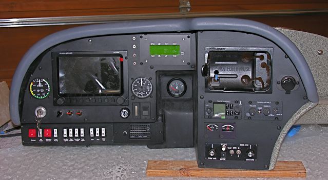
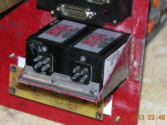
I thought it wise to supplement the voltage/amperage warning lights in the EXP 2 Bus Indicator Module with separate meters from Mitchell...pixs below.
Cheers,
Fred
[img]cid:EB8FD23F-6009-4CDF-AE89-B379D3A9C249[/img]
[img]cid:F4713640-3F20-4638-A09A-E5A9CC567D2C[/img]
| | - The Matronics Europa-List Email Forum - | | | Use the List Feature Navigator to browse the many List utilities available such as the Email Subscriptions page, Archive Search & Download, 7-Day Browse, Chat, FAQ, Photoshare, and much more:
http://www.matronics.com/Navigator?Europa-List |
|
| Description: |
|
| Filesize: |
50.81 KB |
| Viewed: |
11798 Time(s) |
|
| Description: |
|
| Filesize: |
61.87 KB |
| Viewed: |
11798 Time(s) |
|
|
|
| Back to top |
|
|
budyerly(at)msn.com
Guest
|
| Posted: Sun Jan 19, 2014 3:56 pm Post subject: Ammeters & Voltmeters |
|
|
Fred,
I should have remembered. I used the Subi E85 with the EXP and a standard belt driven Denso automotive alternator and hooked it up per the book. Never had an electrical problem.
Your EXP should work like a champ with an automotive alternator.
Regards,
Bud
From: fklein(at)orcasonline.com
Subject: Re: Ammeters & Voltmeters
Date: Sun, 19 Jan 2014 12:05:49 -0800
To: europa-list(at)matronics.com
On Jan 19, 2014, at 11:13 AM, Bud Yerly wrote:
| Quote: | | Sorry to confuse you. |
Bud...not at all...your posts are always informative, and as long as questions raised are not considered stupid questions, it's all good.
Recall that my powerplant is a Subaru derivative, so don't trouble yourself w/ Rotax-related issues on my behalf.
I thought it wise to supplement the voltage/amperage warning lights in the EXP 2 Bus Indicator Module with separate meters from Mitchell...pixs below.
Cheers,
Fred
[img]cid:EB8FD23F-6009-4CDF-AE89-B379D3A9C249[/img]
[img]cid:F4713640-3F20-4638-A09A-E5A9CC567D2C[/img]
| | - The Matronics Europa-List Email Forum - | | | Use the List Feature Navigator to browse the many List utilities available such as the Email Subscriptions page, Archive Search & Download, 7-Day Browse, Chat, FAQ, Photoshare, and much more:
http://www.matronics.com/Navigator?Europa-List |
|
| Description: |
|
| Filesize: |
50.81 KB |
| Viewed: |
11795 Time(s) |

|
| Description: |
|
| Filesize: |
61.87 KB |
| Viewed: |
11795 Time(s) |

|
|
|
| Back to top |
|
|
h&jeuropa
Joined: 07 Nov 2006
Posts: 645
|
| Posted: Sun Jan 19, 2014 4:45 pm Post subject: Re: Ammeters & Voltmeters |
|
|
Hi Fred,


I just looked up your Mitchell Ammeter.  I noted that they specify a shunt for it.  The shunt is a resistor and will by Ohms law (E=I/R) output a voltage that is proportional to the amps passing thru it.  At full current (45 Amps) it will deliver a known voltage (usually 50 millivolts).  The meter in the panel is actually reading volts and the shunt is mounted in the engine bay.  Since the meter is +/- amps, it is designed to go in the lead right at the battery.  That way you will see negative amps if the alternator is off line or if there is a power requirement in excess of what the alternator can deliver.  You will also see positive amps when the alternator is charging the battery typically after engine start.  Mostly you will see zero amps showing there is no current flow into or out of the battery since it is fully charged and the alternator is producing the needed electricity for everything that is turned on.  This is as Frans described in the other thread.


You can install another Mitchell shunt in the wire that is the output of the alternator.  Using a switch you can switch the meter between the two shunts.  The second shunt would give you the ability to view the output of the alternator.  That way you can see just how many amps the alternator is producing to keep the battery charged and to power everything you have turned on.


It appears you have a Dynon EFIS.  Most EFIS have engine monitoring capabilities.  They usually use a Hall Effect ammeter which measures the magnetic field around a wire carrying current to determine how many amps are being conducted in the wire.  This is just a different way to measure amps.  If you didn't want to use the Mitchell ammeter, you can measure amps using the Dynon.


In our Europa, we have two Hall Effect sensors.  One is on the battery lead to measure amps in and out of the battery.  The other is on the output of the Rotax alternator.  They are switched by a toggle switch.  Usually I just monitor the amps into and out of the battery.  But I will occasionally see just how many amps I'm asking the Rotax alternator to deliver to assure I'm not exceeding its capability.


Hope this helps.


Jim Butcher
| | - The Matronics Europa-List Email Forum - | | | Use the List Feature Navigator to browse the many List utilities available such as the Email Subscriptions page, Archive Search & Download, 7-Day Browse, Chat, FAQ, Photoshare, and much more:
http://www.matronics.com/Navigator?Europa-List |
|
|
|
| Back to top |
|
|
h&jeuropa
Joined: 07 Nov 2006
Posts: 645
|
| Posted: Sun Jan 19, 2014 5:16 pm Post subject: Re: Ammeters & Voltmeters |
|
|
Fred,


I just noticed I wrote Ohms law incorrectly.  It should be E=IxR.


Jim
| | - The Matronics Europa-List Email Forum - | | | Use the List Feature Navigator to browse the many List utilities available such as the Email Subscriptions page, Archive Search & Download, 7-Day Browse, Chat, FAQ, Photoshare, and much more:
http://www.matronics.com/Navigator?Europa-List |
|
|
|
| Back to top |
|
|
gregoryf.flyboy(at)comcas
Guest
|
| Posted: Mon Jan 20, 2014 5:31 am Post subject: Ammeters & Voltmeters |
|
|
Maybe there is a way to make the Ducatti regulator much more reliable.

Going by the schematic on the Contrails website, there is nothing much

special about this regulator.

It is very similar to many other motorcycle regulators that operate without

a field control voltage.

At least it is similar to a regulator I made for my own motorcycle, about 5

years ago.


Similar to what someone explained a few emails ago:

The unit monitors the regulated DC output voltage. If it is too high, it

grounds the alternating current (AC) that is coming direct off the

alternator, until the DC output voltage is in range (probably something less

than about 15 volts). If the load of the aircraft is high, the  alternator

voltage (AC) is low hence the DC output is less than 15V and the clamping

device need not fire. Hence, the clamping device (SCR, or the like) will

LAST LONGER with higher aircraft loads.


Then why are people seeing the regulator failing at high loads? Well, it

must be the rectifier diodes that are failing. They are the only high-power

devices that COULD fail, based on the schematic (which isn't drawn

perfectly, but good enough to tell what's happening).


Luckily, both sides of the diodes in the regulator are accessible by the

external terminals of the regulator itself.  If one were to take two

high-current diodes (maybe use Schottkey's, which have a much smaller

turn-on voltage..that will almost guarantee complete bypass of the smaller

Ducatti diodes), with their cathodes connected to the 'R' terminal and each

one of the anodes connected to the 'G' terminal on the regulator (one for

each), the internal diodes would either be helped or mostly bypassed, as

long as the turn-on voltage for the power diodes was less than or equal to

the turn-on voltage for the Ducatti's internal diodes. Doesn't hurt to try

it either way..


Alternatively, one could connect the anode of one diode (lets call it diode

#1) to one of the 'G' terminals (on the Regulator) and the cathode to the

'R', while diode #2 anode would be connected to the other 'G', with its

cathode connected to the 'B+' terminal on the Regulator. This should be

do-able, since B+ and R are one and the same, according to the schematic.

Has anyone done this?....or maybe someone can try and report back any

success.


That's the way I see it anyway,

Greg
| | - The Matronics Europa-List Email Forum - | | | Use the List Feature Navigator to browse the many List utilities available such as the Email Subscriptions page, Archive Search & Download, 7-Day Browse, Chat, FAQ, Photoshare, and much more:
http://www.matronics.com/Navigator?Europa-List |
|
|
|
| Back to top |
|
|
gregoryf.flyboy(at)comcas
Guest
|
| Posted: Mon Jan 20, 2014 5:54 am Post subject: Ammeters & Voltmeters |
|
|
Fred,

By definition, a current is measured by sticking a voltmeter across a series

resistor...albeit a very very small-valued one, so as not to impede the

current flow in the circuit. It is small enough to be thought of as a wire.

Similar to what Graham was saying, I too, have used the voltage drop across

a wire to measure current. However, a ready-made shunt is preferable. It is

designed to be more stable (linearized) than a wire (over heating effects,

etc). A store-bought current meter usually has a calibrated shunt already

installed between the two terminals in the back of the meter. Large wires

need to run to this type. Alternatively, the 'Resistor' could be located

remotely i.e.. by the battery. This way large wires do not need to be run to

the instrument on the panel. It can be complicated for sure. Might be easier

to just run the heavy wires to the pre-made Current meter and call it good.

My explanations act like they've had a six-pack sometimes. Hope this makes

sense.

Greg


--
| | - The Matronics Europa-List Email Forum - | | | Use the List Feature Navigator to browse the many List utilities available such as the Email Subscriptions page, Archive Search & Download, 7-Day Browse, Chat, FAQ, Photoshare, and much more:
http://www.matronics.com/Navigator?Europa-List |
|
|
|
| Back to top |
|
|
max8992
Joined: 28 Jul 2011
Posts: 142
|
| Posted: Mon Jan 20, 2014 6:33 am Post subject: Ammeters & Voltmeters |
|
|
Hi there All,
Excuse my french, but wouldn't be necessary that the current sunk by the
starter doesn't go through the shunt?
Max Cointe
mcointe(at)free.fr
F-PMLH Europa XS_TriGear
Kit #560-2003 912ULS/AirmasterAP332 490 hours
F-PLDJ DynAéro MCR 4S
Kit #27-2002 912ULSFR/MTProp MTV7A 1600 heures
-----Message d'origine-----
De : owner-europa-list-server(at)matronics.com
[mailto:owner-europa-list-server(at)matronics.com] De la part de Greg Fuchs
Envoyé : lundi 20 janvier 2014 14:54
À : europa-list(at)matronics.com
Objet : RE: Ammeters & Voltmeters
--> <gregoryf.flyboy(at)comcast.net>
Fred,
By definition, a current is measured by sticking a voltmeter across a series
resistor...albeit a very very small-valued one, so as not to impede the
current flow in the circuit. It is small enough to be thought of as a wire.
Similar to what Graham was saying, I too, have used the voltage drop across
a wire to measure current. However, a ready-made shunt is preferable. It is
designed to be more stable (linearized) than a wire (over heating effects,
etc). A store-bought current meter usually has a calibrated shunt already
installed between the two terminals in the back of the meter. Large wires
need to run to this type. Alternatively, the 'Resistor' could be located
remotely i.e.. by the battery. This way large wires do not need to be run to
the instrument on the panel. It can be complicated for sure. Might be easier
to just run the heavy wires to the pre-made Current meter and call it good.
My explanations act like they've had a six-pack sometimes. Hope this makes
sense.
Greg
--
| | - The Matronics Europa-List Email Forum - | | | Use the List Feature Navigator to browse the many List utilities available such as the Email Subscriptions page, Archive Search & Download, 7-Day Browse, Chat, FAQ, Photoshare, and much more:
http://www.matronics.com/Navigator?Europa-List |
|
_________________
Max8992
Europa XS #560 F-PMLH |
|
| Back to top |
|
|
rowlandcarson(at)gmail.co
Guest
|
| Posted: Mon Jan 20, 2014 6:53 am Post subject: Ammeters & Voltmeters |
|
|
On 20 Jan 2014, at 14:32, Max Cointe (Free) wrote:
| Quote: | Excuse my french, but wouldn't be necessary that the current sunk by the
starter doesn't go through the shunt?
|
Max - the shunt is positioned beyond take-off point for the starter motor. See the attached wiring diagram for my Europa G-RODO, based on the one in the manual.
in friendship
Rowland
| Rowland Carson ... that's Rowland with a 'w' ...
| <rowlandcarson(at)gmail.com> http://www.rowlandcarson.org.uk
| Skype, Twitter: rowland_carson Facebook: Rowland Carson
| pictures: http://picasaweb.google.com/rowlandcarson
| | - The Matronics Europa-List Email Forum - | | | Use the List Feature Navigator to browse the many List utilities available such as the Email Subscriptions page, Archive Search & Download, 7-Day Browse, Chat, FAQ, Photoshare, and much more:
http://www.matronics.com/Navigator?Europa-List |
|
| Description: |
|

Download |
| Filename: |
main_circuit_v09.pdf |
| Filesize: |
104.73 KB |
| Downloaded: |
277 Time(s) |
|
|
| Back to top |
|
|
max8992
Joined: 28 Jul 2011
Posts: 142
|
| Posted: Mon Jan 20, 2014 8:33 am Post subject: Ammeters & Voltmeters |
|
|
Many thanks Rowland! Very helpfull.
Max Cointe
mcointe(at)free.fr
F-PMLH Europa XS_TriGear
Kit #560-2003 912ULS/AirmasterAP332 490 hours
F-PLDJ DynAéro MCR 4S
Kit #27-2002 912ULSFR/MTProp MTV7A 1600 heures
-----Message d'origine-----
De : owner-europa-list-server(at)matronics.com
[mailto:owner-europa-list-server(at)matronics.com] De la part de Rowland Carson
Envoyé : lundi 20 janvier 2014 15:52
À : europa-list(at)matronics.com
Objet : Re: Ammeters & Voltmeters
On 20 Jan 2014, at 14:32, Max Cointe (Free) wrote:
| Quote: | Excuse my french, but wouldn't be necessary that the current sunk by
the starter doesn't go through the shunt?
|
Max - the shunt is positioned beyond take-off point for the starter motor.
See the attached wiring diagram for my Europa G-RODO, based on the one in
the manual.
in friendship
Rowland
| Rowland Carson ... that's Rowland with a 'w' ...
| <rowlandcarson(at)gmail.com> http://www.rowlandcarson.org.uk
| Skype, Twitter: rowland_carson Facebook: Rowland Carson
| pictures: http://picasaweb.google.com/rowlandcarson
| | - The Matronics Europa-List Email Forum - | | | Use the List Feature Navigator to browse the many List utilities available such as the Email Subscriptions page, Archive Search & Download, 7-Day Browse, Chat, FAQ, Photoshare, and much more:
http://www.matronics.com/Navigator?Europa-List |
|
_________________
Max8992
Europa XS #560 F-PMLH |
|
| Back to top |
|
|
Fred Klein
Joined: 26 Mar 2012
Posts: 503
|
| Posted: Mon Jan 20, 2014 1:03 pm Post subject: Ammeters & Voltmeters |
|
|
Jim...thanks for your help...I did not realize I needed to order an external shunt w/ the little modular Mitchel ammeter...all will be well...Fred
| | - The Matronics Europa-List Email Forum - | | | Use the List Feature Navigator to browse the many List utilities available such as the Email Subscriptions page, Archive Search & Download, 7-Day Browse, Chat, FAQ, Photoshare, and much more:
http://www.matronics.com/Navigator?Europa-List |
|
|
|
| Back to top |
|
|
|
|
You cannot post new topics in this forum
You cannot reply to topics in this forum
You cannot edit your posts in this forum
You cannot delete your posts in this forum
You cannot vote in polls in this forum
You cannot attach files in this forum
You can download files in this forum
|
Powered by phpBB © 2001, 2005 phpBB Group
|

