 |
Matronics Email Lists
Web Forum Interface to the Matronics Email Lists
|
| View previous topic :: View next topic |
| Author |
Message |
tonyrenshaw268(at)gmail.c
Guest
|
 Posted: Wed May 21, 2014 1:32 am Post subject: Electrical Wiring Posted: Wed May 21, 2014 1:32 am Post subject: Electrical Wiring |
 |
|
Gidday,
I am interested in what is the correct or preferred connector for the small wires in the RayAllen Servo wire bundles etc., the small dia cabling of many devices. Im sure there are some better than others, but I currently dont know any, albeit a ACS catalogue could narrow it down. So far, I have tried D sub terminals, as they are easy to get and easy to solder. Should I stick with them??
regards
Tony Renshaw
| | - The Matronics Europa-List Email Forum - | | | Use the List Feature Navigator to browse the many List utilities available such as the Email Subscriptions page, Archive Search & Download, 7-Day Browse, Chat, FAQ, Photoshare, and much more:
http://www.matronics.com/Navigator?Europa-List |
|
|
|
| Back to top |
|
 |
richard collings
Joined: 08 Jul 2011
Posts: 73
Location: warwickshire england
|
| Posted: Wed May 21, 2014 1:49 am Post subject: Electrical Wiring |
|
|
Yes Tony , I mounted a D socket on to the servo body so that I could remove

it for service in the future, its a bugger of a place to get at. The other

end tails go straight to the switch and indicator.

Best of luck

Richard

--
| | - The Matronics Europa-List Email Forum - | | | Use the List Feature Navigator to browse the many List utilities available such as the Email Subscriptions page, Archive Search & Download, 7-Day Browse, Chat, FAQ, Photoshare, and much more:
http://www.matronics.com/Navigator?Europa-List |
|
|
|
| Back to top |
|
|
tonyrenshaw268(at)gmail.c
Guest
|
| Posted: Wed May 21, 2014 2:03 am Post subject: Electrical Wiring |
|
|
Hi Richard,

Other than the multi core wire of the servos, is there suggestions for connecting the very thin wires together, other than D sub connectors.

Regards

Tony Renshaw


On 21 May 2014, at 7:48 pm, richard <rcollings(at)talktalk.net> wrote:


[quote]


 Yes Tony , I mounted a D socket on to the servo body so that I could remove it for service in the future, its a bugger of a place to get at. The other end tails go straight to the switch and indicator.

 Best of luck

 Richard

 --
| | - The Matronics Europa-List Email Forum - | | | Use the List Feature Navigator to browse the many List utilities available such as the Email Subscriptions page, Archive Search & Download, 7-Day Browse, Chat, FAQ, Photoshare, and much more:
http://www.matronics.com/Navigator?Europa-List |
|
|
|
| Back to top |
|
|
rparigoris
Joined: 24 Nov 2009
Posts: 796
|
| Posted: Wed May 21, 2014 2:25 am Post subject: Electrical Wiring |
|
|
Hi Tony

 	I used shielded wire and stagger soldered the connections and left a service loop that allows easily access and replacement if ever needed through an inspection hole and if it fails on a trip far from home, I marked the wires so I can jog to neutral trim with a 9 volt battery:

 	http://www.europaowners.org/main.php?g2_itemId=30484

 	I used nutplates and Allen screws that will allow removal of the servo with a ball end Allen.

 	If you absolutely want to use a connector, Bob from Aeroelectric has directions how to use a D-Sub connector with no housing, strain relieve the wires with some clear goop, something like Shoe Goo or a name with 6000 in it, don't use stink silicone it can corrode things, no stink is probably OK although Shoe Goo is pretty good stuff, then use a piece of heat shrink to hold the two halves of the connector together.

 	Ron Parigoris    [quote][b]
| | - The Matronics Europa-List Email Forum - | | | Use the List Feature Navigator to browse the many List utilities available such as the Email Subscriptions page, Archive Search & Download, 7-Day Browse, Chat, FAQ, Photoshare, and much more:
http://www.matronics.com/Navigator?Europa-List |
|
|
|
| Back to top |
|
|
Fred Klein
Joined: 26 Mar 2012
Posts: 503
|
| Posted: Wed May 21, 2014 6:10 am Post subject: Electrical Wiring |
|
|
On May 21, 2014, at 2:32 AM, Tony Renshaw <tonyrenshaw268(at)gmail.com (tonyrenshaw268(at)gmail.com)> wrote:
| Quote: | | I am interested in what is the correct or preferred connector for the small wires in the RayAllen Servo wire bundles etc., the small dia cabling of many devices. Im sure there are some better than others, but I currently dont know any, albeit a ACS catalogue could narrow it down. So far, I have tried D sub terminals, as they are easy to get and easy to solder. Should I stick with them?? |
Tony
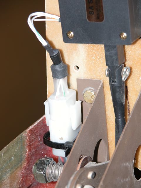
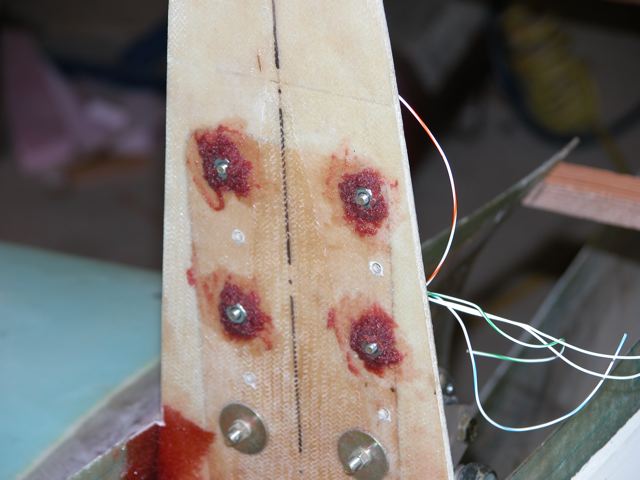
At that stage of the build, I was not comfortable w/ using D sub terminals and questioned my ability to disconnect them w/ one hand
I used this AMP connector w/ the larger, crimped pins
I also floxed the nuts on the back face of the bulkhead which hold the servo in position, though Id use nut plates were I to do it again
Fred
[img]cid:F3B43775-537A-4795-ADFC-E87FDBB1ED99[/img]
[img]cid:3D326174-983F-4991-8A87-890A5822350B[/img]
| | - The Matronics Europa-List Email Forum - | | | Use the List Feature Navigator to browse the many List utilities available such as the Email Subscriptions page, Archive Search & Download, 7-Day Browse, Chat, FAQ, Photoshare, and much more:
http://www.matronics.com/Navigator?Europa-List |
|
| Description: |
|
| Filesize: |
47.41 KB |
| Viewed: |
6313 Time(s) |
|
| Description: |
|
| Filesize: |
42.13 KB |
| Viewed: |
6313 Time(s) |
|
|
|
| Back to top |
|
|
davidjoyce(at)doctors.org
Guest
|
| Posted: Wed May 21, 2014 8:55 am Post subject: Electrical Wiring |
|
|
I have just tried to replace my servo before discovering
that the fault lay in one of the connectors in an awkward
position behind the panel (actually a snapped wire going
into a crimped pin). In speaking to the guy at Ray Allen,
he was v. Surprised to hear that the servo had packed up,
and implied that they just don't do that even after as
many hours service as mine - and he proved correct when I
released the wiring and retested it. My advice would be to
solder the wires at the servo end to the same coloured
wires in the multicore cable also supplied by Ray Allen,
supporting individual joins and the whole bundle with
heatshrink and also supporting the cable near to the
servo, etc. I feel this is less likely to cause problems
than a connector, and in the very unlikely event that you
do need to replace the servo, replacing soldered joints is
no great issue. Incidentally I have a brand new servo
still in its original sealed pack should anyone need one!
Regards, David Joyce, G- XSDJ
On Wed, 21 May 2014 07:09:54 -0700
Fred Klein <fklein(at)orcasonline.com> wrote:
| Quote: |
On May 21, 2014, at 2:32 AM, Tony Renshaw
<tonyrenshaw268(at)gmail.com> wrote:
> I am interested in what is the correct or preferred
>connector for the small wires in the RayAllen Servo wire
>bundles etc., the small dia cabling of many devices. Im
>sure there are some better than others, but I currently
>dont know any, albeit a ACS catalogue could narrow it
>down. So far, I have tried D sub terminals, as they are
>easy to get and easy to solder. Should I stick with
>them??
Tony
At that stage of the build, I was not comfortable
w/ using D sub terminals and questioned my ability to
disconnect them w/ one hand
I used this AMP connector w/
the larger, crimped pins
I also floxed the nuts on the
back face of the bulkhead which hold the servo in
position, though Id use nut plates were I to do it
again
Fred
|
| | - The Matronics Europa-List Email Forum - | | | Use the List Feature Navigator to browse the many List utilities available such as the Email Subscriptions page, Archive Search & Download, 7-Day Browse, Chat, FAQ, Photoshare, and much more:
http://www.matronics.com/Navigator?Europa-List |
|
|
|
| Back to top |
|
|
Fred Klein
Joined: 26 Mar 2012
Posts: 503
|
| Posted: Wed May 21, 2014 11:52 am Post subject: Electrical Wiring |
|
|
On May 21, 2014, at 7:40 AM, Bob Harrison <ptag.dev(at)talktalk.net (ptag.dev(at)talktalk.net)> wrote:
| Quote: | | it occurs to me having looked at your photo of your servo and the plastic clevises to ask if you have shortened them before connecting them with the piece of threaded rod? You are headed for some hassle if you havent, since you wont get enough trim through the operating range of the Stabilators without the bottom clevis fouling up on the operating lever at the end of the travel range.. ( I think that was the best description of the problem but check it out Fred before you close it up with the top on!) |
Bob,
Thank you for taking a close look at my build photo
as I read your post, youre asking if I have shortened the plastic clevises.
From the XS build manual, I read:
| Quote: | Cut off a 32 mm (11/4) piece of the threaded rod and screw on the two plastic fork-ends until they are butted together
|
I read nothing about shortening the plastic clevises; rather, it appears to me that the intent of the instructions is to ensure that the shortened length of threaded rod allows for the plastic fork-ends to abut one another.
My top has been bonded on for several years, so you raise a possible issue of some significance.
Have I missed a bit of Europa-lore which never made it into print in the manual?
or what?
All comments appreciated,
Fred
[quote][b]
| | - The Matronics Europa-List Email Forum - | | | Use the List Feature Navigator to browse the many List utilities available such as the Email Subscriptions page, Archive Search & Download, 7-Day Browse, Chat, FAQ, Photoshare, and much more:
http://www.matronics.com/Navigator?Europa-List |
|
|
|
| Back to top |
|
|
ptag.dev(at)talktalk.net
Guest
|
| Posted: Wed May 21, 2014 12:10 pm Post subject: Electrical Wiring |
|
|
Hi! Fred,
Better check with another “oracle” then but I remember first sizing the clevises and then making the threaded rod to fit. What you need to do is operate the trim motor to it’s full travel position both ways to ensure that the lever they are driving doesn’t foul up on the root of the clevis before the motor stops.
Sorry if I may have caused some confusion but I recall needing to size the clevises first and yours are clearly to be seen untouched? Of Course all these years on things may have changed. But it is interesting no one else has commented?
Regards
Bob H G-PTAG
From: owner-europa-list-server(at)matronics.com [mailto:owner-europa-list-server(at)matronics.com] On Behalf Of Fred Klein
Sent: 21 May 2014 20:51
To: europa-list(at)matronics.com
Subject: Re: Electrical Wiring
On May 21, 2014, at 7:40 AM, Bob Harrison <ptag.dev(at)talktalk.net (ptag.dev(at)talktalk.net)> wrote:
it occurs to me having looked at your photo of your servo and the plastic clevises to ask if you have shortened them before connecting them with the piece of threaded rod? You are headed for some hassle if you haven’t, since you won’t get enough trim through the operating range of the Stabilators without the bottom clevis fouling up on the operating lever at the end of the travel range.. ( I think that was the best description of the problem but check it out Fred before you close it up with the top on!)
Bob,
Thank you for taking a close look at my build photo…as I read your post, you’re asking if I have shortened the plastic clevises.
From the XS build manual, I read:
| Quote: |
Cut off a 32 mm (11/4“) piece of the threaded rod and screw on the two plastic fork-ends until they are butted together
|
I read nothing about shortening the plastic clevises; rather, it appears to me that the intent of the instructions is to ensure that the shortened length of threaded rod allows for the plastic fork-ends to abut one another.
My top has been bonded on for several years, so you raise a possible issue of some significance.
Have I missed a bit of Europa-lore which never made it into print in the manual?…or what?
All comments appreciated,
Fred
| Quote: | | http://www.matronics.com/Navigator?Europa-List |
01234567
[quote][b]
| | - The Matronics Europa-List Email Forum - | | | Use the List Feature Navigator to browse the many List utilities available such as the Email Subscriptions page, Archive Search & Download, 7-Day Browse, Chat, FAQ, Photoshare, and much more:
http://www.matronics.com/Navigator?Europa-List |
|
|
|
| Back to top |
|
|
Fred Klein
Joined: 26 Mar 2012
Posts: 503
|
| Posted: Wed May 21, 2014 12:29 pm Post subject: Electrical Wiring |
|
|
Bob
I do recall using a 9v. battery to check for full travel
Ill be interested to hear whether other listers found it necessary...as you apparently did
to trim the plastic fork-ends in order to avoid a foul up on the root of the clevis before the motor stops
Fred
On May 21, 2014, at 1:09 PM, Bob Harrison <ptag.dev(at)talktalk.net (ptag.dev(at)talktalk.net)> wrote:
| Quote: | Hi! Fred,
Better check with another oracle then but I remember first sizing the clevises and then making the threaded rod to fit. What you need to do is operate the trim motor to its full travel position both ways to ensure that the lever they are driving doesnt foul up on the root of the clevis before the motor stops.
Sorry if I may have caused some confusion but I recall needing to size the clevises first and yours are clearly to be seen untouched? Of Course all these years on things may have changed. But it is interesting no one else has commented?
Regards
Bob H G-PTAG
From: owner-europa-list-server(at)matronics.com (owner-europa-list-server(at)matronics.com) [mailto:owner-europa-list-server(at)matronics.com (owner-europa-list-server(at)matronics.com)] On Behalf Of Fred Klein
Sent: 21 May 2014 20:51
To: europa-list(at)matronics.com (europa-list(at)matronics.com)
Subject: Re: Electrical Wiring
On May 21, 2014, at 7:40 AM, Bob Harrison <ptag.dev(at)talktalk.net (ptag.dev(at)talktalk.net)> wrote:
it occurs to me having looked at your photo of your servo and the plastic clevises to ask if you have shortened them before connecting them with the piece of threaded rod? You are headed for some hassle if you havent, since you wont get enough trim through the operating range of the Stabilators without the bottom clevis fouling up on the operating lever at the end of the travel range.. ( I think that was the best description of the problem but check it out Fred before you close it up with the top on!)
Bob,
Thank you for taking a close look at my build photo
as I read your post, youre asking if I have shortened the plastic clevises.
From the XS build manual, I read:
| Quote: | Cut off a 32 mm (11/4) piece of the threaded rod and screw on the two plastic fork-ends until they are butted together
|
I read nothing about shortening the plastic clevises; rather, it appears to me that the intent of the instructions is to ensure that the shortened length of threaded rod allows for the plastic fork-ends to abut one another.
My top has been bonded on for several years, so you raise a possible issue of some significance.
Have I missed a bit of Europa-lore which never made it into print in the manual?
or what?
All comments appreciated,
Fred
01234567
8
|
[quote][b]
| | - The Matronics Europa-List Email Forum - | | | Use the List Feature Navigator to browse the many List utilities available such as the Email Subscriptions page, Archive Search & Download, 7-Day Browse, Chat, FAQ, Photoshare, and much more:
http://www.matronics.com/Navigator?Europa-List |
|
|
|
| Back to top |
|
|
fireflier
Joined: 24 Jun 2012
Posts: 58
|
| Posted: Wed May 21, 2014 12:41 pm Post subject: Electrical Wiring |
|
|
Hi Fred
I think Bob might be correct. From memory when i installed mine i had to shorten the fork ends.
The reason being when connected to the bellcrank and you operate the servo it can bind in one direction.
You will know if its binding as it labours near the end of the travel.
This check is part of the final checklist, to ensure the trim servo moves through its complete range with no binding at all.
Hope this helps
Kind regards
Donald
G-PUPY (nearly flying awaiting paperwork from LAA to test fly)
Sent from my iPhone
On 21 May 2014, at 21:28, Fred Klein <fklein(at)orcasonline.com (fklein(at)orcasonline.com)> wrote:
[quote]Bobâ¦I do recall using a 9v. battery to check for full travelâ¦Iâll be interested to hear whether other listers found it necessary...as you apparently didâ¦to trim the plastic fork-ends in order to avoid a âfoul up on the root of the clevis before the motor stopsââ¦Fred
On May 21, 2014, at 1:09 PM, Bob Harrison <ptag.dev(at)talktalk.net (ptag.dev(at)talktalk.net)> wrote:
| Quote: | Hi! Fred,
Better check with another âoracleâ then but I remember first sizing the clevises and then making the threaded rod to fit. What you need to do is operate the trim motor to itâs full travel position both ways to ensure that the lever they are driving doesnât foul up on the root of the clevis before the motor stops.
Sorry if I may have caused some confusion but I recall needing to size the clevises first and yours are clearly to be seen untouched? Of Course all these years on things may have changed. But it is interesting no one else has commented?
Regards
Bob H G-PTAG
From: owner-europa-list-server(at)matronics.com (owner-europa-list-server(at)matronics.com) [mailto:owner-europa-list-server(at)matronics.com (owner-europa-list-server(at)matronics.com)] On Behalf Of Fred Klein
Sent: 21 May 2014 20:51
To: europa-list(at)matronics.com (europa-list(at)matronics.com)
Subject: Re: Electrical Wiring
On May 21, 2014, at 7:40 AM, Bob Harrison <ptag.dev(at)talktalk.net (ptag.dev(at)talktalk.net)> wrote:
it occurs to me having looked at your photo of your servo and the plastic clevises to ask if you have shortened them before connecting them with the piece of threaded rod? You are headed for some hassle if you havenât, since you wonât get enough trim through the operating range of the Stabilators without the bottom clevis fouling up on the operating lever at the end of the travel range.. ( I think that was the best description of the problem but check it out Fred before you close it up with the top on!)
Bob,
Thank you for taking a close look at my build photoâ¦as I read your post, youâre asking if I have shortened the plastic clevises.
From the XS build manual, I read:
| Quote: | Cut off a 32 mm (11/4â) piece of the threaded rod and screw on the two plastic fork-ends until they are butted together
|
I read nothing about shortening the plastic clevises; rather, it appears to me that the intent of the instructions is to ensure that the shortened length of threaded rod allows for the plastic fork-ends to abut one another.
My top has been bonded on for several years, so you raise a possible issue of some significance.
Have I missed a bit of Europa-lore which never made it into print in the manual?â¦or what?
All comments appreciated,
Fred
01234567
8
|
9
[b]
| | - The Matronics Europa-List Email Forum - | | | Use the List Feature Navigator to browse the many List utilities available such as the Email Subscriptions page, Archive Search & Download, 7-Day Browse, Chat, FAQ, Photoshare, and much more:
http://www.matronics.com/Navigator?Europa-List |
|
_________________
Fireflier |
|
| Back to top |
|
|
Fred Klein
Joined: 26 Mar 2012
Posts: 503
|
| Posted: Wed May 21, 2014 2:07 pm Post subject: Electrical Wiring |
|
|
On May 21, 2014, at 1:41 PM, Donald Cameron <fireflier(at)btinternet.com (fireflier(at)btinternet.com)> wrote:
| Quote: | From memory when i installed mine i had to shorten the fork ends.
|
Don
not exactly what I wanted to hear, but I thank you nonetheless for responding to my request
after poking around a bit, I dont see any insurmountable problems to trimming my plastic clevises at this late stage of the game.
Though Im wondering
when you shorten(ed) the fork ends, were you trimming literally the ends of forks thru which the clevis pin fits?
or did you shorten what Ill call the base of the clevis, i.e., the opposite end where the two clevises abut one another after being brought together by the threaded rod?
Good luck with your paperwork
Im rather envious,
Fred
[quote][b]
| | - The Matronics Europa-List Email Forum - | | | Use the List Feature Navigator to browse the many List utilities available such as the Email Subscriptions page, Archive Search & Download, 7-Day Browse, Chat, FAQ, Photoshare, and much more:
http://www.matronics.com/Navigator?Europa-List |
|
|
|
| Back to top |
|
|
rlborger(at)mac.com
Guest
|
| Posted: Wed May 21, 2014 4:03 pm Post subject: Electrical Wiring |
|
|
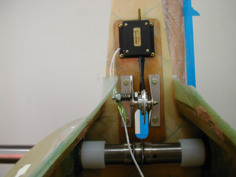
Hay Fred,
Dont fret. I did mine just like yours:
[img]cid:1D08E18E-513A-4570-A8E3-43E8A951043D[/img]
It works just fine. Thats the way my instructions said to do it:
Trim servo
Step 5
Unpack the MAC electric trim servo and study all the instructions.
Cut off a 32 mm (11/4) piece of the threaded rod and screw on the two plastic fork-ends until they are
butted together.
There must have been a change in the instructions somewhere along the way.
Blue skies & tailwinds,Bob BorgerEuropa XS Tri, Rotax 914, Airmaster C/S Prop (50 hrs).Little Toot Sport Biplane, Lycoming Thunderbolt AEIO-320 EXP3705 Lynchburg Dr.Corinth, TX 76208-5331Cel: 817-992-1117rlborger(at)mac.com (rlborger(at)mac.com)
On May 21, 2014, at 5:06 PM, Fred Klein <fklein(at)orcasonline.com (fklein(at)orcasonline.com)> wrote:
On May 21, 2014, at 1:41 PM, Donald Cameron <fireflier(at)btinternet.com (fireflier(at)btinternet.com)> wrote:
| Quote: | From memory when i installed mine i had to shorten the fork ends.
|
Don
not exactly what I wanted to hear, but I thank you nonetheless for responding to my request
after poking around a bit, I dont see any insurmountable problems to trimming my plastic clevises at this late stage of the game.
Though Im wondering
when you shorten(ed) the fork ends, were you trimming literally the ends of forks thru which the clevis pin fits?
or did you shorten what Ill call the base of the clevis, i.e., the opposite end where the two clevises abut one another after being brought together by the threaded rod?
Good luck with your paperwork
Im rather envious,
Fred
| Quote: |
href="http://www.matronics.com/Navigator?Europa-List">http://www.matronics.com/Navigator?Europa-List
href="http://forums.matronics.com/">http://forums.matronics.com
href="http://www.matronics.com/contribution">http://www.matronics.com/contribution
|
| | - The Matronics Europa-List Email Forum - | | | Use the List Feature Navigator to browse the many List utilities available such as the Email Subscriptions page, Archive Search & Download, 7-Day Browse, Chat, FAQ, Photoshare, and much more:
http://www.matronics.com/Navigator?Europa-List |
|
| Description: |
|
| Filesize: |
291.78 KB |
| Viewed: |
6293 Time(s) |
|
|
|
| Back to top |
|
|
spcialeffects
Joined: 29 Aug 2012
Posts: 306
Location: Kent
|
| Posted: Thu May 22, 2014 9:42 am Post subject: Re: Electrical Wiring |
|
|
I have just fitted my trim motor two days ago so this was good timing! so i did per the instructions and cut off the required tread and butted the plastic forks together. I then found that when the motor was fully extended out it would catch or rather bottom out on the cut out of the bell crank support. i extended the cut out after speaking with another builder and this allowed full travel of the trim motor.
| | - The Matronics Europa-List Email Forum - | | | Use the List Feature Navigator to browse the many List utilities available such as the Email Subscriptions page, Archive Search & Download, 7-Day Browse, Chat, FAQ, Photoshare, and much more:
http://www.matronics.com/Navigator?Europa-List |
|
|
|
| Back to top |
|
|
budyerly(at)msn.com
Guest
|
| Posted: Thu May 22, 2014 2:20 pm Post subject: Electrical Wiring |
|
|
<?xml:namespace prefix="v" /><?xml:namespace prefix="o" /><![endif]-->  Tony,

 Your build experience will be enhanced by learning how to do DSub  connectors properly.  Pins and Sockets may be purchased at very cheap  prices (even in gold plated connectors as I use).


 I use Allied Electric (alliedelec.com) as my primary supplier.  All  your avionics uses D subs.  Garmin supplies and prefers the mil spec pins  and sockets, but many others are available.  I use Tyco (TE  Technology) or Amp primarily.

 Tools you need are:

 A crimper  (I use an Eclipse pro grade one, and my friend uses a Quest  technology ratcheting type for open crimp type pins which crimp the wire and  insulation for a great connection as well as my megabuck  one.)        (I use a Quest Tech for my  barrel pin connector crimper.)   Even Radio Shack has pretty good  tools.


 A D sub pin and socket extractor tool will be necessary.


 A good wire stripper.


 And you will find 9 and 25 pin are the the most common used in the  aircraft.

 Connectors are only a few bucks, hardware a couple more and pins come in  sizes from AWG 30 wire to #18 and run about $.030.


 I also like circular connectors for my through the firewall and  airframe to panel hookups.


 More tools and fun gadgets.


 After all, you built it, you can maintain it far cheaper than hiring  someone.  But you need to do the study and practice.


 If I run a wire anywhere, it terminates in a plug with a bit of a  maintenance loop or S turn to facilitate maintenance.  If it is electric,  assume it will fail.  Especially make sure you have connectors that are  easy to latch where it is difficult to get to or work.  Manufacturers make  all different kind of connectors and hardware.


 I do deviate from the book when it comes to inspection holes.  I  believe an inspection hole must be big enough to work in, not just look and  scratch your head to try to figure out how to fix something using tweasers and  forceps while looking backwards through a mirror.


 Enjoy Building

 Bud Yerly


 [quote]   ---
| | - The Matronics Europa-List Email Forum - | | | Use the List Feature Navigator to browse the many List utilities available such as the Email Subscriptions page, Archive Search & Download, 7-Day Browse, Chat, FAQ, Photoshare, and much more:
http://www.matronics.com/Navigator?Europa-List |
|
|
|
| Back to top |
|
|
|
|
You cannot post new topics in this forum
You cannot reply to topics in this forum
You cannot edit your posts in this forum
You cannot delete your posts in this forum
You cannot vote in polls in this forum
You cannot attach files in this forum
You can download files in this forum
|
Powered by phpBB © 2001, 2005 phpBB Group
|

