 |
Matronics Email Lists
Web Forum Interface to the Matronics Email Lists
|
| View previous topic :: View next topic |
| Author |
Message |
jmjones2000(at)mindspring
Guest
|
 Posted: Sun Oct 26, 2014 9:34 pm Post subject: B&C alternator question Posted: Sun Oct 26, 2014 9:34 pm Post subject: B&C alternator question |
 |
|
In the Z-13/8 Diagram, it specifies the use of an SD-8 PM as the standby alternator. Is it acceptable to replace it with a BC410-H 20A and use a generic ford voltage regulator? Or is it necessary to use a B&C alternator controller? I would connect it to the system in the same place (battery side of the battery contractor). In the event of a primary alternator failure, I require 12A (worst case scenario) to continue to run necessary systems without discharging the battery. The SD-8 doesnt seem up to the task, not to mention the BC410-H is a less expensive option.
Thanks!
Justin
| | - The Matronics AeroElectric-List Email Forum - | | | Use the List Feature Navigator to browse the many List utilities available such as the Email Subscriptions page, Archive Search & Download, 7-Day Browse, Chat, FAQ, Photoshare, and much more:
http://www.matronics.com/Navigator?AeroElectric-List |
|
|
|
| Back to top |
|
 |
millner(at)me.com
Guest
|
| Posted: Sun Oct 26, 2014 11:15 pm Post subject: B&C alternator question |
|
|
| Quote: | > Is it acceptable to replace it with a BC410-H 20A and use a generic ford voltage regulator? Or is it necessary to use a B&C alternator controller?
|
Justin,
If you try to use an automotive Ford regulator, my experience shows you'll find that an attempt to shutdown that alternator in the conventional method, by switching off the field power to the regulator, will instead result in a voltage runaway, with the regulator powering itself from the alternator directly with NO regulation of voltage. Once that happens, turning the field power back on does NOT result in voltage control... Overvoltage continues. The only way to restore normal regulation is powering down the alternator, which usually means engine shutdown... Not handy.
Paul
| | - The Matronics AeroElectric-List Email Forum - | | | Use the List Feature Navigator to browse the many List utilities available such as the Email Subscriptions page, Archive Search & Download, 7-Day Browse, Chat, FAQ, Photoshare, and much more:
http://www.matronics.com/Navigator?AeroElectric-List |
|
|
|
| Back to top |
|
|
fvalarm(at)rapidnet.net
Guest
|
| Posted: Sun Oct 26, 2014 11:42 pm Post subject: B&C alternator question |
|
|
Justin,


Are you sure that your CONTINUOUS Ebus load is greater than 10amps?

Momentary loads over 10 amps will source the excess from the battery, and

then recharge as the peak load drops off.   If you can, measure your actual

loads.  Measured loads will likely be less than what's published by the

manufacturer as those are likely maximums.  Kind of like rounding up.  If

you add a bunch of rounded up numbers together, you get a much higher number

than actual.


Bevan


--
| | - The Matronics AeroElectric-List Email Forum - | | | Use the List Feature Navigator to browse the many List utilities available such as the Email Subscriptions page, Archive Search & Download, 7-Day Browse, Chat, FAQ, Photoshare, and much more:
http://www.matronics.com/Navigator?AeroElectric-List |
|
|
|
| Back to top |
|
|
jmjones2000(at)mindspring
Guest
|
| Posted: Mon Oct 27, 2014 12:20 am Post subject: B&C alternator question |
|
|
I am sure the continuous required load will be greater than 10A.  I live in Alaska and I am including the Pitot heat into the equation.  The aircraft that I am building is all electric (instruments and engine).  I will be flying quite a bit at night and MVFR with the potential of IFR flights.  Conditions conducive to Pitot Tube icing exist often up here.  With the ECUs, Ignition Coils, Fuel Pumps, EFIS, GPS, Engine Monitor, Pitot Heat and required lights, I am over 10A.  My goal is to have an electrical contingent based on my worst case scenario.  This would be a marginal weather flight, at night over remote stretches of wilderness or water.  I will not be doing these types of flights often, but the majority of flying that I will do with this airplane will be off-airport operations.  I would like to have the option to use the devices that I may need without the concern of discharging the battery.  I would be more comfortable on these more dangerous, higher risk flights if I knew that my back-up alternator system was capable of handling a primary alternator failure without having to decide what items to shut off in order to shed a load.  I am designing the limiting factor in the system to be fuel remaining.  It is also a perk that the larger alternator is less expensive.


Justin

On Oct 26, 2014, at 11:42 PM, B Tomm <fvalarm(at)rapidnet.net> wrote:


[quote]


 Justin,


 Are you sure that your CONTINUOUS Ebus load is greater than 10amps?

 Momentary loads over 10 amps will source the excess from the battery, and

 then recharge as the peak load drops off.   If you can, measure your actual

 loads.  Measured loads will likely be less than what's published by the

 manufacturer as those are likely maximums.  Kind of like rounding up.  If

 you add a bunch of rounded up numbers together, you get a much higher number

 than actual.


 Bevan


 --
| | - The Matronics AeroElectric-List Email Forum - | | | Use the List Feature Navigator to browse the many List utilities available such as the Email Subscriptions page, Archive Search & Download, 7-Day Browse, Chat, FAQ, Photoshare, and much more:
http://www.matronics.com/Navigator?AeroElectric-List |
|
|
|
| Back to top |
|
|
nuckolls.bob(at)aeroelect
Guest
|
| Posted: Mon Oct 27, 2014 6:31 am Post subject: B&C alternator question |
|
|
At 00:32 2014-10-27, you wrote:
| Quote: | --> AeroElectric-List message posted by: Justin Jones <jmjones2000(at)mindspring.com>
In the Z-13/8 Diagram, it specifies the use of an SD-8 PM as the standby alternator. Is it acceptable to replace it with a BC410-H 20A and use a generic ford voltage regulator? Or is it necessary to use a B&C alternator controller? I would connect it to the system in the same place (battery side of the battery contractor). In the event of a primary alternator failure, I require 12A (worst case scenario) to continue to run necessary systems without discharging the battery. The SD-8 doesnt seem up to the task, not to mention the BC410-H is a less expensive option. |
Suggest go with Z-12 and use ANY of the larger,
B&C pad-driven alternators.
The generic Ford regulators are 'okay' . . .
they perform as advertised but they are
not adjustable. Z-12 was orignially crafed
to accommodate an 'auto switching' mode
for the stand-by alternator (like those
systems installed on many, many TC aircraft.
The standby system is ON all the time with
a voltage regulator set for 1.0 volts below
the normal system voltage set-point. If the
main alternator goes south, bus voltage drops,
the s/b regulator tells the little alternator
to go to work. If you're using the B&C SB-1
controller, it will light an annunciator to
tell you that the alternator is on-line.
If in an overloaded state, the light will
flash. You then reduce loads until the light
is on steady indicating that the loads are
now within the alternator's capabilities.
If you don't want/need the auto-switched feature,
use the generic Ford regulator if you wish.
Leave s/b alternator OFF until advised that
it is needed by a low-volts warning whereupon
you bring the s/b alternator on line and
then adjust loads to keep the bus voltage
at the regulator's set-point or some value
at or below 100% of alternator's output as
displayed on a loadmeter.
KISS . . . Z-12 is recommended. I used to
have a Figure Z-13/20 that proved to be
rather in-elegant and I removed it.
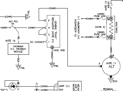
Wire your "Ford" regulator thusly . . .
[img]cid:.0[/img]
. . . as depicted in Figure Z-11.
Bob . . .
| | - The Matronics AeroElectric-List Email Forum - | | | Use the List Feature Navigator to browse the many List utilities available such as the Email Subscriptions page, Archive Search & Download, 7-Day Browse, Chat, FAQ, Photoshare, and much more:
http://www.matronics.com/Navigator?AeroElectric-List |
|
| Description: |
|
| Filesize: |
48.8 KB |
| Viewed: |
5178 Time(s) |
|
|
|
| Back to top |
|
|
nuckolls.bob(at)aeroelect
Guest
|
| Posted: Mon Oct 27, 2014 6:39 am Post subject: B&C alternator question |
|
|
At 01:59 2014-10-27, you wrote:
| Quote: |
>> Is it acceptable to replace it with a BC410-H 20A and use a
generic ford voltage regulator? Or is it necessary to use a B&C
alternator controller?
Justin,
If you try to use an automotive Ford regulator, my experience shows
you'll find that an attempt to shutdown that alternator in the
conventional method, by switching off the field power to the
regulator, will instead result in a voltage runaway, with the
regulator powering itself from the alternator directly with NO
regulation of voltage. Once that happens, turning the field power
back on does NOT result in voltage control... Overvoltage continues.
The only way to restore normal regulation is powering down the
alternator, which usually means engine shutdown... Not handy.
|
This is a condition limited to the Cessna's which
do not tie "A" and "S" terminals together . . . a
condition that's okay for the legacy electro-mechanical
regulators and their solid-state clones.
The commercial off-the shelf replacement regulators
are sometimes wired a little differently within . . .
which does not affect their performance in cars
where alternators are not controlled. These not-
quite-a-clone variants will indeed produce the
behavior your describe . . . been there, done that.
But when wired as depicted in Z-11 and others, the
generic COTS regulators of all stripe are well
behaved performers.
Bob . . .
| | - The Matronics AeroElectric-List Email Forum - | | | Use the List Feature Navigator to browse the many List utilities available such as the Email Subscriptions page, Archive Search & Download, 7-Day Browse, Chat, FAQ, Photoshare, and much more:
http://www.matronics.com/Navigator?AeroElectric-List |
|
|
|
| Back to top |
|
|
nuckolls.bob(at)aeroelect
Guest
|
| Posted: Mon Oct 27, 2014 6:39 am Post subject: B&C alternator question |
|
|
At 03:19 2014-10-27, you wrote:


<jmjones2000(at)mindspring.com>


I am sure the continuous required load will be greater than 10A.  I

live in Alaska and I am including the Pitot heat into the

equation.  The aircraft that I am building is all electric

(instruments and engine).  I will be flying quite a bit at night and

MVFR with the potential of IFR flights.  Conditions conducive to

Pitot Tube icing exist often up here.  With the ECUs, Ignition Coils,

Fuel Pumps, EFIS, GPS, Engine Monitor, Pitot Heat and required

lights, I am over 10A.  My goal is to have an electrical contingent

based on my worst case scenario.  This would be a marginal weather

flight, at night over remote stretches of wilderness or water.  I

will not be doing these types of flights often, but the majority of

flying that I will do with this airplane will be off-airport

operations.  I would like to have the option to use the devices that

I may need without the concern of discharging the battery.  I would

be more comfortable on these more dangerous, higher risk flights if I

knew that my back-up alternator system was capable of handling a

primary alternator failure without having to decide what items to

shut off in order to shed a load.  I am designing the limiting factor

in the system to be fuel remaining.  It is also a perk that the

larger alternator is less expensive.


Justin


    Have you done a load analysis? These are non-

    quantified assertions that are easily converted

    to conditions of KNOWN significance with a little

    pencil pushing . . .


    Define "worst case" scenario and put a number on it . . .

   Bob . . .
| | - The Matronics AeroElectric-List Email Forum - | | | Use the List Feature Navigator to browse the many List utilities available such as the Email Subscriptions page, Archive Search & Download, 7-Day Browse, Chat, FAQ, Photoshare, and much more:
http://www.matronics.com/Navigator?AeroElectric-List |
|
|
|
| Back to top |
|
|
handainc(at)madisoncounty
Guest
|
| Posted: Mon Oct 27, 2014 7:09 am Post subject: B&C alternator question |
|
|
What is your opinion on the Zeftonici regulators? I had nothing but trouble with regulators when I got my Pacer, and then heard about Zeftronics. They got an STC for the Pacer PA20, and I put one on. It has been absolutely trouble free for 20+ years, and I don't remember it being very expensive.
M. Haught
On Oct 27, 2014, at 9:29 AM, Robert L. Nuckolls, III wrote:
[quote] At 00:32 2014-10-27, you wrote:
| Quote: | --> AeroElectric-List message posted by: Justin Jones <jmjones2000(at)mindspring.com (jmjones2000(at)mindspring.com)>
In the Z-13/8 Diagram, it specifies the use of an SD-8 PM as the standby alternator. Is it acceptable to replace it with a BC410-H 20A and use a generic ford voltage regulator? Or is it necessary to use a B&C alternator controller? I would connect it to the system in the same place (battery side of the battery contractor). In the event of a primary alternator failure, I require 12A (worst case scenario) to continue to run necessary systems without discharging the battery. The SD-8 doesnt seem up to the task, not to mention the BC410-H is a less expensive option. |
Suggest go with Z-12 and use ANY of the larger,
B&C pad-driven alternators.
The generic Ford regulators are 'okay' . . .
they perform as advertised but they are
not adjustable. Z-12 was orignially crafed
to accommodate an 'auto switching' mode
for the stand-by alternator (like those
systems installed on many, many TC aircraft.
The standby system is ON all the time with
a voltage regulator set for 1.0 volts below
the normal system voltage set-point. If the
main alternator goes south, bus voltage drops,
the s/b regulator tells the little alternator
to go to work. If you're using the B&C SB-1
controller, it will light an annunciator to
tell you that the alternator is on-line.
If in an overloaded state, the light will
flash. You then reduce loads until the light
is on steady indicating that the loads are
now within the alternator's capabilities.
If you don't want/need the auto-switched feature,
use the generic Ford regulator if you wish.
Leave s/b alternator OFF until advised that
it is needed by a low-volts warning whereupon
you bring the s/b alternator on line and
then adjust loads to keep the bus voltage
at the regulator's set-point or some value
at or below 100% of alternator's output as
displayed on a loadmeter.
KISS . . . Z-12 is recommended. I used to
have a Figure Z-13/20 that proved to be
rather in-elegant and I removed it.
Wire your "Ford" regulator thusly . . .
<21fe9360.jpg>
. . . as depicted in Figure Z-11.
Bob . . .
[b]
| | - The Matronics AeroElectric-List Email Forum - | | | Use the List Feature Navigator to browse the many List utilities available such as the Email Subscriptions page, Archive Search & Download, 7-Day Browse, Chat, FAQ, Photoshare, and much more:
http://www.matronics.com/Navigator?AeroElectric-List |
|
|
|
| Back to top |
|
|
Kellym
Joined: 10 Jan 2006
Posts: 1705
Location: Sun Lakes AZ
|
| Posted: Mon Oct 27, 2014 7:19 am Post subject: B&C alternator question |
|
|
Is there any concern with the vacuum pump pad driven alternators of the
coupling to the engine gears failing?
I assume they have some sort of shear or slip connection to protect the
engine from a bearing seizure.
Does the electrical load imposed have any effect on that coupling?
On 10/27/2014 7:29 AM, Robert L. Nuckolls, III wrote:
| Quote: | At 00:32 2014-10-27, you wrote:
>
> <jmjones2000(at)mindspring.com>
>
> In the Z-13/8 Diagram, it specifies the use of an SD-8 PM as the
> standby alternator. Is it acceptable to replace it with a BC410-H
> 20A and use a generic ford voltage regulator? Or is it necessary to
> use a B&C alternator controller? I would connect it to the system in
> the same place (battery side of the battery contractor). In the
> event of a primary alternator failure, I require 12A (worst case
> scenario) to continue to run necessary systems without discharging
> the battery. The SD-8 doesnt seem up to the task, not to mention the
> BC410-H is a less expensive option.
Suggest go with Z-12 and use ANY of the larger,
B&C pad-driven alternators.
The generic Ford regulators are 'okay' . . .
they perform as advertised but they are
not adjustable. Z-12 was orignially crafed
to accommodate an 'auto switching' mode
for the stand-by alternator (like those
systems installed on many, many TC aircraft.
The standby system is ON all the time with
a voltage regulator set for 1.0 volts below
the normal system voltage set-point. If the
main alternator goes south, bus voltage drops,
the s/b regulator tells the little alternator
to go to work. If you're using the B&C SB-1
controller, it will light an annunciator to
tell you that the alternator is on-line.
If in an overloaded state, the light will
flash. You then reduce loads until the light
is on steady indicating that the loads are
now within the alternator's capabilities.
If you don't want/need the auto-switched feature,
use the generic Ford regulator if you wish.
Leave s/b alternator OFF until advised that
it is needed by a low-volts warning whereupon
you bring the s/b alternator on line and
then adjust loads to keep the bus voltage
at the regulator's set-point or some value
at or below 100% of alternator's output as
displayed on a loadmeter.
KISS . . . Z-12 is recommended. I used to
have a Figure Z-13/20 that proved to be
rather in-elegant and I removed it.
Wire your "Ford" regulator thusly . . .
Emacs!
. . . as depicted in Figure Z-11.
Bob . . .
|
| | - The Matronics AeroElectric-List Email Forum - | | | Use the List Feature Navigator to browse the many List utilities available such as the Email Subscriptions page, Archive Search & Download, 7-Day Browse, Chat, FAQ, Photoshare, and much more:
http://www.matronics.com/Navigator?AeroElectric-List |
|
_________________
Kelly McMullen
A&P/IA, EAA Tech Counselor # 5286
KCHD |
|
| Back to top |
|
|
jmjones2000(at)mindspring
Guest
|
| Posted: Mon Oct 27, 2014 8:55 pm Post subject: B&C alternator question |
|
|
Is there a way to wire 2 shunts to a single Ammeter using a selector switch? Looking at Z13-8, was this diagram designed to go to 2 separate ammeters? I have an engine monitor and was going to rely on that for my ammeter. Would it be acceptable to place a single shunt at the battery? This would tell me the amount of electrons coming and or going to/from the battery, but I am not sure this information will help me in a 2 alternator situation. Thank you in advance for your thoughts.
Justin
On Oct 27, 2014, at 6:34 AM, Robert L. Nuckolls, III <nuckolls.bob(at)aeroelectric.com> wrote:
| Quote: |
At 01:59 2014-10-27, you wrote:
>
>
> >> Is it acceptable to replace it with a BC410-H 20A and use a generic ford voltage regulator? Or is it necessary to use a B&C alternator controller?
>
> Justin,
>
> If you try to use an automotive Ford regulator, my experience shows you'll find that an attempt to shutdown that alternator in the conventional method, by switching off the field power to the regulator, will instead result in a voltage runaway, with the regulator powering itself from the alternator directly with NO regulation of voltage. Once that happens, turning the field power back on does NOT result in voltage control... Overvoltage continues. The only way to restore normal regulation is powering down the alternator, which usually means engine shutdown... Not handy.
This is a condition limited to the Cessna's which
do not tie "A" and "S" terminals together . . . a
condition that's okay for the legacy electro-mechanical
regulators and their solid-state clones.
The commercial off-the shelf replacement regulators
are sometimes wired a little differently within . . .
which does not affect their performance in cars
where alternators are not controlled. These not-
quite-a-clone variants will indeed produce the
behavior your describe . . . been there, done that.
But when wired as depicted in Z-11 and others, the
generic COTS regulators of all stripe are well
behaved performers.
Bob . . .
|
| | - The Matronics AeroElectric-List Email Forum - | | | Use the List Feature Navigator to browse the many List utilities available such as the Email Subscriptions page, Archive Search & Download, 7-Day Browse, Chat, FAQ, Photoshare, and much more:
http://www.matronics.com/Navigator?AeroElectric-List |
|
|
|
| Back to top |
|
|
jluckey(at)pacbell.net
Guest
|
| Posted: Mon Oct 27, 2014 10:53 pm Post subject: B&C alternator question |
|
|
Is there a way to wire 2 shunts to a single Ammeter using a selector switch?


Yes - you could use a double-pole, double-throw, on-on toggle switch (DPDT, on-on)

to switch between 2 shunts.  Keep in mind that both wires coming from

the shunt are hot B+ and need to be protected accordingly.


It is certainly acceptable to put the shunt at the battery, however in that position

one would normally use a zero-center ammeter and you  would have to confirm

that your engine monitor could display that info properly.


If you put the shunt at the  battery you would only need one to get satisfactory

current monitoring. (I'm assuming you're talking about a single battery system)


-Jeff


     On Monday, October 27, 2014 9:53 PM, Justin Jones <jmjones2000(at)mindspring.com> wrote:

   --> AeroElectric-List message posted by: Justin Jones <jmjones2000(at)mindspring.com (jmjones2000(at)mindspring.com)>Is there a way to wire 2 shunts to a single Ammeter using a selector switch?  Looking at Z13-8, was this diagram designed to go to 2 separate ammeters?  I have an engine monitor and was going to rely on that for my ammeter.  Would it be acceptable to place a single shunt at the battery? This would tell me the amount of electrons coming and or going to/from the battery, but I am not sure this information will help me in a 2 alternator situation.  Thank you in advance for your thoughts.JustinOn Oct 27, 2014, at 6:34 AM, Robert L. Nuckolls, III <nuckolls.bob(at)aeroelectric.com (nuckolls.bob(at)aeroelectric.com)> wrote:> --> AeroElectric-List message posted by: "Robert L. Nuckolls, III" <nuckolls.bob(at)aeroelectric.com (nuckolls.bob(at)aeroelectric.com)>> > At 01:59  2014-10-27, you wrote:>> --> AeroElectric-List message posted by: Paul Millner <millner(at)me.com (millner(at)me.com)>>> >> >>  Is it acceptable to replace it with a BC410-H 20A and use a generic ford voltage regulator?  Or is it necessary to use a B&C alternator controller?>> >> Justin,>> >> If you try to use an automotive Ford regulator, my experience shows you'll find that an attempt to shutdown that alternator in the conventional  method, by switching off the field power to the regulator, will instead result in a voltage runaway, with the regulator powering itself from the alternator directly with NO regulation of voltage. Once that happens, turning the field power back on does NOT result in voltage control... Overvoltage continues. The only way to restore normal regulation is powering down the alternator, which usually means engine shutdown... Not handy.> >  This is a condition limited to the Cessna's which>  do not tie "A" and "S" terminals together . . . a>  condition that's okay for the legacy electro-mechanical>  regulators and their solid-state clones.>  >  The commercial off-the shelf replacement regulators>  are sometimes wired a little differently within . . .>  which does not affect their performance in cars>  where alternators are not controlled. These not->  quite-a-clone variants will indeed produce the>  behavior your describe . . . been there, done that.> >  But when wired as depicted in Z-11 and others, the>  generic COTS regulators of all stripe are well
| | - The Matronics AeroElectric-List Email Forum - | | | Use the List Feature Navigator to browse the many List utilities available such as the Email Subscriptions page, Archive Search & Download, 7-Day Browse, Chat, FAQ, Photoshare, and much more:
http://www.matronics.com/Navigator?AeroElectric-List |
|
|
|
| Back to top |
|
|
nuckolls.bob(at)aeroelect
Guest
|
| Posted: Tue Oct 28, 2014 4:15 am Post subject: B&C alternator question |
|
|
At 23:53 2014-10-27, you wrote:

 --> AeroElectric-List message posted by: Justin Jones <jmjones2000(at)mindspring.com>


 Is there a way to wire 2 shunts to a single Ammeter using a selector switch?  Looking at Z13-8, was this diagram designed to go to 2 separate ammeters?  I have an engine monitor and was going to rely on that for my ammeter.  Would it be acceptable to place a single shunt at the battery? This would tell me the amount of electrons coming and or going to/from the battery, but I am not sure this information will help me in a 2 alternator situation.  Thank you in advance for your thoughts.


    I show a shunt for each alternator but just how

    those are treated downstream in your instrumentation

    is optional.  I used to offer a miniature loadmeter

    kit in both a single and two alternator configuration.

    See wiring on page 3 of this document.


  http://tinyurl.com/luxve9h


    Loadmeters are generally not something that offers

    in flight, cockpit management information. Unlike

    the outlets in your house that can be tasekd with

    powering a wide variety of loads over time, the loads

    on your ship's power sources (alternators) is,

    or should be, absolutely known. If you've conducted

    a load analysis and determined that (1) the main

    alternator will carry worst case, full-up loads and

    (2) Plan-B for using the aux alternator does not

    overtax that machine either, then presenting loads

    information on any kind of panel display is irrelevant

    to competent and low-risk operation of the airplane.


    Ammeters in cars and airplanes and later loadmeters

    in airplanes were nothing more than the pre-cursors

    to the LOW VOLTS warning light in contemporary designs.


    From Part 23 FARs we read ...


  (d) Instruments. A means must exist to indicate to appropriate flight crewmembers the electric power system quantities essential for safe operation.


   (1) For normal, utility, and acrobatic category airplanes with direct current systems, an ammeter that can be switched into each generator feeder may be used and, if only one generator exists, the ammeter may be in the battery feeder.


  (2) For commuter category airplanes, the essential electric power system quantities include the voltage and current supplied by each generator.

    My 1941 Pontiac had a -0+ reading battery ammeter, so did

    the 1950 Ercoupe I learned to fly in. In both cases, the

    instrument was intended to be a gross presentation of

    normal/abnormal ops. As long as the needle was near zero

    most of the time and never below zero except at low rpm

    and/or generator OFF, all was right with the universe

    of electrons.


    Today, we can easily craft and install precision

    voltage monitoring circuitry triggered at 13.0 volts

    to light an annunciator. Any bus supported above

    13.0 volts MUST be enjoying the benefit of a functioning

    alternator.


    The loadmeter MIGHT be useful as an cockpit operations

    management tool if your main alternator failure response

    (Plan B) calls for "reduce loads to 20A or less" . . .

    but you can and should deduce where all those switches

    should be ON THE GROUND and recorded in your flight ops

    document as part of your Plan-B.


    Figures Z-12 installed on a Bonanza includes the alternator

    B-lead current sensor system that drives the ALTERNATOR

    LOADED light. To minimize the changes to an already

    certified airplane with unknown constellation of accessories,

    it was necessary to say, "Reduce loads until the light

    stops flashing". But YOUR airplane has known loads therefore

    Plan-B switch positioning is a pre-ordained condition.

    Hence, no in-flight interpretation of alternator loads

    is necessary or even useful.


   Bob . . .    [quote][b]
| | - The Matronics AeroElectric-List Email Forum - | | | Use the List Feature Navigator to browse the many List utilities available such as the Email Subscriptions page, Archive Search & Download, 7-Day Browse, Chat, FAQ, Photoshare, and much more:
http://www.matronics.com/Navigator?AeroElectric-List |
|
|
|
| Back to top |
|
|
|
|
You cannot post new topics in this forum
You cannot reply to topics in this forum
You cannot edit your posts in this forum
You cannot delete your posts in this forum
You cannot vote in polls in this forum
You cannot attach files in this forum
You can download files in this forum
|
Powered by phpBB © 2001, 2005 phpBB Group
|

