 |
Matronics Email Lists
Web Forum Interface to the Matronics Email Lists
|
| View previous topic :: View next topic |
| Author |
Message |
berkut13(at)berkut13.com
Guest
|
 Posted: Mon Oct 27, 2014 6:48 am Post subject: Toroid beads/VOR antenna design Posted: Mon Oct 27, 2014 6:48 am Post subject: Toroid beads/VOR antenna design |
 |
|
Thanks!  Very helpful discussion.  Yes, the ferrites are for future COM

antennas being imbedded in composite structure where size does matter.


The below brings up a different question I have about a retrofit VOR/GS

antenna I need to install as well:   A traditional 'T' shaped (with a slight

angle in the two radials) VOR antenna can not be utilized given the physical

constraints of the area it must be installed.  There are really no other

options for mounting given the aircraft's shape and construction materials.

The two radials for the antenna will be in-line, no angle, horizontal and

mounted in a newly formed conduit drilled into the leading edge foam of a

small airfoil skinned with fiberglass.   The radials will likely be solid

conductor wire or copper foil attached to a small wooden dowel for rigidity

during installation and soldered to the coax.  I plan to construct a balun

out of coax as described below.  This part is all rather straightforward.


The issue is: There is insufficient depth (fore/aft) in the area to run the

feed line coax sway from the radials to form the bottom of the 'T' so the

feed line coax must run parallel to and in close proximity of the (shield

connected) "lower" radial at least it's full length before being able to

re-direct away.  Imagine a fully built "antenna of a stick" set being

inserted into a horizontal 5/8"dia conduit hole, then capping off the hole

with only the feed coax sticking out, then running to the radio.  The end of

the "lower" radial can be right at the end of the conduit hole, or it can be

installed deeper into the structure if different design parameters dictate.


So, antenna gurus, the questions become: Will this sub-optimal antenna

config perform acceptably as a receive only antenna?  Is there something

else I can do to make it more efficient given the space constraints, or is

there even a different antenna design more applicable to this install?


You input is appreciated.


-James

--
| | - The Matronics AeroElectric-List Email Forum - | | | Use the List Feature Navigator to browse the many List utilities available such as the Email Subscriptions page, Archive Search & Download, 7-Day Browse, Chat, FAQ, Photoshare, and much more:
http://www.matronics.com/Navigator?AeroElectric-List |
|
|
|
| Back to top |
|
 |
nuckolls.bob(at)aeroelect
Guest
|
| Posted: Mon Oct 27, 2014 11:14 am Post subject: Toroid beads/VOR antenna design |
|
|
At 09:47 2014-10-27, you wrote:
| Quote: | --> AeroElectric-List message posted by: <berkut13(at)berkut13.com>
Thanks! Very helpful discussion. Yes, the ferrites are for future COM antennas being imbedded in composite structure where size does matter.
The below brings up a different question I have about a retrofit VOR/GS antenna I need to install as well: A traditional 'T' shaped (with a slight angle in the two radials) VOR antenna can not be utilized given the physical constraints of the area it must be installed. There are really no other options for mounting given the aircraft's shape and construction materials. The two radials for the antenna will be in-line, no angle, horizontal and mounted in a newly formed conduit drilled into the leading edge foam of a small airfoil skinned with fiberglass. The radials will likely be solid conductor wire or copper foil attached to a small wooden dowel for rigidity during installation and soldered to the coax. I plan to construct a balun out of coax as described below. This part is all rather straightforward. |
Any 'morphing' of geometry from the center-fed
dipole driven with coax at right angles will
result in a degradation of performance in terms
of pattern and impedance matching. The closest
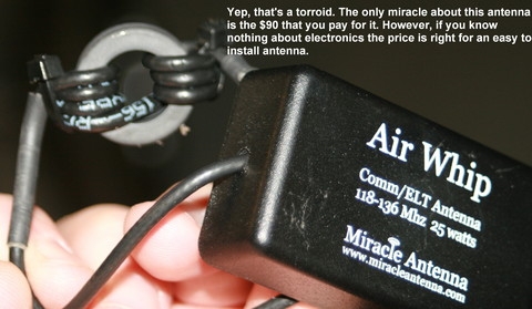
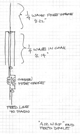
anyone has come to an elegant end-fed dipole in
the airplanes was the Miracle Antenna brand
"air-whip", end-feed dipole antenna with the
toroidal common mode choke we discussed earlier
this past week.
[img]cid:.0[/img]
[img]cid:.1[/img]
You could string this style antenna out under a
leading edge but you still have to deal with the common-
mode choke 'lump' . . .
I note that Miracle Antennas seems to have
closed the doors. Aircraft Spruce doesn't offer
the antennas any more and the website is black.
They were in business for a lot of years and ejoyed
some good reviews by their ham-radio clients.
It seems that their demise is based more on business
issues than product performance issues.
The big problem with development of the
lead edge vor antenna is the inconvenient
packaging process that involves cut-n-try
experiments on a device buried under
layers of Fiberglas.
It follows that what ever lies underneath that
layer of glass and epoxy should be a low-risk
configuration . . . it's damned hard to change
if you don't like it.
This seems like an ideal application for an active
antenna. This is a relatively short (on the order of
6 to 12 inches long attached to a very compact
amplifier right at the end of the coax feedline.
It takes a little fussing to get dc voltage out
to the amplifier on the coax but this could well
be a VERY compact solution to a receive-only antenna
for VOR that eliminates the geometry issues that
arise when you try to put a center fed dipole into
a leading edge.
Bob . . .
| | - The Matronics AeroElectric-List Email Forum - | | | Use the List Feature Navigator to browse the many List utilities available such as the Email Subscriptions page, Archive Search & Download, 7-Day Browse, Chat, FAQ, Photoshare, and much more:
http://www.matronics.com/Navigator?AeroElectric-List |
|
| Description: |
|
| Filesize: |
73.85 KB |
| Viewed: |
4738 Time(s) |

|
| Description: |
|
| Filesize: |
91.69 KB |
| Viewed: |
4738 Time(s) |
|
|
|
| Back to top |
|
|
jluckey(at)pacbell.net
Guest
|
| Posted: Mon Oct 27, 2014 12:01 pm Post subject: Toroid beads/VOR antenna design |
|
|
You may already be aware but thought I would mention it - Have you read Bob Archer's stuff on antennas? I think is company is called Sportcraft Antennas. A quick google should find his website.
FYI,
-Jeff
On Monday, October 27, 2014 12:37 PM, "Robert L. Nuckolls, III" <nuckolls.bob(at)aeroelectric.com> wrote:
At 09:47 2014-10-27, you wrote:
| Quote: | --> AeroElectric-List message posted by: <berkut13(at)berkut13.com>
Thanks! Very helpful discussion. Yes, the ferrites are for future COM antennas being imbedded in composite structure where size does matter.
The below brings up a different question I have about a retrofit VOR/GS antenna I need to install as well: A traditional 'T' shaped (with a slight angle in the two radials) VOR antenna can not be utilized given the physical constraints of the area it must be installed. There are really no other options for mounting given the aircraft's shape and construction materials. The two radials for the antenna will be in-line, no angle, horizontal and mounted in a newly formed conduit drilled into the leading edge foam of a small airfoil skinned with fiberglass. The radials will likely be solid conductor wire or copper foil attached to a small wooden dowel for rigidity during installation and soldered to the coax. I plan to construct a balun out of coax as described below. This part is all rather straightforward. |
Any 'morphing' of geometry from the center-fed
dipole driven with coax at right angles will
result in a degradation of performance in terms
of pattern and impedance matching. The closest
anyone has come to an elegant end-fed dipole in
the airplanes was the Miracle Antenna brand
"air-whip", end-feed dipole antenna with the
toroidal common mode choke we discussed earlier
this past week.
[img]cid:1.659687060(at)web184906.mail.gq1.yahoo.com[/img]
[img]cid:2.659687060(at)web184906.mail.gq1.yahoo.com[/img]
You could string this style antenna out under a
leading edge but you still have to deal with the common-
mode choke 'lump' . . .
I note that Miracle Antennas seems to have
closed the doors. Aircraft Spruce doesn't offer
the antennas any more and the website is black.
They were in business for a lot of years and ejoyed
some good reviews by their ham-radio clients.
It seems that their demise is based more on business
issues than product performance issues.
The big problem with development of the
lead edge vor antenna is the inconvenient
packaging process that involves cut-n-try
experiments on a device buried under
layers of Fiberglas.
It follows that what ever lies underneath that
layer of glass and epoxy should be a low-risk
configuration . . . it's damned hard to change
if you don't like it.
This seems like an ideal application for an active
antenna. This is a relatively short (on the order of
6 to 12 inches long attached to a very compact
amplifier right at the end of the coax feedline.
It takes a little fussing to get dc voltage out
to the amplifier on the coax but this could well
be a VERY compact solution to a receive-only antenna
for VOR that eliminates the geometry issues that
arise when you try to put a center fed dipole into
a leading edge.
Bob . . .
| | - The Matronics AeroElectric-List Email Forum - | | | Use the List Feature Navigator to browse the many List utilities available such as the Email Subscriptions page, Archive Search & Download, 7-Day Browse, Chat, FAQ, Photoshare, and much more:
http://www.matronics.com/Navigator?AeroElectric-List |
|
| Description: |
|
| Filesize: |
73.85 KB |
| Viewed: |
4738 Time(s) |
|
| Description: |
|
| Filesize: |
91.69 KB |
| Viewed: |
4738 Time(s) |

|
|
|
| Back to top |
|
|
berkut13(at)berkut13.com
Guest
|
| Posted: Mon Oct 27, 2014 1:22 pm Post subject: Toroid beads/VOR antenna design |
|
|
Bob,
Based on what you have indicated, this type of “air whip” antenna would work very well in this area – small airfoil leading edge D-section (carbon spared, glass skinned canard in this case). I can feed the antenna portion of the assembly into the foam conduit and the choke can reside inside the fuselage area, either just outside the airfoil skin, or I can build a small access box for it. If an “active” box is required, electrical is readily available in this area too. All of this can be done without affecting the external airfoil surface and thus easy to implement and potentially to remove and service.
Can you point me to some more specific info on how to build this type of antenna and choke?
Thanks!
-James
From: Robert L. Nuckolls, III (nuckolls.bob(at)aeroelectric.com)
Sent: Monday, October 27, 2014 2:13 PM
To: aeroelectric-list(at)matronics.com (aeroelectric-list(at)matronics.com)
Subject: Re: Re: Toroid beads/VOR antenna design
At 09:47 2014-10-27, you wrote:
| Quote: | --> AeroElectric-List message posted by: <berkut13(at)berkut13.com>
The below brings up a different question I have about a retrofit VOR/GS antenna I need to install as well: A traditional 'T' shaped (with a slight angle in the two radials) VOR antenna can not be utilized given the physical constraints of the area it must be installed. |
"air-whip", end-feed dipole antenna with the
toroidal common mode choke we discussed earlier
this past week.
[img]cid:FF9923CCB41F469AA35A22968198A6F6(at)DEFIANT2600[/img]
You could string this style antenna out under a
leading edge but you still have to deal with the common-
mode choke 'lump' . . .
| | - The Matronics AeroElectric-List Email Forum - | | | Use the List Feature Navigator to browse the many List utilities available such as the Email Subscriptions page, Archive Search & Download, 7-Day Browse, Chat, FAQ, Photoshare, and much more:
http://www.matronics.com/Navigator?AeroElectric-List |
|
| Description: |
|
| Filesize: |
73.85 KB |
| Viewed: |
4736 Time(s) |

|
|
|
| Back to top |
|
|
nuckolls.bob(at)aeroelect
Guest
|
| Posted: Tue Oct 28, 2014 7:15 am Post subject: Toroid beads/VOR antenna design |
|
|
At 16:20 2014-10-27, you wrote:
| Quote: | Bob,
Based on what you have indicated, this type of
“air whip” antenna would work very well in
this area � small airfoil leading edge
D-section (carbon spared, glass skinned canard
in this case). I can feed the antenna portion
of the assembly into the foam conduit and the
choke can reside inside the fuselage area,
either just outside the airfoil skin, or I can
build a small access box for it. If an
“active” box is required, electrical is
readily available in this area too. All of this
can be done without affecting the external
airfoil surface and thus easy to implement and
potentially to remove and service.
Can you point me to some more specific info on
how to build this type of antenna and choke?
|
Not sure this is the best way to go. Assume you are
glassing a 'conduit' into the leading edge of the
surface under consideration. What is the inside diameter
of the proposed conduit? How long? Do I presume correctly
that the 'radio end' of the conduit is accessible after
assembly such that any antenna slipped into it could
be repaired/modified at a later time?
Bob . . .
| | - The Matronics AeroElectric-List Email Forum - | | | Use the List Feature Navigator to browse the many List utilities available such as the Email Subscriptions page, Archive Search & Download, 7-Day Browse, Chat, FAQ, Photoshare, and much more:
http://www.matronics.com/Navigator?AeroElectric-List |
|
|
|
| Back to top |
|
|
berkut13(at)berkut13.com
Guest
|
| Posted: Tue Oct 28, 2014 7:55 am Post subject: Toroid beads/VOR antenna design |
|
|
This is actually a retrofit as the original structure was built by the owner

without any VOR or GS antenna(s).  Horizontal, antenna space on this

aircraft is limited to this area only.


The hope is not to "glass" an antenna into/onto the structure, but to insert

one into a conduit that was bored into the internal foam (about 5/8"dia,

about 5ft long) of the leading edge D-section on one side of the canard.

The radio end would protrude from the structure into the nose of the

aircraft either as a coax connector, pig tail, or I can create an internal

box for a choke/circuitry/etc.   The original idea was to put a dipole in

this area as I described earlier, but it sounds like there would  too much

degradation in performance having the center feed coax+balun parallel and

very close to one of the elements.   Removal would simply be a reverse of

the insert - pull it out/stick it in with a little glass cut/repair at the

feed end.


I'm trying to avoid the traditional retrofit which is to glass (permanently)

a copper foil dipole onto the center bottom surface of the canard.  This too

is sub-optimal as the radials will extend onto the external airfoil surface,

the antenna is blocked/surrounded by rudder pedals/hydraulic

pump/relays/battery/etc and previous installations in this area have been

low performance.  The canard is carbon spared, so the traditional V shape of

the antenna is extremely flat (almost straight) anyway being limited to the

3.5" in front of the spar.    I have had good results with shallow V dipoles

in the hollow D-sections of molded canards with about 3" separation between

radials and coax run....but of course, that is not an option here.


Thoughts?


-James

--
| | - The Matronics AeroElectric-List Email Forum - | | | Use the List Feature Navigator to browse the many List utilities available such as the Email Subscriptions page, Archive Search & Download, 7-Day Browse, Chat, FAQ, Photoshare, and much more:
http://www.matronics.com/Navigator?AeroElectric-List |
|
|
|
| Back to top |
|
|
nuckolls.bob(at)aeroelect
Guest
|
| Posted: Tue Oct 28, 2014 12:26 pm Post subject: Toroid beads/VOR antenna design |
|
|
I'm trying to avoid the traditional retrofit which is to glass

(permanently) a copper foil dipole onto the center bottom surface of

the canard.  This too is sub-optimal as the radials will extend onto

the external airfoil surface, the antenna is blocked/surrounded by

rudder pedals/hydraulic pump/relays/battery/etc and previous

installations in this area have been low performance.  The canard is

carbon spared, so the traditional V shape of the antenna is extremely

flat (almost straight) anyway being limited to the 3.5" in front of

the spar.    I have had good results with shallow V dipoles in the

hollow D-sections of molded canards with about 3" separation between

radials and coax run....but of course, that is not an option here.


   The legacy "v" shape was more cosmetic than physically

   or electrically beneficial. The straight dipole in your

   leading edge would be just fine.


   I'm thinking about an "active" antenna. An electrically

   'short' antenna (less than 1/4 wave) can be an effective

   receiving antenna . . . but it's not resonant . . . meaning

   that the thing is a pretty hi impedance source of energy

   not well suited to piping that energy into a 50-ohm

   coax.


   A work-around has roots that go WWwaaayyy back in radio

   receiving history with earliest practical roots demonstrated

   in car radios. Antennas on cars might be little more than

   1 meter long yet expected to perform in the capture of

   signals having wavelengths in the neighborhood of 200-400

   meters.


   In the instance before us, it's quite possible to get

   a 'resonant' antenna capable of delivering energy into

   a 50-ohm coax . . . the problem is physical layout

   limits that we've discussed. But suppose we consider a

   'short' antenna . . . say about 1/10th wavelength at

   115 Mhz or 10" long.


   A simple amplifier can be crafted to go on the antenna

   end of the coax that will improve the short antenna's

   ability to deliver energy into the coax.  It takes about

   8 components on a board about 1/2 x 3/4 inch. You not

   only run your normal RG coax out to this board, you run

   a 22AWG wire connected to 14V.


   Now your overall antenna is less than a foot long and

   doesn't need the "counter-poise" that turns a 1/4

   wave monopole into a dipole of twice the length.


   I've got some other antenna work to do in the next few

   weeks and I thought I would fiddle with an active

   antenna amplifier for VOR/LOC/GS. Could you bore a hole

   in your canard leading edge foam to accept a 1" piece

   of thinwall pvc pipe about 15" long?  If so, we may

   well be able to craft an antenna that would slip into

   the pipe and just lay there.

   Bob . . .
| | - The Matronics AeroElectric-List Email Forum - | | | Use the List Feature Navigator to browse the many List utilities available such as the Email Subscriptions page, Archive Search & Download, 7-Day Browse, Chat, FAQ, Photoshare, and much more:
http://www.matronics.com/Navigator?AeroElectric-List |
|
|
|
| Back to top |
|
|
berkut13(at)berkut13.com
Guest
|
| Posted: Tue Oct 28, 2014 3:07 pm Post subject: Toroid beads/VOR antenna design |
|
|
A small, active antenna is just fine as I would have room for a circuit

board on the end of the whip (inboard end) and have power available a few

inches away.


I don’t think I can get 1"dia in there.  The D section is quite small in

aspect, and there are wooden dowels running fore/aft in the middle of the

foam from the construction process - I had to bore in front of those.  The

foam conduit already exists now, I bored it from the tip inboard.  I will

plug/repair the outboard conduit hole in the tip, and although it could be

used for initial installation, I would not consider it to be an access or

service point in the future as it would affect the external surfacing/paint.


In this case, and ideally, the antenna portion would be flexible enough to

bend 90degrees (not sharply) to be fed down and into the foam conduit

(inboard to outboard) -  it is not a direct shot into the conduit from the

inboard end.  There is a plunge cut box in the bottom inboard skin/foam for

access to the LE foam conduit.  This area will also will be the exit point

for the antenna pigtail/connection.  The antenna would just lay in the foam

conduit, and the circuit board can be supported or secured in the access box

area.


If you anticipate working on an antenna design as you describe, I will table

this issue for a few weeks and move forward with other items.  I am working

to get this particular aircraft in the air in the Dec'14/Jan'15 timeframe

and am on track to do so.   Obviously, it can’t fly until the holes in the

canard are repaired (preferably with antenna installed).


So you know, the antenna will be connected to a Garmin 650 radio that has a

VOR/GS splitter internally and has only the one coax connection.


Thanks for all your help!

-James

--
| | - The Matronics AeroElectric-List Email Forum - | | | Use the List Feature Navigator to browse the many List utilities available such as the Email Subscriptions page, Archive Search & Download, 7-Day Browse, Chat, FAQ, Photoshare, and much more:
http://www.matronics.com/Navigator?AeroElectric-List |
|
|
|
| Back to top |
|
|
nuckolls.bob(at)aeroelect
Guest
|
| Posted: Wed Oct 29, 2014 7:30 am Post subject: Toroid beads/VOR antenna design |
|
|
At 18:01 2014-10-28, you wrote:
| Quote: | --> AeroElectric-List message posted by: <berkut13(at)berkut13.com>
A small, active antenna is just fine as I would have room for a circuit board on the end of the whip (inboard end) and have power available a few inches away.
I don’t think I can get 1"dia in there. The D section is quite small in aspect, and there are wooden dowels running fore/aft in the middle of the foam from the construction process. |
I'm not sure I have a clear mental image of your configuration.
Q: If the antenna portion of the proposed installation were
a 15-25" long, say stiff rod with the 'amplifier' stuck to
the inboard end, would you be able to install such a device?
It occurs to me that while many builders have described the
boring of a hole through the foam under a composite structure,
it might be possible to simply push the antenna portion of
the device into the foam. The resulting hole would be no
larger than what the antenna itself produced.
| Quote: | | In this case, and ideally, the antenna portion would be flexible enough to bend 90degrees (not sharply) to be fed down and into the foam conduit (inboard to outboard) - it is not a direct shot into the conduit from the inboard end. |
This is the unclear part. The 'antenna' portion the
system need not be straight, rigid or any particular
shape. It ultimately DOES want to have some geometric
length in the horizontal plane (this is the e-field probe
portion of its physics) but something of a curve or zig-zag
isn't especially detrimental.
So the goal is to get SOME conductor in a mostly horizontal
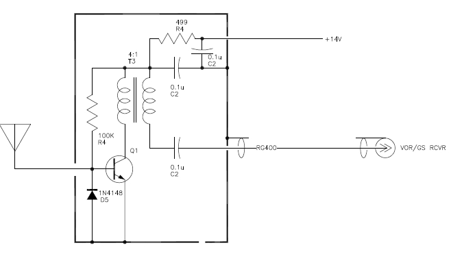
orientation. The 'active' portion of the installation is
an etched circuit board with a handful of surface mount
components on it. I'm thinking something on the order of
3/4" square. It would be fitted with a length of RG coax
and a 14v power supply wire soldered on. The antenna connection
could be a short pigtail that attached to the end of
the conductor of choice installed in the foam.
[img]cid:.0[/img]
| Quote: | | So you know, the antenna will be connected to a Garmin 650 radio that has a VOR/GS splitter internally and has only the one coax connection. |
This is a 'broadband' design which should perform
well at both VOR/LOC and GS frequencies. Parts
not already on hand have been ordered. I'm going
to set up a little 'antenna range' experiment in
the back yard in the next few weeks. I can massage
this active antenna project at the same time.
Bob . . .
| | - The Matronics AeroElectric-List Email Forum - | | | Use the List Feature Navigator to browse the many List utilities available such as the Email Subscriptions page, Archive Search & Download, 7-Day Browse, Chat, FAQ, Photoshare, and much more:
http://www.matronics.com/Navigator?AeroElectric-List |
|
| Description: |
|
| Filesize: |
36.76 KB |
| Viewed: |
4711 Time(s) |
|
|
|
| Back to top |
|
|
berkut13(at)berkut13.com
Guest
|
| Posted: Wed Oct 29, 2014 10:42 am Post subject: Toroid beads/VOR antenna design |
|
|
Again, thank you for your help here.
I have private emailed you with some photos of the project’s canard to help better describe the mounting challenges. For everyone else – just imagine a surf board laying on the floor (perpendicular) in front of you, mark off a 2’ wide section in the center, and you need to install a horizontal antenna into the long side edge of board left or right of the center section; you can only access that center section you just marked off, and you can’t violate the external surfaces other than the center section. Fun, eh?
Had I to do it over with this new antenna style in mind...yes, a ridged rod could be inserted into the foam (at a slight angle from horizontal) but it would need to have a spade point on the end, and be able to be chucked into a drill while inserting for the length you are describing. The standard blue foam is easy to penetrate an inch or two, but beyond that the friction builds rapidly. This would be quite difficult if the amp was attached to the element. It would be much easier to just use a slightly larger dia rod with a spade tip to bore a path through the skin and into the foam for the antenna to be inserted into later – again, at a slight angle from horizontal.
-James
From: Robert L. Nuckolls, III (nuckolls.bob(at)aeroelectric.com)
Sent: Wednesday, October 29, 2014 10:29 AM
To: aeroelectric-list(at)matronics.com (aeroelectric-list(at)matronics.com)
Subject: Re: Re: Toroid beads/VOR antenna design
At 18:01 2014-10-28, you wrote:
| Quote: | --> AeroElectric-List message posted by: <berkut13(at)berkut13.com>
A small, active antenna is just fine as I would have room for a circuit board on the end of the whip (inboard end) and have power available a few inches away.
I donât think I can get 1"dia in there. The D section is quite small in aspect, and there are wooden dowels running fore/aft in the middle of the foam from the construction process. |
I'm not sure I have a clear mental image of your configuration.
Q: If the antenna portion of the proposed installation were
a 15-25" long, say stiff rod with the 'amplifier' stuck to
the inboard end, would you be able to install such a device?
[quote][b]
| | - The Matronics AeroElectric-List Email Forum - | | | Use the List Feature Navigator to browse the many List utilities available such as the Email Subscriptions page, Archive Search & Download, 7-Day Browse, Chat, FAQ, Photoshare, and much more:
http://www.matronics.com/Navigator?AeroElectric-List |
|
|
|
| Back to top |
|
|
|
|
You cannot post new topics in this forum
You cannot reply to topics in this forum
You cannot edit your posts in this forum
You cannot delete your posts in this forum
You cannot vote in polls in this forum
You cannot attach files in this forum
You can download files in this forum
|
Powered by phpBB © 2001, 2005 phpBB Group
|

