 |
Matronics Email Lists
Web Forum Interface to the Matronics Email Lists
|
| View previous topic :: View next topic |
| Author |
Message |
ceengland7(at)gmail.com
Guest
|
 Posted: Sun Jul 26, 2015 11:13 am Post subject: ARINC 429 wiring practices Posted: Sun Jul 26, 2015 11:13 am Post subject: ARINC 429 wiring practices |
 |
|
I'm in the process of wiring my panel, which includes an old Garmin 430 (non-WAAS), an AFS AF4500S EFIS, AFS ARINC module, and AFS Pilot autopilot. I'm using the AF3000-4000 Installation Guide, v7.4. Looking through the AFS docs, their wiring diagrams are a bit...inconsistent... on how to treat the ARINC and serial port data wiring.Â
So I did some digging in the InterWebs to find the 'proper' way to wire ARINC 429 stuff. Two different sources say to ground the ARINC 429 Â shield at source, destination, and at every 'break point' where additional receivers are added, in daisy chain fashion. Easy enough; I can handle that.Â
There are 3 ARINC data runs between the ARINC module and the 430. Should each get its own shielded twisted pair, or would it be kosher to run 3 pairs in one shielded cable (and/or variations on that theme)?
In various places, there are both single and bi-directional serial runs between/among the EFIS, 430, and other devices. In one case, they specify that a ground return *isn't needed* (obviously depending on system ground(s) between the EFIS & the 430). In most cases, they show a separate ground return wire, *within* the shield of the cable. Now, I'd understand that if the serial lines were 'balanced' (floating return), but all the serial ground returns are electrically bonded to the chassis of the AF4500S. Any noise imposed on the shield goes to exactly the same place inside the unit as the separate ground return. Seems silly to run an extra ground wire that's at the same potential as the shield.
Any thoughts on this from those who have either designed or done the actual work on a/c using ARINC 429 and/or serial port technology?
Thanks,
Charlie
[quote][b]
| | - The Matronics AeroElectric-List Email Forum - | | | Use the List Feature Navigator to browse the many List utilities available such as the Email Subscriptions page, Archive Search & Download, 7-Day Browse, Chat, FAQ, Photoshare, and much more:
http://www.matronics.com/Navigator?AeroElectric-List |
|
|
|
| Back to top |
|
 |
rv8iator(at)gmail.com
Guest
|
| Posted: Mon Jul 27, 2015 6:18 am Post subject: ARINC 429 wiring practices |
|
|
Hello Charlie,
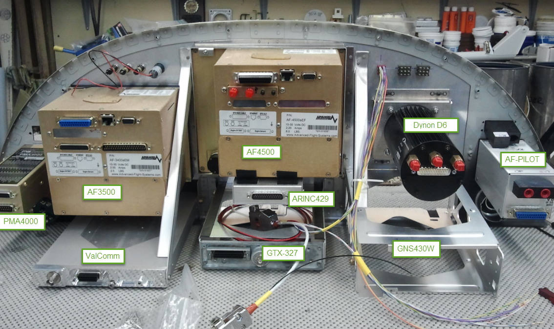
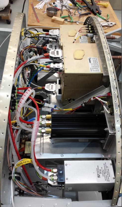
My -8 panel is holds a 430W, AF4500, ARINC module, AF3500 and AF-pilot.
I followed the AFS wiring schematic exactly. No shielded cables except for the run to the magnetometer and serial port connections. All remaining connections between the ARINC 429 module, the 430 and the AF4500 are AWG22 single wire bundled into a harness with zip ties. Â
I attached the ARINC 429 box to the underside of the AF4500 with self adhering velcro. Thus all signal wire runs are short, less than 24 inches.
System works flawlessly. Â
[img]cid:ii_14ecfd370fb563ec[/img]
[img]cid:ii_14ecfd7d06404a00[/img]
Chris Stone
RV-8
80802
On Sun, Jul 26, 2015 at 12:11 PM, Charlie England <ceengland7(at)gmail.com (ceengland7(at)gmail.com)> wrote:
| Quote: | I'm in the process of wiring my panel, which includes an old Garmin 430 (non-WAAS), an AFS AF4500S EFIS, AFS ARINC module, and AFS Pilot autopilot. I'm using the AF3000-4000 Installation Guide, v7.4. Looking through the AFS docs, their wiring diagrams are a bit...inconsistent... on how to treat the ARINC and serial port data wiring.Â
So I did some digging in the InterWebs to find the 'proper' way to wire ARINC 429 stuff. Two different sources say to ground the ARINC 429 Â shield at source, destination, and at every 'break point' where additional receivers are added, in daisy chain fashion. Easy enough; I can handle that.Â
There are 3 ARINC data runs between the ARINC module and the 430. Should each get its own shielded twisted pair, or would it be kosher to run 3 pairs in one shielded cable (and/or variations on that theme)?
In various places, there are both single and bi-directional serial runs between/among the EFIS, 430, and other devices. In one case, they specify that a ground return *isn't needed* (obviously depending on system ground(s) between the EFIS & the 430). In most cases, they show a separate ground return wire, *within* the shield of the cable. Now, I'd understand that if the serial lines were 'balanced' (floating return), but all the serial ground returns are electrically bonded to the chassis of the AF4500S. Any noise imposed on the shield goes to exactly the same place inside the unit as the separate ground return. Seems silly to run an extra ground wire that's at the same potential as the shield.
Any thoughts on this from those who have either designed or done the actual work on a/c using ARINC 429 and/or serial port technology?
Thanks,
Charlie
| Quote: |
ist" target="_blank">http://www.matronics.com/Navigator?AeroElectric-List
tp://forums.matronics.com
_blank">http://www.matronics.com/contribution
|
|
| | - The Matronics AeroElectric-List Email Forum - | | | Use the List Feature Navigator to browse the many List utilities available such as the Email Subscriptions page, Archive Search & Download, 7-Day Browse, Chat, FAQ, Photoshare, and much more:
http://www.matronics.com/Navigator?AeroElectric-List |
|
| Description: |
|
| Filesize: |
1.28 MB |
| Viewed: |
7072 Time(s) |
|
| Description: |
|
| Filesize: |
769.68 KB |
| Viewed: |
7072 Time(s) |
|
|
|
| Back to top |
|
|
dlj04(at)josephson.com
Guest
|
| Posted: Mon Jul 27, 2015 7:10 am Post subject: ARINC 429 wiring practices |
|
|
I built nav processors for survey planes using several ARINC 429 devices

tied together. Twisted pair wire was sufficient although we used

shielded. Shielding for differential serial data like that is to reduce

electromagnetic interference (transmitted and received) among the other

systems, so tying the shield to chassis at one end should be fine. EMI

was the only place where we had problems, and in some cases we needed to

swap which end was shielded to get the quietest results. Some of our

signals used multiple pairs inside one shield and that worked fine. No

use for a separate ground wire.


David Josephson
| | - The Matronics AeroElectric-List Email Forum - | | | Use the List Feature Navigator to browse the many List utilities available such as the Email Subscriptions page, Archive Search & Download, 7-Day Browse, Chat, FAQ, Photoshare, and much more:
http://www.matronics.com/Navigator?AeroElectric-List |
|
|
|
| Back to top |
|
|
nuckolls.bob(at)aeroelect
Guest
|
| Posted: Mon Jul 27, 2015 7:24 am Post subject: ARINC 429 wiring practices |
|
|
| Quote: |
Any thoughts on this from those who have either designed or done the actual work on a/c using ARINC 429 and/or serial port technology?
|
ARINC 429 is implemented on aircraft of all
sizes wherein local grounds for appliances
can be yards apart and serial data is conducted
on wires that traverse the wild and wooly environs
for all manner of potential antagonist and victim.
The short story is that for a single-engine,
light aircraft with all the goodies mounted
on the panel and sharing local grounds, the
risks for loss of serial data signal integrity
are zero.
There is no value in adding any sort of ground
external to a shielded-twisted-pair . . . why
anyone would suggest such at thing is a mystery.
There is no value in grounding a shield at both
ends . . . shields on STP data lines are just that,
stop-gaps for electrostatically coupled noises
into or out of the lines which are already
protected by the physics of twisted, balanced
signal paths. Telephone companies have successfully
exploited this particular physics in the fabrication
and operation of phone lines in bundles with
hundreds of other signals and traversing horrible
environs over many miles.
The twisted, balanced pair is about as bullet
proof as you can get without shielding. Ground
the shields at either end and only once.
Bob . . . [quote][b]
| | - The Matronics AeroElectric-List Email Forum - | | | Use the List Feature Navigator to browse the many List utilities available such as the Email Subscriptions page, Archive Search & Download, 7-Day Browse, Chat, FAQ, Photoshare, and much more:
http://www.matronics.com/Navigator?AeroElectric-List |
|
|
|
| Back to top |
|
|
ceengland7(at)gmail.com
Guest
|
| Posted: Mon Jul 27, 2015 11:57 am Post subject: ARINC 429 wiring practices |
|
|
Thanks for the pics. I suspected that the elaborate shielding described in the ARINC docs was a bit of overkill, but I went ahead with actual shielded twisted pair. I'm about 75% done at this point; should have waited a couple of days. 
Charlie
On Mon, Jul 27, 2015 at 9:16 AM, Christopher Cee Stone <rv8iator(at)gmail.com (rv8iator(at)gmail.com)> wrote:
[quote]Hello Charlie,
My -8 panel is holds a 430W, AF4500, ARINC module, AF3500 and AF-pilot.
I followed the AFS wiring schematic exactly. No shielded cables except for the run to the magnetometer and serial port connections. All remaining connections between the ARINC 429 module, the 430 and the AF4500 are AWG22 single wire bundled into a harness with zip ties. Â
I attached the ARINC 429 box to the underside of the AF4500 with self adhering velcro. Thus all signal wire runs are short, less than 24 inches.
System works flawlessly. Â
Chris Stone
RV-8
80802
On Sun, Jul 26, 2015 at 12:11 PM, Charlie England <ceengland7(at)gmail.com (ceengland7(at)gmail.com)> wrote:
| Quote: | I'm in the process of wiring my panel, which includes an old Garmin 430 (non-WAAS), an AFS AF4500S EFIS, AFS ARINC module, and AFS Pilot autopilot. I'm using the AF3000-4000 Installation Guide, v7.4. Looking through the AFS docs, their wiring diagrams are a bit...inconsistent.. on how to treat the ARINC and serial port data wiring.Â
So I did some digging in the InterWebs to find the 'proper' way to wire ARINC 429 stuff. Two different sources say to ground the ARINC 429 Â shield at source, destination, and at every 'break point' where additional receivers are added, in daisy chain fashion. Easy enough; I can handle that.Â
There are 3 ARINC data runs between the ARINC module and the 430. Should each get its own shielded twisted pair, or would it be kosher to run 3 pairs in one shielded cable (and/or variations on that theme)?
In various places, there are both single and bi-directional serial runs between/among the EFIS, 430, and other devices. In one case, they specify that a ground return *isn't needed* (obviously depending on system ground(s) between the EFIS & the 430). In most cases, they show a separate ground return wire, *within* the shield of the cable. Now, I'd understand that if the serial lines were 'balanced' (floating return), but all the serial ground returns are electrically bonded to the chassis of the AF4500S. Any noise imposed on the shield goes to exactly the same place inside the unit as the separate ground return. Seems silly to run an extra ground wire that's at the same potential as the shield.
Any thoughts on this from those who have either designed or done the actual work on a/c using ARINC 429 and/or serial port technology?
Thanks,
Charlie
|
[b]
| | - The Matronics AeroElectric-List Email Forum - | | | Use the List Feature Navigator to browse the many List utilities available such as the Email Subscriptions page, Archive Search & Download, 7-Day Browse, Chat, FAQ, Photoshare, and much more:
http://www.matronics.com/Navigator?AeroElectric-List |
|
|
|
| Back to top |
|
|
ceengland7(at)gmail.com
Guest
|
| Posted: Mon Jul 27, 2015 1:36 pm Post subject: ARINC 429 wiring practices |
|
|
Thanks to David & Bob.Â
Bob,
My question about the 'extra' ground wire was related to the serial port(s), not ARINC. IIRC, serial stuff is typically unbalanced, with a signal line and a shield/ground return. In the case of the AFS docs, they show in one case (to external GPS) a pair of signal wires (bi-directional data), and a ground wire, all wrapped in a shield. In another case (magnetometer) they show a pair of RS422 signal wires, a power wire, and a ground wire, all wrapped in a shield. That's the practice of embedding an extra ground wire inside a shield (when the shield can serve as ground) that I was really questioning.
Charlie
On Mon, Jul 27, 2015 at 10:23 AM, Robert L. Nuckolls, III <nuckolls.bob(at)aeroelectric.com (nuckolls.bob(at)aeroelectric.com)> wrote:
[quote] | Quote: |
Any thoughts on this from those who have either designed or done the actual work on a/c using ARINC 429 and/or serial port technology?
|
  ARINC 429 is implemented on aircraft of all
  sizes wherein local grounds for appliances
  can be yards apart and serial data is conducted
  on wires that traverse the wild and wooly environs
  for all manner of potential antagonist and victim.
  The short story is that for a single-engine,
  light aircraft with all the goodies mounted
  on the panel and sharing local grounds, the
  risks for loss of serial data signal integrity
  are zero.
  There is no value in adding any sort of ground
  external to a shielded-twisted-pair . . . why
  anyone would suggest such at thing is a mystery.
  There is no value in grounding a shield at both
  ends . . . shields on STP data lines are just that,
  stop-gaps for electrostatically coupled noises
  into or out of the lines which are already
  protected by the physics of twisted, balanced
  signal paths. Telephone companies have successfully
  exploited this particular physics in the fabrication
  and operation of phone lines in bundles with
  hundreds of other signals and traversing horrible
  environs over many miles.
  The twisted, balanced pair is about as bullet
  proof as you can get without shielding. Ground
  the shields at either end and only once.
 Bob . . . | Quote: |
ist" target="_blank">http://www.matronics.com/Navigator?AeroElectric-List
tp://forums.matronics.com
_blank">http://www.matronics.com/contribution
|
[b]
| | - The Matronics AeroElectric-List Email Forum - | | | Use the List Feature Navigator to browse the many List utilities available such as the Email Subscriptions page, Archive Search & Download, 7-Day Browse, Chat, FAQ, Photoshare, and much more:
http://www.matronics.com/Navigator?AeroElectric-List |
|
|
|
| Back to top |
|
|
nuckolls.bob(at)aeroelect
Guest
|
| Posted: Thu Jul 30, 2015 5:49 am Post subject: ARINC 429 wiring practices |
|
|
At 04:34 PM 7/27/2015, you wrote:
Thanks to David & Bob.Â
Bob,
My question about the 'extra' ground wire was related to the serial port(s), not ARINC. IIRC, serial stuff is typically unbalanced, with a signal line and a shield/ground return. In the case of the AFS docs, they show in one case (to external GPS) a pair of signal wires (bi-directional data), and a ground wire, all wrapped in a shield. In another case (magnetometer) they show a pair of RS422 signal wires, a power wire, and a ground wire, all wrapped in a shield. That's the practice of embedding an extra ground wire inside a shield (when the shield can serve as ground) that I was really questioning.
The 'extra' wire you're describing . . . is it bare?
. . . and what is the nature of the shield material?
. . . what you are describing is reminiscent
of a product from Belden Wire called "Beldfoil"
shielded wire. Instead of braiding strands of wire
over the bundle, they wrap an aluminum foil shield
over it. VERY effective shielding but electrical
connection to thin aluminum is hard to make up.
The solution was to bundle a bare stranded wire
in with the other wires. Given that it is not
insulated, it makes connection with the shielding
at innumerable places along the length of the cable.
http://tinyurl.com/nhpjmup
Given that electro-static shield currents are
very low, it matters not that the ground connection
to the foil is not gas-tight. Hence, the shield ground
has a hi order of integrity to the task and the foil
shielding is electro-statically superior and much
less expensive than braid . . . a kind of win-win.
Unfortunately, this technology is not generally
offered in combination with our favorite insulations
so you don't see this wire used in TC or military
aircraft . . . but it's fine for our purposes.
That 'extra' wire CAN be used as a part of the
power path as long as it's 22AWG current ratings
are observed . . . with the caveat that the
return path power wire be included in the bundle
so that you get parallel path cancellation for
electro-magnetic coupling. But as a general rule,
you're almost never wrong to use the shield
for electro-static decoupling and attach it
to ground one time only at either end.
Bob . . . [quote][b]
| | - The Matronics AeroElectric-List Email Forum - | | | Use the List Feature Navigator to browse the many List utilities available such as the Email Subscriptions page, Archive Search & Download, 7-Day Browse, Chat, FAQ, Photoshare, and much more:
http://www.matronics.com/Navigator?AeroElectric-List |
|
|
|
| Back to top |
|
|
ceengland7(at)gmail.com
Guest
|
| Posted: Thu Jul 30, 2015 11:48 am Post subject: ARINC 429 wiring practices |
|
|
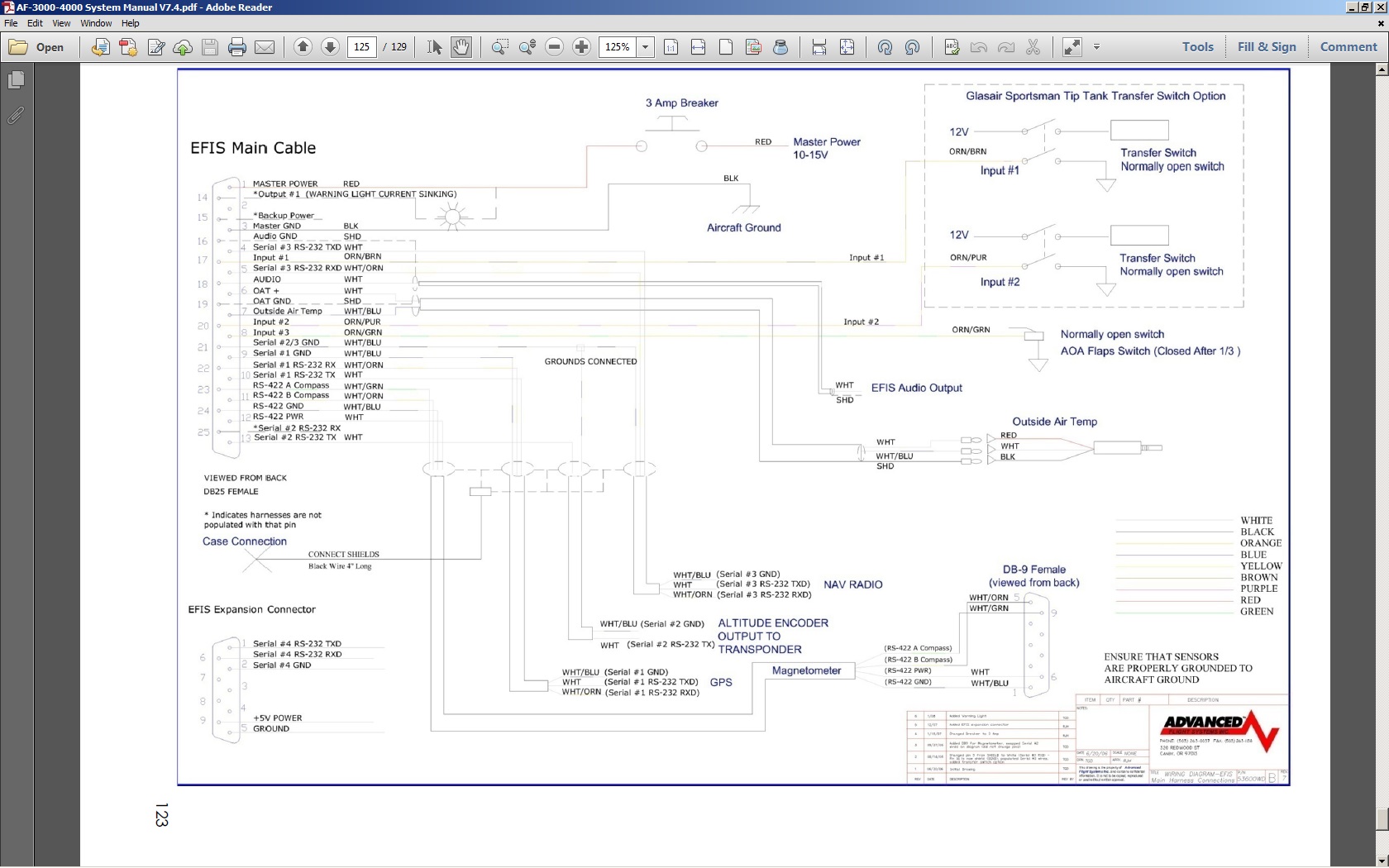
Understand about Belfoil shielded wire; I've built my share of cables using it in one of my previous lives as a sound engineer & audio tech. It's unrelated to my question. As a reminder, my question is about the AFS *documents*, not actual wire. I should have attached an image of the diagram with the 1st post. Image attached now.
See the wiring from the 'EFIS Main Cable' connector to the Nav Radio, Altitude Encoder Output to Transponder, GPS, and Magnetometer. All are shown with a separate ground wire, drawn within the shield. None of the devices draw significant current, and all the 'ground' return pins shown in the EFIS Main Connector are electrically common to the chassis of the EFIS itself. My question is about the 'extra' ground wire, drawn within the shield for each of these destinations.
The only connection that does make sense to me is the 'EFIS Audio Output', which logically shows a signal wire and a shield return, without the extra ground wire.
On Thu, Jul 30, 2015 at 8:48 AM, Robert L. Nuckolls, III <nuckolls.bob(at)aeroelectric.com (nuckolls.bob(at)aeroelectric.com)> wrote:
| Quote: | At 04:34 PM 7/27/2015, you wrote:
Thanks to David & Bob.Ã
Bob,
My question about the 'extra' ground wire was related to the serial port(s), not ARINC. IIRC, serial stuff is typically unbalanced, with a signal line and a shield/ground return. In the case of the AFS docs, they show in one case (to external GPS) a pair of signal wires (bi-directional data), and a ground wire, all wrapped in a shield. In another case (magnetometer) they show a pair of RS422 signal wires, a power wire, and a ground wire, all wrapped in a shield. That's the practice of embedding an extra ground wire inside a shield (when the shield can serve as ground) that I was really questioning.
 The 'extra' wire you're describing . . . is it bare?
 . . . and what is the nature of the shield material?
 . . . what you are describing is reminiscent
 of a product from Belden Wire called "Beldfoil"
 shielded wire. Instead of braiding strands of wire
 over the bundle, they wrap an aluminum foil shield
 over it. VERY effective shielding but electrical
 connection to thin aluminum is hard to make up.
 The solution was to bundle a bare stranded wire
 in with the other wires. Given that it is not
 insulated, it makes connection with the shielding
 at innumerable places along the length of the cable.
http://tinyurl.com/nhpjmup
 Given that electro-static shield currents are
 very low, it matters not that the ground connection
 to the foil is not gas-tight. Hence, the shield ground
 has a hi order of integrity to the task and the foil
 shielding is electro-statically superior and much
 less expensive than braid . . . a kind of win-win.
 Unfortunately, this technology is not generally
 offered in combination with our favorite insulations
 so you don't see this wire used in TC or military
 aircraft . . . but it's fine for our purposes.
 That 'extra' wire CAN be used as a part of the
 power path as long as it's 22AWG current ratings
 are observed . . . with the caveat that the
 return path power wire be included in the bundle
 so that you get parallel path cancellation for
 electro-magnetic coupling. But as a general rule,
 you're almost never wrong to use the shield
 for electro-static decoupling and attach it
 to ground one time only at either end.
 Bob . . . | Quote: |
ist" target="_blank">http://www.matronics.com/Navigator?AeroElectric-List
tp://forums.matronics.com
_blank">http://www.matronics.com/contribution
|
|
| | - The Matronics AeroElectric-List Email Forum - | | | Use the List Feature Navigator to browse the many List utilities available such as the Email Subscriptions page, Archive Search & Download, 7-Day Browse, Chat, FAQ, Photoshare, and much more:
http://www.matronics.com/Navigator?AeroElectric-List |
|
| Description: |
|
| Filesize: |
305.67 KB |
| Viewed: |
7021 Time(s) |
|
|
|
| Back to top |
|
|
rossmickey(at)comcast.net
Guest
|
| Posted: Thu Jul 30, 2015 12:50 pm Post subject: ARINC 429 wiring practices |
|
|
I just got done installing a 5600. I wired it as shown. Each Serial Port bundle has a RX, TX, Gnd and shield. The shields for the four ports are all connected together at the main harness connector with a black wire coming out of the connector that gets grounded to the chassis.   I used whatever TX, RX wires I needed for the particular instrument.  I ran all of the Gnd wires to my ground block since that is where all of my instruments are grounded. Everything works great ever since I got rid of the 18â length of unused OAT cable.Â
If your question is why they want us to ground each serial port, I canât tell you. I just did it. Have you called AFS and asked them?
Ross
N9PT
From: owner-aeroelectric-list-server(at)matronics.com [mailto:owner-aeroelectric-list-server(at)matronics.com] On Behalf Of Charlie England
Sent: Thursday, July 30, 2015 12:47 PM
To: aeroelectric-list(at)matronics.com
Subject: Re: ARINC 429 wiring practices
Understand about Belfoil shielded wire; I've built my share of cables using it in one of my previous lives as a sound engineer & audio tech. It's unrelated to my question. As a reminder, my question is about the AFS *documents*, not actual wire. I should have attached an image of the diagram with the 1st post. Image attached now.
See the wiring from the 'EFIS Main Cable' connector to the Nav Radio, Altitude Encoder Output to Transponder, GPS, and Magnetometer. All are shown with a separate ground wire, drawn within the shield. None of the devices draw significant current, and all the 'ground' return pins shown in the EFIS Main Connector are electrically common to the chassis of the EFIS itself. My question is about the 'extra' ground wire, drawn within the shield for each of these destinations.
The only connection that does make sense to me is the 'EFIS Audio Output', which logically shows a signal wire and a shield return, without the extra ground wire.
On Thu, Jul 30, 2015 at 8:48 AM, Robert L. Nuckolls, III <nuckolls.bob(at)aeroelectric.com (nuckolls.bob(at)aeroelectric.com)> wrote: | Quote: |
At 04:34 PM 7/27/2015, you wrote:
Thanks to David & Bob.Ã
Bob,
My question about the 'extra' ground wire was related to the serial port(s), not ARINC. IIRC, serial stuff is typically unbalanced, with a signal line and a shield/ground return. In the case of the AFS docs, they show in one case (to external GPS) a pair of signal wires (bi-directional data), and a ground wire, all wrapped in a shield. In another case (magnetometer) they show a pair of RS422 signal wires, a power wire, and a ground wire, all wrapped in a shield. That's the practice of embedding an extra ground wire inside a shield (when the shield can serve as ground) that I was really questioning.
The 'extra' wire you're describing . . . is it bare?
. . . and what is the nature of the shield material?
. . . what you are describing is reminiscent
of a product from Belden Wire called "Beldfoil"
shielded wire. Instead of braiding strands of wire
over the bundle, they wrap an aluminum foil shield
over it. VERY effective shielding but electrical
connection to thin aluminum is hard to make up.
The solution was to bundle a bare stranded wire
in with the other wires. Given that it is not
insulated, it makes connection with the shielding
at innumerable places along the length of the cable.
http://tinyurl.com/nhpjmup
Given that electro-static shield currents are
very low, it matters not that the ground connection
to the foil is not gas-tight. Hence, the shield ground
has a hi order of integrity to the task and the foil
shielding is electro-statically superior and much
less expensive than braid . . . a kind of win-win.
Unfortunately, this technology is not generally
offered in combination with our favorite insulations
so you don't see this wire used in TC or military
aircraft . . . but it's fine for our purposes.
That 'extra' wire CAN be used as a part of the
power path as long as it's 22AWG current ratings
are observed . . . with the caveat that the
return path power wire be included in the bundle
so that you get parallel path cancellation for
electro-magnetic coupling. But as a general rule,
you're almost never wrong to use the shield
for electro-static decoupling and attach it
to ground one time only at either end.
Bob . . .
|
[quote][b]
| | - The Matronics AeroElectric-List Email Forum - | | | Use the List Feature Navigator to browse the many List utilities available such as the Email Subscriptions page, Archive Search & Download, 7-Day Browse, Chat, FAQ, Photoshare, and much more:
http://www.matronics.com/Navigator?AeroElectric-List |
|
|
|
| Back to top |
|
|
ceengland7(at)gmail.com
Guest
|
| Posted: Thu Jul 30, 2015 1:32 pm Post subject: ARINC 429 wiring practices |
|
|
I haven't asked them yet, because I already have a strong suspicion of what their answer will be: 'to shield the ground from noise'. Serial data needs a ground return, but since the ground return pins in the connector are all bonded to the case of the EFIS, any noise on the shield is also on those ground return pins. Which begs the question: why have the extra ground wire? My suspicion is that they are following some 'certified aircraft' practice that was started back in mythological times and hasn't been updated with current knowledge. That's why I've been asking here; we've seen other 'stuff' in certified a/c that can be done better or simpler, based on current knowledge.
Glad to hear that you've got yours working noise-free.
Charlie
Â
On Thu, Jul 30, 2015 at 3:48 PM, Ross Home <rossmickey(at)comcast.net (rossmickey(at)comcast.net)> wrote:
[quote]
I just got done installing a 5600. I wired it as shown. Each Serial Port bundle has a RX, TX, Gnd and shield. The shields for the four ports are all connected together at the main harness connector with a black wire coming out of the connector that gets grounded to the chassis.   I used whatever TX, RX wires I needed for the particular instrument. I ran all of the Gnd wires to my ground block since that is where all of my instruments are grounded. Everything works great ever since I got rid of the 18â length of unused OAT cable.Â
Â
If your question is why they want us to ground each serial port, I canât tell you. I just did it. Have you called AFS and asked them?
Â
Ross
N9PT
Â
From: owner-aeroelectric-list-server(at)matronics.com (owner-aeroelectric-list-server(at)matronics.com) [mailto:owner-aeroelectric-list-server(at)matronics.com (owner-aeroelectric-list-server(at)matronics.com)] On Behalf Of Charlie England
Sent: Thursday, July 30, 2015 12:47 PM
To: aeroelectric-list(at)matronics.com (aeroelectric-list(at)matronics.com)
Subject: Re: ARINC 429 wiring practices
Â
Understand about Belfoil shielded wire; I've built my share of cables using it in one of my previous lives as a sound engineer & audio tech. It's unrelated to my question. As a reminder, my question is about the AFS *documents*, not actual wire. I should have attached an image of the diagram with the 1st post. Image attached now.
Â
See the wiring from the 'EFIS Main Cable' connector to the Nav Radio, Altitude Encoder Output to Transponder, GPS, and Magnetometer. All are shown with a separate ground wire, drawn within the shield. None of the devices draw significant current, and all the 'ground' return pins shown in the EFIS Main Connector are electrically common to the chassis of the EFIS itself. My question is about the 'extra' ground wire, drawn within the shield for each of these destinations.
Â
The only connection that does make sense to me is the 'EFIS Audio Output', which logically shows a signal wire and a shield return, without the extra ground wire.
Â
On Thu, Jul 30, 2015 at 8:48 AM, Robert L. Nuckolls, III <nuckolls.bob(at)aeroelectric.com (nuckolls.bob(at)aeroelectric.com)> wrote: | Quote: |
At 04:34 PM 7/27/2015, you wrote:
Thanks to David & Bob.Ã
Bob,
My question about the 'extra' ground wire was related to the serial port(s), not ARINC. IIRC, serial stuff is typically unbalanced, with a signal line and a shield/ground return. In the case of the AFS docs, they show in one case (to external GPS) a pair of signal wires (bi-directional data), and a ground wire, all wrapped in a shield. In another case (magnetometer) they show a pair of RS422 signal wires, a power wire, and a ground wire, all wrapped in a shield. That's the practice of embedding an extra ground wire inside a shield (when the shield can serve as ground) that I was really questioning.
 The 'extra' wire you're describing . . . is it bare?
 . . . and what is the nature of the shield material?
 . . . what you are describing is reminiscent
 of a product from Belden Wire called "Beldfoil"
 shielded wire. Instead of braiding strands of wire
 over the bundle, they wrap an aluminum foil shield
 over it. VERY effective shielding but electrical
 connection to thin aluminum is hard to make up.
 The solution was to bundle a bare stranded wire
 in with the other wires. Given that it is not
 insulated, it makes connection with the shielding
 at innumerable places along the length of the cable.
http://tinyurl.com/nhpjmup
 Given that electro-static shield currents are
 very low, it matters not that the ground connection
 to the foil is not gas-tight. Hence, the shield ground
 has a hi order of integrity to the task and the foil
 shielding is electro-statically superior and much
 less expensive than braid . . . a kind of win-win.
 Unfortunately, this technology is not generally
 offered in combination with our favorite insulations
 so you don't see this wire used in TC or military
 aircraft . . . but it's fine for our purposes.
 That 'extra' wire CAN be used as a part of the
 power path as long as it's 22AWG current ratings
 are observed . . . with the caveat that the
 return path power wire be included in the bundle
 so that you get parallel path cancellation for
 electro-magnetic coupling. But as a general rule,
 you're almost never wrong to use the shield
 for electro-static decoupling and attach it
 to ground one time only at either end.
 Bob . . .
|
Â
| Quote: |
ist" target="_blank">http://www.matronics.com/Navigator?AeroElectric-List
tp://forums.matronics.com
_blank">http://www.matronics.com/contribution
|
[b]
| | - The Matronics AeroElectric-List Email Forum - | | | Use the List Feature Navigator to browse the many List utilities available such as the Email Subscriptions page, Archive Search & Download, 7-Day Browse, Chat, FAQ, Photoshare, and much more:
http://www.matronics.com/Navigator?AeroElectric-List |
|
|
|
| Back to top |
|
|
|
|
You cannot post new topics in this forum
You cannot reply to topics in this forum
You cannot edit your posts in this forum
You cannot delete your posts in this forum
You cannot vote in polls in this forum
You cannot attach files in this forum
You can download files in this forum
|
Powered by phpBB © 2001, 2005 phpBB Group
|

