 |
Matronics Email Lists
Web Forum Interface to the Matronics Email Lists
|
| View previous topic :: View next topic |
| Author |
Message |
trigo(at)mail.telepac.pt
Guest
|
 Posted: Fri Apr 15, 2016 9:06 am Post subject: CAN Bus wiring Posted: Fri Apr 15, 2016 9:06 am Post subject: CAN Bus wiring |
 |
|
In the installation of a Garmin G3X system, to interconnect the various components you have to build a network called CAN Bus, similar to the system created by BOSCH for the automotive industry.
I cannot find, in the Garmin installation manual, how to physically build this network.
In some interconnect drawings (for example to connect the autopilot servos) they show the CAN wires going in and out of the connectors, therefore in this case I suppose I have to crimp 2 wires in the same pin.
But in other drawings ( to connect to the AHARS or the Displays) they show a node connection, which I am wondering how to make it.
So, can anyone who knows how to do it, or already did it, please explain how do I physically connect the 2-wires shielded cables to obtain a correctly built CAN bus backbone.
Best
Carlos
 Sem vÃrus. www.avast.com Sem vÃrus. www.avast.com
| | - The Matronics AeroElectric-List Email Forum - | | | Use the List Feature Navigator to browse the many List utilities available such as the Email Subscriptions page, Archive Search & Download, 7-Day Browse, Chat, FAQ, Photoshare, and much more:
http://www.matronics.com/Navigator?AeroElectric-List |
|
|
|
| Back to top |
|
 |
gilles.thesee(at)free.fr
Guest
|
| Posted: Fri Apr 15, 2016 9:39 am Post subject: CAN Bus wiring |
|
|
Le 15/04/2016 19:04, Carlos Trigo a écrit :
| Quote: | <![endif]--> <![endif]-->
But in other drawings ( to connect to the AHARS or the Displays) they show a node connection, which I am wondering how to make it.
|
Hi Carlos,
How about some SubD connectors ?
https://en.wikipedia.org/wiki/CAN_bus
FWIW
--
Best regards,
Gilles
http://contrails.free.fr
http://lapierre.skunkworks.free.fr
| | - The Matronics AeroElectric-List Email Forum - | | | Use the List Feature Navigator to browse the many List utilities available such as the Email Subscriptions page, Archive Search & Download, 7-Day Browse, Chat, FAQ, Photoshare, and much more:
http://www.matronics.com/Navigator?AeroElectric-List |
|
|
|
| Back to top |
|
|
enginerdy(at)gmail.com
Guest
|
| Posted: Fri Apr 15, 2016 9:56 am Post subject: CAN Bus wiring |
|
|
You can get really fancy and try to fab up some kind of tap-off connector, but generally you just need to make sure the stub length of the tap wires is relatively small (ie just a few inches or less)
Considering that CANBus requires termination, Iâm surprised they donât give very specific guidance on how to install it.
| | - The Matronics AeroElectric-List Email Forum - | | | Use the List Feature Navigator to browse the many List utilities available such as the Email Subscriptions page, Archive Search & Download, 7-Day Browse, Chat, FAQ, Photoshare, and much more:
http://www.matronics.com/Navigator?AeroElectric-List |
|
|
|
| Back to top |
|
|
ceengland7(at)gmail.com
Guest
|
| Posted: Fri Apr 15, 2016 10:01 am Post subject: CAN Bus wiring |
|
|
On 4/15/2016 12:04 PM, Carlos Trigo wrote:
| Quote: | <![endif]--> <![endif]-->
In the installation of a Garmin G3X system, to interconnect the various components you have to build a network called CAN Bus, similar to the system created by BOSCH for the automotive industry.
Â
I cannot find, in the Garmin installation manual, how to physically build this network.
In some interconnect drawings (for example to connect the autopilot servos) they show the CAN wires going in and out of the connectors, therefore in this case I suppose I have to crimp 2 wires in the same pin.
But in other drawings ( to connect to the AHARS or the Displays) they show a node connection, which I am wondering how to make it.
Â
So, can anyone who knows how to do it, or already did it, please explain how do I physically connect the 2-wires shielded cables to obtain a correctly built CAN bus backbone.
Â
Best
CarlosÂ
|
Carlos,
I've never needed to know a lot about CAN bus architecture, but my gut reaction is that since it's stone cold reliable in cars, so it's probably neither expensive or difficult to implement.
https://en.wikipedia.org/wiki/CAN_bus
Above says that it's wiring architecture-agnostic (can be bus, star or mix of both). I did a little reading & it seems that unless you're in a very high electrical noise environment, shielding probably isn't even needed. Twisted pairs and termination resistors are recommended, however. If you use a short 'stub' wire out of each connector, and crimp your two wires onto that stub, you have created, well, literally, a very short *stub* from the bus backbone to that node. Note that the drawings on the Wiki page don't depict a shield. If you do use a shield, you should be able to use the techniques in 'the book' to keep continuity in the backbone shield & realize that a 4" (or even a foot long) unshielded stub isn't going to hurt.
FWIW,
Charlie
| | - The Matronics AeroElectric-List Email Forum - | | | Use the List Feature Navigator to browse the many List utilities available such as the Email Subscriptions page, Archive Search & Download, 7-Day Browse, Chat, FAQ, Photoshare, and much more:
http://www.matronics.com/Navigator?AeroElectric-List |
|
|
|
| Back to top |
|
|
matronics(at)rtist.nl
Guest
|
| Posted: Fri Apr 15, 2016 10:25 am Post subject: CAN Bus wiring |
|
|
Hi Carlos,
CAN bus attaches all systems in parallel on a 2-wire bus. Each node/system has a CAN-Hi and a CAN-Lo pin. As you already found, each pin has two wires in the same pin, one coming from the previous node and one going to the next node. The first and the last node on the string have a terminating resistor that you can place externally onto the cable, or when the node offers one internally, by adding a jumper inside the last connector.
Not sure which AHRS drawings you are looking at, but some nodes offer other bus connections like RS-232 or RS-485. Is that what confused you?
Rob
On 4/15/2016 7:04 PM, Carlos Trigo wrote:
| Quote: | <![endif]--> <![endif]-->
In the installation of a Garmin G3X system, to interconnect the various components you have to build a network called CAN Bus, similar to the system created by BOSCH for the automotive industry.
Â
I cannot find, in the Garmin installation manual, how to physically build this network.
In some interconnect drawings (for example to connect the autopilot servos) they show the CAN wires going in and out of the connectors, therefore in this case I suppose I have to crimp 2 wires in the same pin.
But in other drawings ( to connect to the AHARS or the Displays) they show a node connection, which I am wondering how to make it.
Â
So, can anyone who knows how to do it, or already did it, please explain how do I physically connect the 2-wires shielded cables to obtain a correctly built CAN bus backbone.
Â
Best
CarlosÂ
Â
Â
Â
Â
Â
Â
Sem vÃrus. www.avast.com |
| | - The Matronics AeroElectric-List Email Forum - | | | Use the List Feature Navigator to browse the many List utilities available such as the Email Subscriptions page, Archive Search & Download, 7-Day Browse, Chat, FAQ, Photoshare, and much more:
http://www.matronics.com/Navigator?AeroElectric-List |
|
|
|
| Back to top |
|
|
trigo(at)mail.telepac.pt
Guest
|
| Posted: Fri Apr 15, 2016 11:03 am Post subject: CAN Bus wiring |
|
|
Hi Rob
I did understand that the CAN bus attaches all items in parallel on a 2-wire cable.
I also understood that there are terminators to be put in the first and last nodes.
My problem is with the intermediate nodes!
In the case of the servos (please see the 1st  attached pdf), I suppose that I will have to crimp 2 wires (in and out) in the same pin, thus making the continuity.
But in the case of connecting the GSU 25 (AHARS) with the Display units (GDU 46X/37X) - please see the 2nd attached pdf, in which the CAN bus is connected thru nodes inserted in the middle of the 2-wire cable - thatâs where I donât know how to physically make those connections.
Should I strip a small length of the each wire and make a pigtail with a solder sleeve?
Thanks
CarlosÂ
From: owner-aeroelectric-list-server(at)matronics.com [mailto:owner-aeroelectric-list-server(at)matronics.com] On Behalf Of Rob Turk
Sent: sexta-feira, 15 de Abril de 2016 19:22
To: aeroelectric-list(at)matronics.com
Subject: Re: CAN Bus wiring
Hi Carlos,
CAN bus attaches all systems in parallel on a 2-wire bus. Each node/system has a CAN-Hi and a CAN-Lo pin. As you already found, each pin has two wires in the same pin, one coming from the previous node and one going to the next node. The first and the last node on the string have a terminating resistor that you can place externally onto the cable, or when the node offers one internally, by adding a jumper inside the last connector.
Not sure which AHRS drawings you are looking at, but some nodes offer other bus connections like RS-232 or RS-485. Is that what confused you?
Rob
On 4/15/2016 7:04 PM, Carlos Trigo wrote:
| Quote: |
In the installation of a Garmin G3X system, to interconnect the various components you have to build a network called CAN Bus, similar to the system created by BOSCH for the automotive industry.
I cannot find, in the Garmin installation manual, how to physically build this network.
In some interconnect drawings (for example to connect the autopilot servos) they show the CAN wires going in and out of the connectors, therefore in this case I suppose I have to crimp 2 wires in the same pin.
But in other drawings ( to connect to the AHARS or the Displays) they show a node connection, which I am wondering how to make it.
So, can anyone who knows how to do it, or already did it, please explain how do I physically connect the 2-wires shielded cables to obtain a correctly built CAN bus backbone.
Best
Carlos
Sem vÃrus. www.avast.com |
Sem vÃrus. www.avast.com
| | - The Matronics AeroElectric-List Email Forum - | | | Use the List Feature Navigator to browse the many List utilities available such as the Email Subscriptions page, Archive Search & Download, 7-Day Browse, Chat, FAQ, Photoshare, and much more:
http://www.matronics.com/Navigator?AeroElectric-List |
|
| Description: |
|

Download |
| Filename: |
Servos_wiring.pdf |
| Filesize: |
212.01 KB |
| Downloaded: |
490 Time(s) |
| Description: |
|
Download |
| Filename: |
AHARS_(GSU_25)_wiring_to_the_Displays.pdf |
| Filesize: |
119.88 KB |
| Downloaded: |
580 Time(s) |
|
|
| Back to top |
|
|
rick(at)beebe.org
Guest
|
| Posted: Fri Apr 15, 2016 11:24 am Post subject: CAN Bus wiring |
|
|
You can wire it the same as the servos. For example, Pin 46 of the 2nd GDU would have a wire from pin 46 of the first GDU and a second wire heading either to the 3rd GDU or to pin 1 of the GSU. It's functionally the same as using little stub wires.
--Rick
On 04/15/2016 02:59 PM, Carlos Trigo wrote:
| Quote: | v\:* {behavior:url(#default#VML);} o\:* {behavior:url(#default#VML);} w\:* {behavior:url(#default#VML);} .shape {behavior:url(#default#VML);} <![endif]--> <![endif]--> <![endif]-->
Hi Rob
Â
I did understand that the CAN bus attaches all items in parallel on a 2-wire cable.
I also understood that there are terminators to be put in the first and last nodes.
My problem is with the intermediate nodes!
Â
In the case of the servos (please see the 1st  attached pdf), I suppose that I will have to crimp 2 wires (in and out) in the same pin, thus making the continuity.
Â
But in the case of connecting the GSU 25 (AHARS) with the Display units (GDU 46X/37X) - please see the 2nd attached pdf, in which the CAN bus is connected thru nodes inserted in the middle of the 2-wire cable - thatâs where I donât know how to physically make those connections.
Should I strip a small length of the each wire and make a pigtail with a solder sleeve?
Â
Thanks
CarlosÂ
Â
Â
Â
Â
Â
From: owner-aeroelectric-list-server(at)matronics.com (owner-aeroelectric-list-server(at)matronics.com) [mailto:owner-aeroelectric-list-server(at)matronics.com (owner-aeroelectric-list-server(at)matronics.com)] On Behalf Of Rob Turk
Sent: sexta-feira, 15 de Abril de 2016 19:22
To: aeroelectric-list(at)matronics.com (aeroelectric-list(at)matronics.com)
Subject: Re: CAN Bus wiring
Â
Hi Carlos,
CAN bus attaches all systems in parallel on a 2-wire bus. Each node/system has a CAN-Hi and a CAN-Lo pin. As you already found, each pin has two wires in the same pin, one coming from the previous node and one going to the next node. The first and the last node on the string have a terminating resistor that you can place externally onto the cable, or when the node offers one internally, by adding a jumper inside the last connector.
Not sure which AHRS drawings you are looking at, but some nodes offer other bus connections like RS-232 or RS-485. Is that what confused you?
Rob
On 4/15/2016 7:04 PM, Carlos Trigo wrote:
| Quote: |
In the installation of a Garmin G3X system, to interconnect the various components you have to build a network called CAN Bus, similar to the system created by BOSCH for the automotive industry.
Â
I cannot find, in the Garmin installation manual, how to physically build this network.
In some interconnect drawings (for example to connect the autopilot servos) they show the CAN wires going in and out of the connectors, therefore in this case I suppose I have to crimp 2 wires in the same pin.
But in other drawings ( to connect to the AHARS or the Displays) they show a node connection, which I am wondering how to make it.
Â
So, can anyone who knows how to do it, or already did it, please explain how do I physically connect the 2-wires shielded cables to obtain a correctly built CAN bus backbone.
Â
Best
CarlosÂ
Â
Â
Â
Â
Â
Â
Â
Sem vÃrus. www.avast.com |
Â
Sem vÃrus. www.avast.com |
| | - The Matronics AeroElectric-List Email Forum - | | | Use the List Feature Navigator to browse the many List utilities available such as the Email Subscriptions page, Archive Search & Download, 7-Day Browse, Chat, FAQ, Photoshare, and much more:
http://www.matronics.com/Navigator?AeroElectric-List |
|
|
|
| Back to top |
|
|
clr(at)redingaviation.com
Guest
|
| Posted: Fri Apr 15, 2016 11:47 am Post subject: CAN Bus wiring |
|
|
Carlos
Don't know if you have seen some of the YouTube videos by SteinAir. He has some great videos on using solder sleeves and making up terminals.
I just finished wiring up my panel which is a G3x system using the info from Steins videos and the cartoons from Bob on splicing two wires together at a pin.
Keep your can bus runs as short as possible if you are not using shielded wires and make sure that you use the termination at the end of the run and you should be fine
Craig
On Apr 15, 2016, at 14:22, Rob Turk <matronics(at)rtist.nl (matronics(at)rtist.nl)> wrote:
| Quote: | Hi Carlos,
CAN bus attaches all systems in parallel on a 2-wire bus. Each node/system has a CAN-Hi and a CAN-Lo pin. As you already found, each pin has two wires in the same pin, one coming from the previous node and one going to the next node. The first and the last node on the string have a terminating resistor that you can place externally onto the cable, or when the node offers one internally, by adding a jumper inside the last connector.
Not sure which AHRS drawings you are looking at, but some nodes offer other bus connections like RS-232 or RS-485. Is that what confused you?
Rob
On 4/15/2016 7:04 PM, Carlos Trigo wrote:
| Quote: | <![endif]--> <![endif]-->
In the installation of a Garmin G3X system, to interconnect the various components you have to build a network called CAN Bus, similar to the system created by BOSCH for the automotive industry.
I cannot find, in the Garmin installation manual, how to physically build this network.
In some interconnect drawings (for example to connect the autopilot servos) they show the CAN wires going in and out of the connectors, therefore in this case I suppose I have to crimp 2 wires in the same pin.
But in other drawings ( to connect to the AHARS or the Displays) they show a node connection, which I am wondering how to make it.
So, can anyone who knows how to do it, or already did it, please explain how do I physically connect the 2-wires shielded cables to obtain a correctly built CAN bus backbone.
Best
Carlos
Sem vÃrus. [/url][url=http://www.avast.com]www.avast.com |
|
| | - The Matronics AeroElectric-List Email Forum - | | | Use the List Feature Navigator to browse the many List utilities available such as the Email Subscriptions page, Archive Search & Download, 7-Day Browse, Chat, FAQ, Photoshare, and much more:
http://www.matronics.com/Navigator?AeroElectric-List |
|
|
|
| Back to top |
|
|
matronics(at)rtist.nl
Guest
|
| Posted: Fri Apr 15, 2016 11:52 am Post subject: CAN Bus wiring |
|
|
Hi Carlos,
On the second drawing you can use the same method of putting two wires in a single pin, this will be a valid CAN bus connection. That is the 'clean' option.
However, this is a big connector with lots of tightly spaced pins. Fitting two wires in each pin and connecting the shields may be a bit difficult inside the connector cap. Therefor you can also use the alternative of two small pieces of wire (a stub) and splice the CAN bus to attach those two wires. It is equally valid for CAN bus, as long as you keep the stub short (5 - 10 cm or so). Not as clean but equally valid.
Rob
On 4/15/2016 8:59 PM, Carlos Trigo wrote:
| Quote: | v\:* {behavior:url(#default#VML);} o\:* {behavior:url(#default#VML);} w\:* {behavior:url(#default#VML);} .shape {behavior:url(#default#VML);} <![endif]--> <![endif]--> <![endif]-->
Hi Rob
Â
I did understand that the CAN bus attaches all items in parallel on a 2-wire cable.
I also understood that there are terminators to be put in the first and last nodes.
My problem is with the intermediate nodes!
Â
In the case of the servos (please see the 1st  attached pdf), I suppose that I will have to crimp 2 wires (in and out) in the same pin, thus making the continuity.
Â
But in the case of connecting the GSU 25 (AHARS) with the Display units (GDU 46X/37X) - please see the 2nd attached pdf, in which the CAN bus is connected thru nodes inserted in the middle of the 2-wire cable - thatâs where I donât know how to physically make those connections.
Should I strip a small length of the each wire and make a pigtail with a solder sleeve?
Â
Thanks
CarlosÂ
Â
Â
Â
Â
Â
From: owner-aeroelectric-list-server(at)matronics.com (owner-aeroelectric-list-server(at)matronics.com) [mailto:owner-aeroelectric-list-server(at)matronics.com (owner-aeroelectric-list-server(at)matronics.com)] On Behalf Of Rob Turk
Sent: sexta-feira, 15 de Abril de 2016 19:22
To: aeroelectric-list(at)matronics.com (aeroelectric-list(at)matronics.com)
Subject: Re: CAN Bus wiring
Â
Hi Carlos,
CAN bus attaches all systems in parallel on a 2-wire bus. Each node/system has a CAN-Hi and a CAN-Lo pin. As you already found, each pin has two wires in the same pin, one coming from the previous node and one going to the next node. The first and the last node on the string have a terminating resistor that you can place externally onto the cable, or when the node offers one internally, by adding a jumper inside the last connector.
Not sure which AHRS drawings you are looking at, but some nodes offer other bus connections like RS-232 or RS-485. Is that what confused you?
Rob
On 4/15/2016 7:04 PM, Carlos Trigo wrote:
| Quote: |
In the installation of a Garmin G3X system, to interconnect the various components you have to build a network called CAN Bus, similar to the system created by BOSCH for the automotive industry.
Â
I cannot find, in the Garmin installation manual, how to physically build this network.
In some interconnect drawings (for example to connect the autopilot servos) they show the CAN wires going in and out of the connectors, therefore in this case I suppose I have to crimp 2 wires in the same pin.
But in other drawings ( to connect to the AHARS or the Displays) they show a node connection, which I am wondering how to make it.
Â
So, can anyone who knows how to do it, or already did it, please explain how do I physically connect the 2-wires shielded cables to obtain a correctly built CAN bus backbone.
Â
Best
CarlosÂ
Â
Â
Â
Â
Â
Â
Â
Sem vÃrus. www.avast.com |
Â
Sem vÃrus. www.avast.com |
| | - The Matronics AeroElectric-List Email Forum - | | | Use the List Feature Navigator to browse the many List utilities available such as the Email Subscriptions page, Archive Search & Download, 7-Day Browse, Chat, FAQ, Photoshare, and much more:
http://www.matronics.com/Navigator?AeroElectric-List |
|
|
|
| Back to top |
|
|
ceengland7(at)gmail.com
Guest
|
| Posted: Fri Apr 15, 2016 12:16 pm Post subject: CAN Bus wiring |
|
|
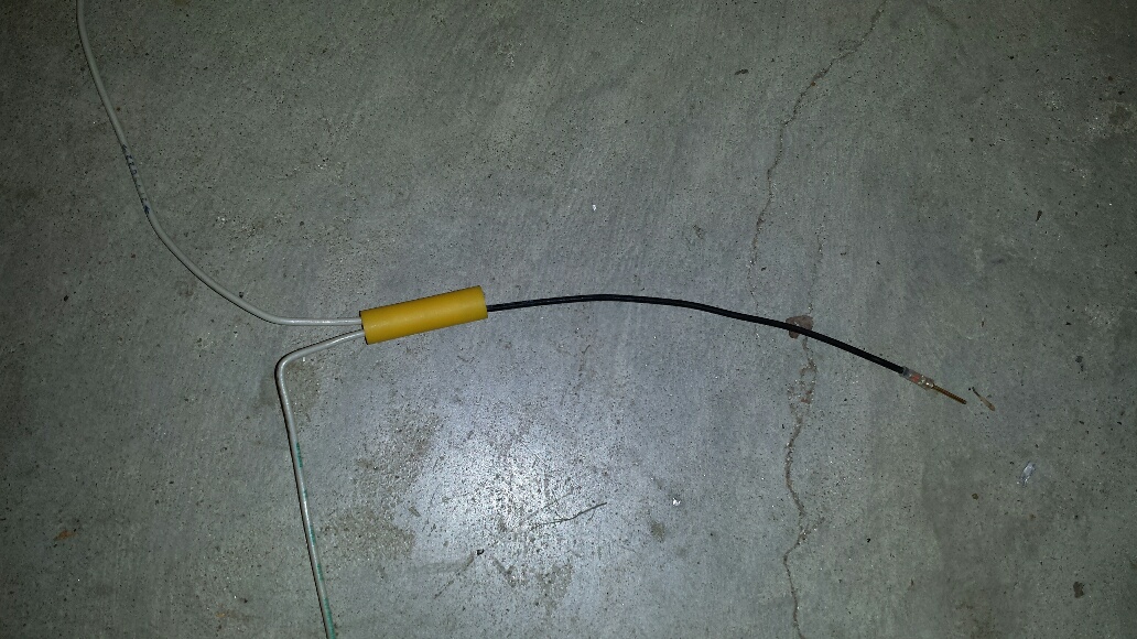
Quick & dirty pic of what I mentioned earlier as a 'stub'. Ignore colors; I just grabbed what was convenient to get the pic.Â
Crimp or solder the 'stub' in one end of a butt splice (yellow in pic); apply your required pin to the other end. Cut into the bus backbone, and snip one of the wires in the pair. Insert *both* of the clipped wire ends into the other end of the butt splice.Â
Repeat for the other wire in the pair.
Assuming you've kept the shield on the backbone, if you can cut into the cable without actually cutting the shield (yes, it can almost always be done), then tape it up & you're done. If not, or you want a cleaner look, manage the shield as shown in Bob's book, with insulated stubs on each shield with a butt splice on the shield stubs. The shield does not need to enter the node's connector.
Charlie
| | - The Matronics AeroElectric-List Email Forum - | | | Use the List Feature Navigator to browse the many List utilities available such as the Email Subscriptions page, Archive Search & Download, 7-Day Browse, Chat, FAQ, Photoshare, and much more:
http://www.matronics.com/Navigator?AeroElectric-List |
|
| Description: |
|
| Filesize: |
279.58 KB |
| Viewed: |
4671 Time(s) |
|
|
|
| Back to top |
|
|
trigo(at)mail.telepac.pt
Guest
|
| Posted: Fri Apr 15, 2016 4:08 pm Post subject: CAN Bus wiring |
|
|
Thank you Charlie
and Rob, Craig and Rick
Now I have a bunch of solutions to my problem.
Cheers
Carlos
Enviado do meu iPhone
No dia 15/04/2016, Ã s 21:12, Charlie England <ceengland7(at)gmail.com> escreveu:
| Quote: | Quick & dirty pic of what I mentioned earlier as a 'stub'. Ignore colors; I just grabbed what was convenient to get the pic.
Crimp or solder the 'stub' in one end of a butt splice (yellow in pic); apply your required pin to the other end. Cut into the bus backbone, and snip one of the wires in the pair. Insert *both* of the clipped wire ends into the other end of the butt splice.
Repeat for the other wire in the pair.
Assuming you've kept the shield on the backbone, if you can cut into the cable without actually cutting the shield (yes, it can almost always be done), then tape it up & you're done. If not, or you want a cleaner look, manage the shield as shown in Bob's book, with insulated stubs on each shield with a butt splice on the shield stubs. The shield does not need to enter the node's connector.
Charlie
<20160415_150157_resized.jpg>
|
| | - The Matronics AeroElectric-List Email Forum - | | | Use the List Feature Navigator to browse the many List utilities available such as the Email Subscriptions page, Archive Search & Download, 7-Day Browse, Chat, FAQ, Photoshare, and much more:
http://www.matronics.com/Navigator?AeroElectric-List |
|
|
|
| Back to top |
|
|
|
|
You cannot post new topics in this forum
You cannot reply to topics in this forum
You cannot edit your posts in this forum
You cannot delete your posts in this forum
You cannot vote in polls in this forum
You cannot attach files in this forum
You can download files in this forum
|
Powered by phpBB © 2001, 2005 phpBB Group
|

