 |
Matronics Email Lists
Web Forum Interface to the Matronics Email Lists
|
| View previous topic :: View next topic |
| Author |
Message |
gilles.thesee(at)free.fr
Guest
|
 Posted: Sat Dec 08, 2018 9:47 am Post subject: Bob Archer comm antenna dimensions ? Posted: Sat Dec 08, 2018 9:47 am Post subject: Bob Archer comm antenna dimensions ? |
 |
|
Hi all,

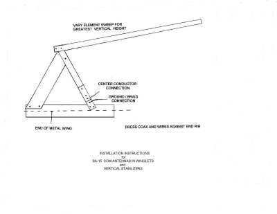
Some 15 years ago we ordered a Bob Archer comm antenna for       installation in our wingtip, and have been very satisfied with it.

Here is a sketch of our 15 year old antenna :


[img]cid:part1.300707EA.6D7F4BA4(at)free.fr[/img]


A buddy of mine launches into another project and just received a       new Archer antenna to install in his tail fin, but the dimensions       and shape seem different, and the rivets prevent the upper segment       from being swept up to fit into the tail.


Although the antenna is labelled "Comm", we are finally not sure       the model is a VHF one.


Does any of you gentlemen have any information as to the shape       and dimensions of the present time Archer comm antennas - or VOR       antennas - so we could clarify the matter ?


Thanks in advance,


          --

       Best regards,

       Gilles

       http://contrails.free.fr

       http://lapierre.skunkworks.free.fr
| | - The Matronics AeroElectric-List Email Forum - | | | Use the List Feature Navigator to browse the many List utilities available such as the Email Subscriptions page, Archive Search & Download, 7-Day Browse, Chat, FAQ, Photoshare, and much more:
http://www.matronics.com/Navigator?AeroElectric-List |
|
| Description: |
|
| Filesize: |
25.23 KB |
| Viewed: |
3519 Time(s) |
|
|
|
| Back to top |
|
 |
ceengland7(at)gmail.com
Guest
|
 Posted: Sat Dec 08, 2018 10:47 am Post subject: Bob Archer comm antenna dimensions ? Posted: Sat Dec 08, 2018 10:47 am Post subject: Bob Archer comm antenna dimensions ? |
 |
|
On 12/8/2018 11:46 AM, GTH wrote:
| Quote: |
Hi all,
Some 15 years ago we ordered a Bob Archer comm antenna for installation in our wingtip, and have been very satisfied with it.
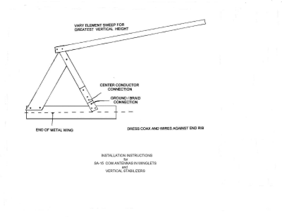
Here is a sketch of our 15 year old antenna :
[img]cid:part1.DD8677E2.27F3F3DA(at)gmail.com[/img]
A buddy of mine launches into another project and just received a new Archer antenna to install in his tail fin, but the dimensions and shape seem different, and the rivets prevent the upper segment from being swept up to fit into the tail.
Although the antenna is labelled "Comm", we are finally not sure the model is a VHF one.
Does any of you gentlemen have any information as to the shape and dimensions of the present time Archer comm antennas - or VOR antennas - so we could clarify the matter ?
Thanks in advance,
--
Best regards,
Gilles
http://contrails.free.fr
http://lapierre.skunkworks.free.fr
|
Pretty sure that if you could see side by side images of all the Sportcraft antennas, you'd see significant differences among the various antennas. IIRC, there are different models for RV-4-8, the -9, & -10 wing tips. The vertical fin would be yet another design. The VOR antennas would be yet another set.
Did he make sure that the model he bought is recommended for his a/c, and for the location where he intends to mount it?
Charlie
 Virus-free. www.avast.com [url=#DAB4FAD8-2DD7-40BB-A1B8-4E2AA1F9FDF2] [/url] Virus-free. www.avast.com [url=#DAB4FAD8-2DD7-40BB-A1B8-4E2AA1F9FDF2] [/url]
| | - The Matronics AeroElectric-List Email Forum - | | | Use the List Feature Navigator to browse the many List utilities available such as the Email Subscriptions page, Archive Search & Download, 7-Day Browse, Chat, FAQ, Photoshare, and much more:
http://www.matronics.com/Navigator?AeroElectric-List |
|
| Description: |
|
| Filesize: |
25.23 KB |
| Viewed: |
3518 Time(s) |
|
|
|
| Back to top |
|
 |
gilles.thesee(at)free.fr
Guest
|
 Posted: Sat Dec 08, 2018 11:38 am Post subject: Bob Archer comm antenna dimensions ? Posted: Sat Dec 08, 2018 11:38 am Post subject: Bob Archer comm antenna dimensions ? |
 |
|
Le 08/12/2018 à 19:49, Charlie England a écrit :
| Quote: | Pretty sure that if you could see side by side images of all the Sportcraft antennas, you'd see significant differences among the various antennas. IIRC, there are different models for RV-4-8, the -9, & -10 wing tips. The vertical fin would be yet another design. The VOR antennas would be yet another set.
Did he make sure that the model he bought is recommended for his a/c, and for the location where he intends to mount it?
|
Hi Charlie,
Thank you for responding.
His project is a composite homebuilt that certainly no one knows outside our country.
The antenna is to be located in the glass fiber fin, but as it is a small airplane, there no room for
a 1/2 wave antenna.
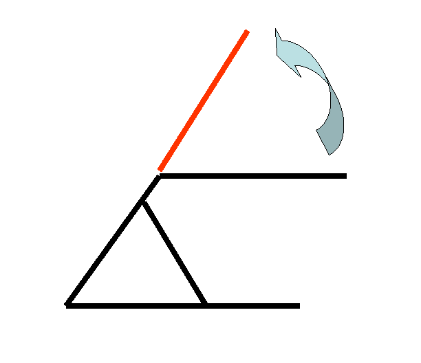
Provided the model is a correct comm antenna the actual question is, can we pivot the radiating element so as to match the fin, like in red in the following diagram
[img]cid:part1.258513B1.2B89A41E(at)free.fr[/img]
Of course this would involve removing some rivets, but from an electrical point of view, would such a "sweep" be acceptable ?
Thank you,
--
Best regards,
Gilles
http://contrails.free.fr
http://lapierre.skunkworks.free.fr
| | - The Matronics AeroElectric-List Email Forum - | | | Use the List Feature Navigator to browse the many List utilities available such as the Email Subscriptions page, Archive Search & Download, 7-Day Browse, Chat, FAQ, Photoshare, and much more:
http://www.matronics.com/Navigator?AeroElectric-List |
|
| Description: |
|
| Filesize: |
3.94 KB |
| Viewed: |
3517 Time(s) |
|
|
|
| Back to top |
|
 |
ceengland7(at)gmail.com
Guest
|
 Posted: Sat Dec 08, 2018 1:16 pm Post subject: Bob Archer comm antenna dimensions ? Posted: Sat Dec 08, 2018 1:16 pm Post subject: Bob Archer comm antenna dimensions ? |
 |
|
On Sat, Dec 8, 2018 at 1:42 PM GTH <gilles.thesee(at)free.fr (gilles.thesee(at)free.fr)> wrote:
| Quote: | Le 08/12/2018 à 19:49, Charlie England a écrit :
| Quote: | Pretty sure that if you could see side by side images of all the Sportcraft antennas, you'd see significant differences among the various antennas. IIRC, there are different models for RV-4-8, the -9, & -10 wing tips. The vertical fin would be yet another design. The VOR antennas would be yet another set.
Did he make sure that the model he bought is recommended for his a/c, and for the location where he intends to mount it?
|
Hi Charlie,
Thank you for responding.
His project is a composite homebuilt that certainly no one knows outside our country.
The antenna is to be located in the glass fiber fin, but as it is a small airplane, there no room for
a 1/2 wave antenna.
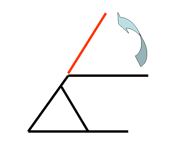
Provided the model is a correct comm antenna the actual question is, can we pivot the radiating element so as to match the fin, like in red in the following diagram
[img]cid:part1.258513B1.2B89A41E(at)free.fr[/img]
Of course this would involve removing some rivets, but from an electrical point of view, would such a "sweep" be acceptable ?
Thank you,
--
Best regards,
Gilles
http://contrails.free.fr
http://lapierre.skunkworks.free.fr
|
I'm no antenna expert, but I'd bet that a base loaded whip (like a 'rubber ducky' off a handheld) would work about as well as  radically altering the tuning of the Archer antenna. Or maybe not. 
 Virus-free. www.avast.com [url=#DAB4FAD8-2DD7-40BB-A1B8-4E2AA1F9FDF2][/url] Virus-free. www.avast.com [url=#DAB4FAD8-2DD7-40BB-A1B8-4E2AA1F9FDF2][/url]
| | - The Matronics AeroElectric-List Email Forum - | | | Use the List Feature Navigator to browse the many List utilities available such as the Email Subscriptions page, Archive Search & Download, 7-Day Browse, Chat, FAQ, Photoshare, and much more:
http://www.matronics.com/Navigator?AeroElectric-List |
|
| Description: |
|
| Filesize: |
3.94 KB |
| Viewed: |
3515 Time(s) |
|
|
|
| Back to top |
|
 |
kuffel(at)cyberport.net
Guest
|
 Posted: Sat Dec 08, 2018 8:48 pm Post subject: Bob Archer comm antenna dimensions ? Posted: Sat Dec 08, 2018 8:48 pm Post subject: Bob Archer comm antenna dimensions ? |
 |
|
Gilles,


 I used to be an antenna expert.


 The Archer antenna should work better with the  radiating element unbent.  In fact, it would work best with the radiating  element at 90 degrees to the base.  But you might have a bigger  issue.  This antenna requires a mass of metal, like a wing,  electrically connected along the base to serve as a ground plane.  Does the  aircraft have a metal fuselage or stabilizer.


 Another issue is the rudder tube, if metal.   If the distance from the front of the rudder to the antenna radiator is too  short, say around a foot or two, you will have a null in your reception toward  the rear.  The problem is even worse if the rudder is also  metal.


 A possible solution might be a bent 1/2 wave  dipole.  The 1/4 wave part fed by the coax center wire would fit up  the fin from the base, essentially the same as the radiating element on the  Archer.  The other half of the dipole would be attached forward to the  underside of the fuselage top.  The shield of the coax would be attached to  this other half.  Sort of an L in profile from the right side with the  coax cable attached at the bend.  I would use copper sheet 1/2 - 3/4 inch  wide for the elements.


 If this simple antenna is not possible for some  reason then more complex arrangements start appearing such as dual end coil  loaded dipoles.  This could be made to fit in the fin but then you are  getting into the area of much tinkering and antenna analyzers, etc.


 Tom Kuffel

 Virus-free. www.avast.com [url=#DAB4FAD8-2DD7-40BB-A1B8-4E2AA1F9FDF2] [/url] Virus-free. www.avast.com [url=#DAB4FAD8-2DD7-40BB-A1B8-4E2AA1F9FDF2] [/url]
| | - The Matronics AeroElectric-List Email Forum - | | | Use the List Feature Navigator to browse the many List utilities available such as the Email Subscriptions page, Archive Search & Download, 7-Day Browse, Chat, FAQ, Photoshare, and much more:
http://www.matronics.com/Navigator?AeroElectric-List |
|
|
|
| Back to top |
|
 |
kuffel(at)cyberport.net
Guest
|
|
| Back to top |
|
 |
gilles.thesee(at)free.fr
Guest
|
 Posted: Sun Dec 09, 2018 4:30 am Post subject: Bob Archer comm antenna dimensions ? Posted: Sun Dec 09, 2018 4:30 am Post subject: Bob Archer comm antenna dimensions ? |
 |
|
Le 09/12/2018 à 06:26, The Kuffels a écrit :
| Quote: | Â
What model Archer antenna does your friend have. Archer offers a compressed dipole (looks like a weird "3") model SA006 which is 26.5" tall by 12" wide.
Â
|
Hi all,
Thank you to all who answered.
My friend's model is the SA001A. He just mentionned the SA006 which could have been used, but he has already received the SA001A.
Here are some info about the present project :
It is a very small airplane, in the 100hp/140kt cruise category.
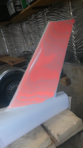
The fuselage is carbon fiber, with the fin, rudder post and rudder intentionally made of glass fiber (shown in red below) :
[img]cid:part1.FEECB98A.94C8A71D(at)free.fr[/img]
We will try to "unbend" the radiating element to have it more perpendicular to the base/ground element and fit in the tail fin, and as advised I'll borrow a SWR-meter to verify this does not harm the antenna efficiency.
Our intention is to use the same principle as in our first project to connect the antenna ground element to the carbon fuselage.
Concerning this first project, still flying - and transmitting - great after 15 years.
At the time Bob Archer kindly answered our many questions, and here is how we installed the antenna with great success :
The antenna is located in the right wingtip, intentionally made of glass instead of carbon as the rest of the airplane :

Mr Archer told us that would could "unbend" the radiating element to match the wingtip shape.
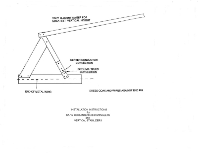
He also gave his advice on how to connect the ground element to the wing carbon skin :

Thank you for your help,
--
Best regards,
Gilles
http://contrails.free.fr
http://lapierre.skunkworks.free.fr
| | - The Matronics AeroElectric-List Email Forum - | | | Use the List Feature Navigator to browse the many List utilities available such as the Email Subscriptions page, Archive Search & Download, 7-Day Browse, Chat, FAQ, Photoshare, and much more:
http://www.matronics.com/Navigator?AeroElectric-List |
|
| Description: |
|
| Filesize: |
78.71 KB |
| Viewed: |
3503 Time(s) |
|
|
|
| Back to top |
|
 |
nuckolls.bob(at)aeroelect
Guest
|
 Posted: Sun Dec 09, 2018 7:25 am Post subject: Bob Archer comm antenna dimensions ? Posted: Sun Dec 09, 2018 7:25 am Post subject: Bob Archer comm antenna dimensions ? |
 |
|
At 11:46 AM 12/8/2018, you wrote:
| Quote: | Hi all,
Some 15 years ago we ordered a Bob Archer comm antenna for installation in our wingtip, and have been very satisfied with it.
Here is a sketch of our 15 year old antenna :
[img]cid:.0[/img]
A buddy of mine launches into another project and just received a new Archer antenna to install in his tail fin, but the dimensions and shape seem different, and the rivets prevent the upper segment from being swept up to fit into the tail.
Although the antenna is labelled "Comm", we are finally not sure the model is a VHF one.
Does any of you gentlemen have any information as to the shape and dimensions of the present time Archer comm antennas - or VOR antennas - so we could clarify the matter ?
|
Antennas come in a constellation of shapes
and sizes tailored FIRST to be efficient
at the transmission/reception of radio
energy. The antenna you've cited was
originally a VOR antenna designed to mount
under the wing tip of an RV.
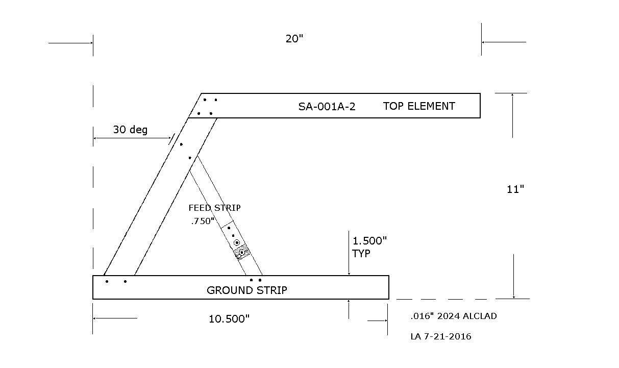
The short, horizontal section riveted to the close-out
rib of the wing. It's essentially a bent,
1/4 wave radiator with a 'gamma match'.
Further, due to it's operational orientation
wtih the earth, it's fundamentally a horizontally
polarized antenna.
https://tinyurl.com/ycxlsd4d
Later in Bob's OBAM aviation efforts, he
offered a slightly smaller (Comm frequencies)
version (1A)
https://tinyurl.com/y9xenkj6
but it too was intended for use on METAL aricraft
with non-metallic fin/tip caps. When this
antenna is installed on the wing, it's deficiencies
as a horizontally polarized antenna are partially
offset by attaching the base in the lowest practical
orientation on the rib and deflecting the
radiating element upward until flush with the
upper, inside surface of the wing tip fairing.
Many builders have reported good results with
this compromised configuration as a COMM antenna.
Nonetheless, this antenna is not suitable
for use on a totally composite aircraft
as it depends on metallic structure for
a ground plane.
Bob . . .
| | - The Matronics AeroElectric-List Email Forum - | | | Use the List Feature Navigator to browse the many List utilities available such as the Email Subscriptions page, Archive Search & Download, 7-Day Browse, Chat, FAQ, Photoshare, and much more:
http://www.matronics.com/Navigator?AeroElectric-List |
|
| Description: |
|
| Filesize: |
25.6 KB |
| Viewed: |
3496 Time(s) |
|
|
|
| Back to top |
|
 |
gilles.thesee(at)free.fr
Guest
|
 Posted: Mon Dec 10, 2018 4:20 am Post subject: Bob Archer comm antenna dimensions ? Posted: Mon Dec 10, 2018 4:20 am Post subject: Bob Archer comm antenna dimensions ? |
 |
|
Le 09/12/2018 à 16:24, Robert L. Nuckolls, III a écrit :
| Quote: |
Nonetheless, this antenna is not suitable
for use on a totally composite aircraft
as it depends on metallic structure for
a ground plane. |
Bob,
Thank you for taking the time to answer.
As mentioned in a previous message, we have had great success with Bob Archer's wingtip antenna, possibly due to the carbon fiber wing playing the role of the metallic structure ?
We took special care to ensure good electrical contact between the antenna ground element and the carbon wing skin.
Also our wingtip curves up to vertical, so the radiating element is nearly vertical, which may have helped.
Our VHF range is currently 100/150 nautical miles (at) 2000 ft QNH, and of course much more (though useless) at higher altitudes.
--
Best regards,
Gilles
http://contrails.free.fr
http://lapierre.skunkworks.free.fr
| | - The Matronics AeroElectric-List Email Forum - | | | Use the List Feature Navigator to browse the many List utilities available such as the Email Subscriptions page, Archive Search & Download, 7-Day Browse, Chat, FAQ, Photoshare, and much more:
http://www.matronics.com/Navigator?AeroElectric-List |
|
|
|
| Back to top |
|
 |
|
|
You cannot post new topics in this forum
You cannot reply to topics in this forum
You cannot edit your posts in this forum
You cannot delete your posts in this forum
You cannot vote in polls in this forum
You cannot attach files in this forum
You can download files in this forum
|
Powered by phpBB © 2001, 2005 phpBB Group
|


