 |
Matronics Email Lists
Web Forum Interface to the Matronics Email Lists
|
| View previous topic :: View next topic |
| Author |
Message |
nuckolls.bob(at)aeroelect
Guest
|
 Posted: Thu Apr 16, 2020 4:48 am Post subject: Z-12 Architecture, Back-Up Alternator Wiring Posted: Thu Apr 16, 2020 4:48 am Post subject: Z-12 Architecture, Back-Up Alternator Wiring |
 |
|
At 10:47 PM 4/15/2020, you wrote:
| Quote: | --> AeroElectric-List message posted by: "MFleming" <sagriver(at)icloud.com>
Thank you for the feedback...
I found the files, can't wait to look them over thoroughly.
I'm planning on one Pmag...I'm not sure if that qualifies as electrically dependent but I would guess yes.
Is the new thinking that Z-12 is outdated? I worked my way through the book and really like Z-12. |
Z12 works . . . it's flying on a boat-load
of TC SE aircraft. The only thing I would
change is to replace the SB-1 regulator
with a generic "ford" regulator. The
AUX ALTernator runs for seconds during pre-flight
and otherwise only when needed . . . which
will be rare.
LV warning and OV protection in the full-up
SB-1 controller adds no remarkable value.
The rudimentary regulator will be just
fine running 'barefoot' for what should
not exceed a few hours in the lifetime
of the airplane.
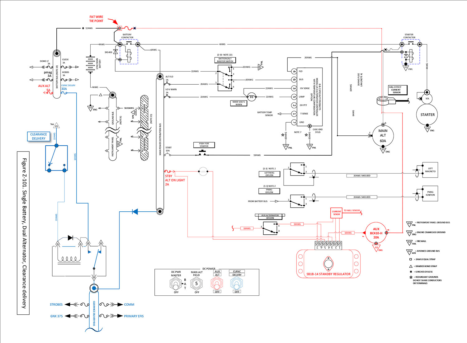
Figure Z101 depicts this recommendation
as an alternative to Z12 which also
offers the 3-layer functionality of
Z13/8 and the previously offered
Z13/20. But Z12 as published is
just fine if that's your wish.
Bob . . .
| | - The Matronics AeroElectric-List Email Forum - | | | Use the List Feature Navigator to browse the many List utilities available such as the Email Subscriptions page, Archive Search & Download, 7-Day Browse, Chat, FAQ, Photoshare, and much more:
http://www.matronics.com/Navigator?AeroElectric-List |
|
|
|
| Back to top |
|
 |
MFleming

Joined: 31 Oct 2017
Posts: 17
|
| Posted: Tue Apr 28, 2020 8:08 pm Post subject: Re: Z-12 Architecture, Back-Up Alternator Wiring |
|
|
After looking over Z101, this is my first try at an architecture that would fit my mission.


Criticism will be taken as constructive, no offense taken.


Looking into my avionics suite, the Garmin GAD 27 controller should prevent brown outs so I eliminated the BO option.


The idea of having a clearance delivery bus to upload flight plans and well, get a clearance, really appealed to me so it's included. The strobes are on that bus so I would not walk away from the aircraft with the clearance delivery bus still energized.


Speaking to B&C today about their standby alternator had me include their standby regulator. The wiring of it is per their drawings. B&C say’s the standby alternator wired this way would run in parallel with the main alternator and would be excited and pick up the load when the main bus voltage fell below a predefined level and would need no pilot input. I’m not sure why they show a switch but I included it.


My plans are to have one Pmag or a SureFly mag replacement and a traditional mag, so that setup is included.


I’m sure I missed something and am looking forward to learning even more than I already have.
| | - The Matronics AeroElectric-List Email Forum - | | | Use the List Feature Navigator to browse the many List utilities available such as the Email Subscriptions page, Archive Search & Download, 7-Day Browse, Chat, FAQ, Photoshare, and much more:
http://www.matronics.com/Navigator?AeroElectric-List |
|
| Description: |
|
| Filesize: |
215.76 KB |
| Viewed: |
8370 Time(s) |
|
_________________
Michael Fleming |
|
| Back to top |
|
|
nuckolls.bob(at)aeroelect
Guest
|
| Posted: Wed Apr 29, 2020 7:30 pm Post subject: Z-12 Architecture, Back-Up Alternator Wiring |
|
|
| Quote: | | Speaking to B&C today about their standby alternator had me include their standby regulator. The wiring of it is per their drawings. B&C say’s the standby alternator wired this way would run in parallel with the main alternator and would be excited and pick up the load when the main bus voltage fell below a predefined level and would need no pilot input. I’m not sure why they show a switch but I included it. |
Yup, that's what it was designed to do. If $cash$ is
no object, the system will certainly perform as
advertised. I designed it.
I suggest that all that automation has no direct
benefit with respect to 'saving the day' in the
event of main alternator failure. The majority
of such systems will never be called upon to
perform their intended task. Well maintained
alternator up front is going to run TBO on
the engine. The Z101 philosophy was, "yeah,
I want that capability there and available with
just the flip of a switch for the least
cost of installation." But it's your choice.
| Quote: | | My plans are to have one Pmag or a SureFly mag replacement and a traditional mag, so that setup is included. |
What's your proposed fuel delivery system?
| Quote: | | I’m sure I missed something and am looking forward to learning even more than I already have. |
If your engine isn't electrically dependent
and you want the aux alternator will full
compliment of bells/whistles, then Z12
is your best fit.
Clearance delivery option comes standard on the E-bus
Bob . . .
| | - The Matronics AeroElectric-List Email Forum - | | | Use the List Feature Navigator to browse the many List utilities available such as the Email Subscriptions page, Archive Search & Download, 7-Day Browse, Chat, FAQ, Photoshare, and much more:
http://www.matronics.com/Navigator?AeroElectric-List |
|
|
|
| Back to top |
|
|
MFleming
Joined: 31 Oct 2017
Posts: 17
|
| Posted: Fri May 01, 2020 2:12 pm Post subject: Re: Z-12 Architecture, Back-Up Alternator Wiring |
|
|
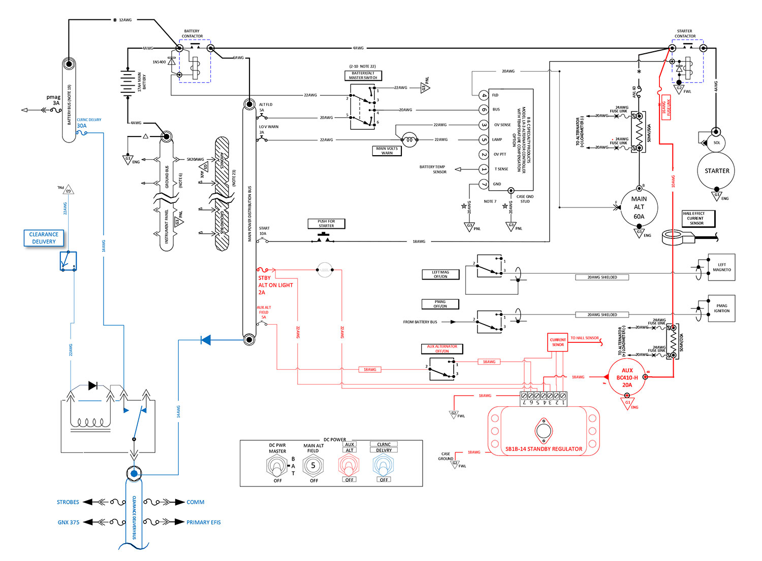
So I took your advice and crafted a Z-12 version.


Can some light be shed on the use of shunts as well as a Hall effect sensor?

I would like to have the information to my EFIS from each alternator. Do I have this drawn correctly?


Also, I was questioned on VAF about the Instrument panel ground bus and Avionics ground bus being tied together with the five 2AWG wires. It was also suggested they could be the same bus. I didn't have a ready answer.


EDIT: My fuel delivery will be a standard booster pump and fuel injection.
| | - The Matronics AeroElectric-List Email Forum - | | | Use the List Feature Navigator to browse the many List utilities available such as the Email Subscriptions page, Archive Search & Download, 7-Day Browse, Chat, FAQ, Photoshare, and much more:
http://www.matronics.com/Navigator?AeroElectric-List |
|
| Description: |
|
| Filesize: |
212.6 KB |
| Viewed: |
8307 Time(s) |
|
_________________
Michael Fleming |
|
| Back to top |
|
|
jonlaury
Joined: 06 Nov 2006
Posts: 336
|
| Posted: Sat May 02, 2020 8:26 am Post subject: Re: Z-12 Architecture, Back-Up Alternator Wiring |
|
|
It may be my brain that is missing the connection, but I don't see the electrical path that feeds bus power to the LR3. The pole called upon to switch bus power goes nowhere.

Shouldn't the arc path of pole 5  be connected to terminal 4, replicating pole 2 and terminals 1 & 3?
| | - The Matronics AeroElectric-List Email Forum - | | | Use the List Feature Navigator to browse the many List utilities available such as the Email Subscriptions page, Archive Search & Download, 7-Day Browse, Chat, FAQ, Photoshare, and much more:
http://www.matronics.com/Navigator?AeroElectric-List |
|
|
|
| Back to top |
|
|
nuckolls.bob(at)aeroelect
Guest
|
| Posted: Sat May 02, 2020 8:35 am Post subject: Z-12 Architecture, Back-Up Alternator Wiring |
|
|
At 05:12 PM 5/1/2020, you wrote:
| Quote: | --> AeroElectric-List message posted by: "MFleming" <sagriver(at)icloud.com>
So I took your advice and crafted a Z-12 version. |
okay. dump the shunts. run BOTH b-leads trough
the one hall effect sensor.
| Quote: | | Can some light be shed on the use of shunts as well as a Hall effect sensor? |
don't need both
| Quote: | I would like to have the information to my EFIS from each alternator. Do I have this drawn correctly?
Also, I was questioned on VAF about the Instrument panel ground bus and Avionics ground bus being tied together with the five 2AWG wires. It was also suggested they could be the same bus. I didn't have a ready answer. |
the 'panel' ground bus is normally on the cabin
side of the firewall. I think I'm going to
change the name to 'cabin ground bus'. The avionics
ground is on the panel, centrally located to electro-
whizzies that reside on the panel.
Don't need a fuse block for the 'battery bus'. Put
the clearance delivery relay right close to the
battery contactor. Use a 3a inline fuse to feed
the pmag.
Getting ready to launch for Enid . . . we
live 100 miles from everywhere . . . got some
shopping to do.
We'll be back tonight.
Bob . . .
| | - The Matronics AeroElectric-List Email Forum - | | | Use the List Feature Navigator to browse the many List utilities available such as the Email Subscriptions page, Archive Search & Download, 7-Day Browse, Chat, FAQ, Photoshare, and much more:
http://www.matronics.com/Navigator?AeroElectric-List |
|
|
|
| Back to top |
|
|
foghorn757(at)gmail.com
Guest
|
| Posted: Sat May 02, 2020 1:44 pm Post subject: Z-12 Architecture, Back-Up Alternator Wiring |
|
|
I’d suggest not posting your electrical ideas on VAF. You’ll get 100 different opinions. Here most folks are on the same sheet of music. These Z figures work and can be modified to meet your goals.
Jeff Parker
Sent from my iPad
| Quote: | On May 2, 2020, at 12:40, Robert L. Nuckolls, III <nuckolls.bob(at)aeroelectric.com> wrote:
At 05:12 PM 5/1/2020, you wrote:
| Quote: | --> AeroElectric-List message posted by: "MFleming" <sagriver(at)icloud.com>
So I took your advice and crafted a Z-12 version. |
okay. dump the shunts. run BOTH b-leads trough
the one hall effect sensor.
| Quote: | | Can some light be shed on the use of shunts as well as a Hall effect sensor? |
don't need both
| Quote: | I would like to have the information to my EFIS from each alternator. Do I have this drawn correctly?
Also, I was questioned on VAF about the Instrument panel ground bus and Avionics ground bus being tied together with the five 2AWG wires. It was also suggested they could be the same bus. I didn't have a ready answer. |
the 'panel' ground bus is normally on the cabin
side of the firewall. I think I'm going to
change the name to 'cabin ground bus'. The avionics
ground is on the panel, centrally located to electro-
whizzies that reside on the panel.
Don't need a fuse block for the 'battery bus'. Put
the clearance delivery relay right close to the
battery contactor. Use a 3a inline fuse to feed
the pmag.
Getting ready to launch for Enid . . . we
live 100 miles from everywhere . . . got some
shopping to do.
We'll be back tonight.
Bob . . .
|
| | - The Matronics AeroElectric-List Email Forum - | | | Use the List Feature Navigator to browse the many List utilities available such as the Email Subscriptions page, Archive Search & Download, 7-Day Browse, Chat, FAQ, Photoshare, and much more:
http://www.matronics.com/Navigator?AeroElectric-List |
|
|
|
| Back to top |
|
|
johnbright
Joined: 14 Dec 2011
Posts: 165
Location: Newport News, VA
|
| Posted: Sat May 02, 2020 4:41 pm Post subject: Re: Z-12 Architecture, Back-Up Alternator Wiring |
|
|
| jonlaury wrote: | | ... I don't see the electrical path that feeds bus power to the LR3. The pole called upon to switch bus power goes nowhere... |
That's a progressive three-position switch, off, battery contactor on, battery contactor and main alternator on.
Ref the paragraph heading "Switches" in Chapter 1, and notes 15 and 22 in Appendix Z of Aeroelectric Connection book.
| | - The Matronics AeroElectric-List Email Forum - | | | Use the List Feature Navigator to browse the many List utilities available such as the Email Subscriptions page, Archive Search & Download, 7-Day Browse, Chat, FAQ, Photoshare, and much more:
http://www.matronics.com/Navigator?AeroElectric-List |
|
_________________
John Bright, RV-6A, at FWF, O-360
Z-101 single batt dual alt SDS EM-5-F.
john_s_bright@yahoo.com, Newport News, Va
N1921R links |
|
| Back to top |
|
|
nuckolls.bob(at)aeroelect
Guest
|
| Posted: Sun May 03, 2020 5:12 pm Post subject: Z-12 Architecture, Back-Up Alternator Wiring |
|
|
At 05:12 PM 5/1/2020, you wrote:
| Quote: | --> AeroElectric-List message posted by: "MFleming" <sagriver(at)icloud.com>
So I took your advice and crafted a Z-12 version.
|
<SNIP>
| Quote: | --------
Michael Fleming
|
Michael,
Did about 200 miles of 'asphalt engineering'
yesterday on this thread. Picked up some parts
for a friend's welder/generator in Enid. His
Chute is electro-hydraulic and he had some
cattle to work today
I've incorporated some of your input along with
musings from the List and my own starry-eyed
stare down the highway.
https://tinyurl.com/y9n57vlw
This drawing needs some notes to explain
on some new ideas:
Z12 lite could be pretty simple. No optional
busses. Dual alternator dependability combined
with a dutifully maintained battery would
take you far and in confidence. This drawing
illustrates and preserves the aux alternator
installation as offered by B&C.
Depending on proposed accessories and operating
modes one might wish to add battery or
clearance delivery/endurance busses. Purely
optional . . . if you gotta use for one,
add it.
Question: your drawing shows a fused feeder off
the battery to the p-mag. What is the rational
for utilizing this source as opposed to simply
tying it to the main bus? What is the
current draw of this feature on the p-mag?
Bob . . .
| | - The Matronics AeroElectric-List Email Forum - | | | Use the List Feature Navigator to browse the many List utilities available such as the Email Subscriptions page, Archive Search & Download, 7-Day Browse, Chat, FAQ, Photoshare, and much more:
http://www.matronics.com/Navigator?AeroElectric-List |
|
|
|
| Back to top |
|
|
MFleming
Joined: 31 Oct 2017
Posts: 17
|
| Posted: Mon May 04, 2020 12:54 pm Post subject: Re: Z-12 Architecture, Back-Up Alternator Wiring |
|
|
Bob,


Well I though we were isolated living in Alaska back in the day but southern Kansas looks pretty  far from welder parts ;- )

I was visiting Oklahoma City, Bartlesville, Fort Smith and Independence last fall...lots of driving.


Thank you for spending time thinking about this little venture of mine. Unfortunately the link takes me to the AeroElectric Connection page but no file. Looked in the .pdf folder but no luck.


Not sure of the Pmag current draw but the manual says to use a 3amp pull-able breaker. To be honest, the depiction of the fused feeder was just copied from Z-12. I was thinking if things really went bad with the contacter open and a mag dead the Pmag would still be operating.


Looking forward to seeing the drawing.

-M
| | - The Matronics AeroElectric-List Email Forum - | | | Use the List Feature Navigator to browse the many List utilities available such as the Email Subscriptions page, Archive Search & Download, 7-Day Browse, Chat, FAQ, Photoshare, and much more:
http://www.matronics.com/Navigator?AeroElectric-List |
|
_________________
Michael Fleming |
|
| Back to top |
|
|
nuckolls.bob(at)aeroelect
Guest
|
| Posted: Mon May 04, 2020 4:00 pm Post subject: Z-12 Architecture, Back-Up Alternator Wiring |
|
|
At 03:54 PM 5/4/2020, you wrote:
| Quote: | --> AeroElectric-List message posted by: "MFleming" <sagriver(at)icloud.com>
Bob,
Well I though we were isolated living in Alaska back
in the day but southern Kansas looks pretty far from
welder parts ;- ) |
Actually, his problem was with compatibility
of an extension cord that was going to run
from his Welder/GenSet to the pump on the
chute. Needed a somewhat rare 50A-4Wire
plug. But even the smallest necessity can
hold up a expensive operation! On
several occasions I've made trips to metropolitan
supply sources for relatively trivial items
that would hold a $1000/day cattle operation hostage!
| Quote: | Thank you for spending time thinking about this little venture of mine.
Unfortunately the link takes me to the AeroElectric Connection page but
no file. Looked in the .pdf folder but no luck. |
Sorry 'bout that. I had posted the wrong file so
even if the link was good, the resulting
download was not. Here's a better shot at
it.
https://tinyurl.com/ydbc5xqt
| Quote: | Not sure of the Pmag current draw but the manual says to use a 3amp pull-able
breaker. To be honest, the depiction of the fused feeder was just copied
from Z-12. I was thinking if things really went bad with the contacter
open and a mag dead the Pmag would still be operating. |
We're talking about a P-Mag, not an E-Mag . . . right?
P-mags have built in alternators. As I recall, the battery
assist was to support cranking and hand-propping
the airplane.
Haven't talked with those guys in a long time. I'll
call down there tomorrow and get my knowledge nugget
updated.
Bob . . .
| | - The Matronics AeroElectric-List Email Forum - | | | Use the List Feature Navigator to browse the many List utilities available such as the Email Subscriptions page, Archive Search & Download, 7-Day Browse, Chat, FAQ, Photoshare, and much more:
http://www.matronics.com/Navigator?AeroElectric-List |
|
|
|
| Back to top |
|
|
|
|
You cannot post new topics in this forum
You cannot reply to topics in this forum
You cannot edit your posts in this forum
You cannot delete your posts in this forum
You cannot vote in polls in this forum
You cannot attach files in this forum
You can download files in this forum
|
Powered by phpBB © 2001, 2005 phpBB Group
|

