 |
Matronics Email Lists
Web Forum Interface to the Matronics Email Lists
|
| View previous topic :: View next topic |
| Author |
Message |
nuckolls.bob(at)aeroelect
Guest
|
 Posted: Wed Jun 03, 2020 7:34 am Post subject: Looking for help finalysing my Cozy's electrical system Posted: Wed Jun 03, 2020 7:34 am Post subject: Looking for help finalysing my Cozy's electrical system |
 |
|
At 11:39 PM 5/31/2020, you wrote:
| Quote: | --> AeroElectric-List message posted by: "johnbright" <john_s_bright(at)yahoo.com>
Single points of failure:
All four injectors are powered by one reley, wire, and fuse link.
Both pumps are powered thru the same switch. |
Agreed. Will the engine run if one injector
becomes inop? Suggest separate switches for
each fuel pump. Ditch the 'auto' feature'
| Quote: | Questions:
The injectors have fuse links in the harness. Are they sized so they won't pop the one fuse link that feeds all four injectors?
What happens if both injector enable inputs are un-grounded?
Why are there relays for removing power from the coils? |
Strive to reduce relays to minimum. I recall
seeing this installation published somewhere.
http://aeroelectric.com/Pictures/Misc/Too_Many_Relays.jpg
. . . mind boggling.
| Quote: | What is the EFII Syst 32 Inj Pwr Module? I would have thought each ECU box has open collector injector drivers inside.
Will the automatic aux pump feature result in a relaxation oscillator? (No pressure, pump on... now we have pressure, pump off, repeat.)
Where are the batteries located?
Thoughts/IMO:
It would be simpler to have separate toggle switches for left and right coil "P-Leads". |
Agreed
| Quote: | | It wouild be simpler to have an SPDT switch for injector enable grounds like EFII illustrates but what is the effect if the ground is lost to both injector enables? |
Something to sort out . . . potential
single point of failure.
| Quote: | | I don't know how to have faith in Bus Manager (I know you mentioned you are not using Bus Manager) or EFII in general when they show un-necessary SPOFs that will stop the engine. Ref EFII Dwg 9 rev 5/19 that you attached. |
How about a Z101 engine bus? It's already
managed.
| Quote: | 50A is more than an engine bus requires. I am planning on dual four cylinder SDS EFI+I on O-360 and my calculations show:
ECU 0.13A |
Agreed
| Quote: | Coilpack 1.1A at cruise
Fuel pump 5.25A at 45 PSI (Walbro GSL393)
14.5 Ohm injectors 0.32A each at cruise (32% duty cycle, 10 GPH)
I plan to put both EFI+I systems (pri and bak) on one engine bus and the current draw is less than 20A (15A with both pumps and coils running for low altitude; 8.2A with one coil and one pump running in current conservation mode).
I'm planning on an adaptation of Z-101 which is simpler than Z-14 and IMO just as reliable.
It would be simpler and more reliable to have separate toggle switches for the main and aux fuel pumps and eliminate the fuel pressure switch.
The fuel pressure switch is called NO; I would think that means it is open when there is no fuel pressure so the logic is backwards.
You mentioned dwg 1.04 but attached 1.00. |
Wire and fusing sizes depicted are
not clear as to design goals. Diode
-ored power sources should locate
diodes at the load end of each feed.
As shown, faults downstream of diodes
would take out both feeders. Fusible
links are not useful here . . . in fact,
any fault that would open a fusible link
would take out both fuses.
The drawing is exceedingly 'busy'. A three
source, dual feed engine bus can replace
un-necessary 'redundancy' . . . offers opportunity
for each load to enjoy its own protected
feeder thus maximizing failure tolerance
while reducing system costs, weight and parts
count.
Bob . . .
| | - The Matronics AeroElectric-List Email Forum - | | | Use the List Feature Navigator to browse the many List utilities available such as the Email Subscriptions page, Archive Search & Download, 7-Day Browse, Chat, FAQ, Photoshare, and much more:
http://www.matronics.com/Navigator?AeroElectric-List |
|
|
|
| Back to top |
|
 |
Zoom2136
Joined: 03 Oct 2018
Posts: 7
Location: Montreal
|
 Posted: Thu Jun 04, 2020 7:05 pm Post subject: Re: Looking for help finalysing my Cozy's electrical syste Posted: Thu Jun 04, 2020 7:05 pm Post subject: Re: Looking for help finalysing my Cozy's electrical syste |
 |
|
Hi Mr Nuckolls,
Thank you for taking the time to comment on my electrical system, it's much appreciated. I've taken notes of your comments and have a few questions. I've made some changes to my diagrams that go against some of your recommendations, but please know that they are more to illustrate my ideas than a design decision on my part.
Again, I really appreciate you and Jonhbright's taking time to help me with this project.
| nuckolls.bob(at)aeroelect wrote: |
Will the engine run if one injector becomes inop? Suggest separate switches for each fuel pump. Ditch the 'auto' feature' |
Yes, the engine will run rough with one injector not firing, but it will run rough. This would require to land ASAP though...
OK for the switches, but this is a Cozy with everything in the back, would it be better to have short runs of higher amp wires kept to a minimum and switch EB1 & EB2 with relays? Same logic would apply to the MAIN & AUX FUEL PUMP that could be powered through dedicated relays? Would having dedicated relays (4) mitigate the risk of using relays instead of 4 SPST switches that carry all the current?
| Quote: | Questions:
Strive to reduce relays to minimum. |
Agreed, but what about what I've noted above? In my mind I could run a pair of 22 AWG wires with inline 5A fuses from each battery from the FW to SPST switches at the IP and back to 2 relays powering EB1 & EB2 located on the cabin side of the FW. Or should a just run a pair of 10 AWG wires from the FW to switches at the IP and back to the FW, a +/- 25 feet run? The same logic would apply to the fuel pumps except that the relays coil would be power from either EB1 & EB2... Would that make for a bit less weight and more durable switches (less AMPs)?
| Quote: | What is the EFII Syst 32 Inj Pwr Module? I would have thought each ECU box has open collector injector drivers inside.
Will the automatic aux pump feature result in a relaxation oscillator? (No pressure, pump on... now we have pressure, pump off, repeat.)
Where are the batteries located?
Thoughts/IMO:
It would be simpler to have separate toggle switches for left and right coil "P-Leads".
Agreed |
In a Cozy (same as a Long EZ) everthing is in the back, including the batteries which normally sit above the main wing spar at the FW.
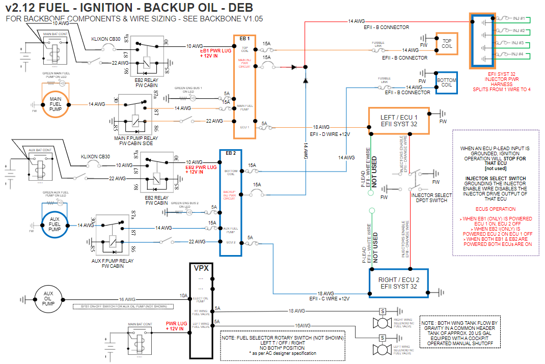
P-Leads grounds have been omitted in v2.12 as the ECU are powered directly from either EB1 or EB2 and they are turned off by killing either engine bus. No need to ground them to stop their operation.
EFII PWR MODULE is a misnomer, it is a 1:4 wire part of a larger harness. There is no fuse link is the single wire (my mistake), only in the smaller 4 wires before each injector. So it is 15 amp breaker --- harness 1:4 wire --- fuse link just before each injector.
EFFI does control directly the injector cycle via a harness, but power is supplied to each injector via another 1:4 power wire mentionned before.
| Quote: | It wouild be simpler to have an SPDT switch for injector enable grounds like EFII illustrates but what is the effect if the ground is lost to both injector enables?
Something to sort out . . . potential
single point of failure. |
Yes, and because it is a long run from the ECU to the IP and back to the FW ground block, I'm thinking of using a DPDT switch with 2 ground wires. So 2 complete ground paths for these critical injector select ground wires. I beleive this takes care of one SPOF unless the DPDT switch is a problem...
| Quote: | I don't know how to have faith in Bus Manager (I know you mentioned you are not using Bus Manager) or EFII in general when they show un-necessary SPOFs that will stop the engine. Ref EFII Dwg 9 rev 5/19 that you attached.
How about a Z101 engine bus? It's already
managed. |
I know we should not get fixated on an architecture, but I now have a good understanding of Z14 and find it fits my needs. My original design had a dual feed bus, but I prefer to have 2 independent engine bus that I can shut off 1 at a time to kill a complete subsystem (ECU, COIL & 1 FUEL PUMP) quickly with only having to make sure that the proper FUEL PUMP is ON prior to flipping a single switch.
| Quote: | 50A is more than an engine bus requires. I am planning on dual four cylinder SDS EFI+I on O-360 and my calculations show:
ECU 0.13A
Agreed |
Yes, this is why I changed them to 30A breakers. Would a pair of 35A ANL be better since the engine buses are directly tied to the batteries?
| Quote: | Coilpack 1.1A at cruise
Fuel pump 5.25A at 45 PSI (Walbro GSL393)
14.5 Ohm injectors 0.32A each at cruise (32% duty cycle, 10 GPH)
I plan to put both EFI+I systems (pri and bak) on one engine bus and the current draw is less than 20A (15A with both pumps and coils running for low altitude; 8.2A with one coil and one pump running in current conservation mode).
I'm planning on an adaptation of Z-101 which is simpler than Z-14 and IMO just as reliable.
It would be simpler and more reliable to have separate toggle switches for the main and aux fuel pumps and eliminate the fuel pressure switch.
The fuel pressure switch is called NO; I would think that means it is open when there is no fuel pressure so the logic is backwards.
You mentioned dwg 1.04 but attached 1.00.
Wire and fusing sizes depicted are not clear as to design goals. Diode-ored power sources should locate diodes at the load end of each feed. As shown, faults downstream of diodes would take out both feeders. Fusible links are not useful here . . . in fact, any fault that would open a fusible link would take out both fuses.
The drawing is exceedingly 'busy'. A three source, dual feed engine bus can replace un-necessary 'redundancy' . . . offers opportunity for each load to enjoy its own protected feeder thus maximizing failure tolerance while reducing system costs, weight and parts count. |
I've addressed your points (except changing the base architecture) in my latest version v2.12 and I used a few relays for the reason mentionned above. Wire sizing is going to be finalized in a later version, because I have thousands of feets of 18 AWG, so I've used it a lot in my diagrams even if it is oversized. As mentionned before, I've also used a few relays due the Cozy's unique layout (always open to change if relays are a definite no-no).
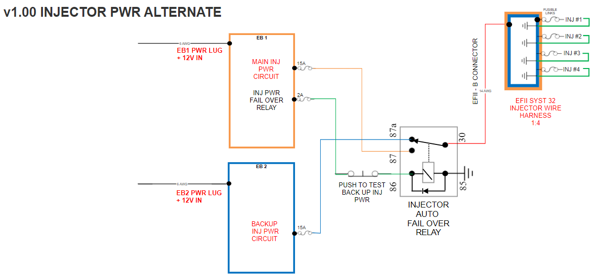
That being said, powering the injector is what I struggle the most with. In my v2.12 diagram, I've replaced the two 15A fuses with 15A breakers. Would having the ability to reset a breaker in flight enough to mitigate the risk of a "dual breaker pop" caused by a one of the fusable link in the injector feeds failing?
Alternatively, what I came up with is actually from an older design, it's "an automatic fail over circuit" using a changeover relay with a push to test button on its coil power path to be able to verify that both power paths are operational during preflight (see V1.00 Injector PWR Alternate). My reasoning (which may be flawed) is that this way, 1 of the two 15 amp breakers will always be isolated if a fusible link blows and try to pop/fry its upstream breaker. Now if this can cause a problem with the relay, like welding the contacts, that I don't know.
Would this mitigate this issue, or should I just leave the 2 diodes and two 15A breakers, include an emergency check list item (reset injector breakers once?), and be done with it.
| | - The Matronics AeroElectric-List Email Forum - | | | Use the List Feature Navigator to browse the many List utilities available such as the Email Subscriptions page, Archive Search & Download, 7-Day Browse, Chat, FAQ, Photoshare, and much more:
http://www.matronics.com/Navigator?AeroElectric-List |
|
| Description: |
|
| Filesize: |
43.91 KB |
| Viewed: |
4818 Time(s) |

|
| Description: |
|
| Filesize: |
136.9 KB |
| Viewed: |
4794 Time(s) |

|
| Description: |
|
| Filesize: |
107.28 KB |
| Viewed: |
4732 Time(s) |

|
_________________
Eric D
Cozy IIIx C-GEDZ |
|
| Back to top |
|
 |
johnbright

Joined: 14 Dec 2011
Posts: 165
Location: Newport News, VA
|
 Posted: Fri Jul 10, 2020 9:42 am Post subject: Re: Looking for help finalysing my Cozy's electrical syste Posted: Fri Jul 10, 2020 9:42 am Post subject: Re: Looking for help finalysing my Cozy's electrical syste |
 |
|
Hi Eric,


My thoughts:


The EFII harness has an un-necessary SPOF; powering all four injectors thru one wire. You do not have to accept this SPOF. I would assume the fusible links built into the harness are capable of opening the injector breakers. Power the four injectors thru four fuses, a 5A fuse is good for one injector.


Do the EFII supplied firewall connectors melt in a fire?


Does it make sense to have main reg v sense on VPX?


It's confusing to show injectors grounded within injector power harness.


The voltage regulator "bus" feed should have a 5A CB versus a fuse because of nuisnace trip potential of crowbar.


Replace circuit breakers with MIDIs or fuselink wire except voltage regulator "bus" feed needs to be a CB because of crowbar nuisance trips.


Design your electrical system for a simple, no questions asked, engine out procedure. You will forget details of your architechture and your intelligence will fall 90% when the engine quits.


Consider switching to Z-101.
| | - The Matronics AeroElectric-List Email Forum - | | | Use the List Feature Navigator to browse the many List utilities available such as the Email Subscriptions page, Archive Search & Download, 7-Day Browse, Chat, FAQ, Photoshare, and much more:
http://www.matronics.com/Navigator?AeroElectric-List |
|
_________________
John Bright, RV-6A, at FWF, O-360
Z-101 single batt dual alt SDS EM-5-F.
john_s_bright@yahoo.com, Newport News, Va
N1921R links |
|
| Back to top |
|
 |
Zoom2136
Joined: 03 Oct 2018
Posts: 7
Location: Montreal
|
 Posted: Sat Jul 11, 2020 6:09 pm Post subject: Re: Looking for help finalysing my Cozy's electrical syste Posted: Sat Jul 11, 2020 6:09 pm Post subject: Re: Looking for help finalysing my Cozy's electrical syste |
 |
|
Thanks John for taking the time to review my system.
| Quote: | | The EFII harness has an un-necessary SPOF; |
Yes, I'm thinking of splitting them up and running them through a dedicated connector.
| Quote: | | Do the EFII supplied firewall connectors melt in a fire? |
My harness and ECU shipped last week. I will have to check. If so, I can always repalce it with a MIL-SPEC connector.
| Quote: | | Does it make sense to have main reg v sense on VPX? |
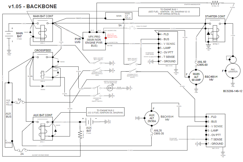
This is per the VPX doc. But, I see your point. I changed it to be powered by a 5A breaker & 20 AWG wire from the MAIN ALT BUS.
| Quote: | | It's confusing to show injectors grounded within injector power harness. |
Thanks, changed in my current version.
| Quote: | | The voltage regulator "bus" feed should have a 5A CB versus a fuse because of nuisnace trip potential of crowbar. |
Thanks, changed in me current version.
| Quote: | | Replace circuit breakers with MIDIs or fuselink wire except voltage regulator "bus" feed needs to be a CB because of crowbar nuisance trips. |
This will take some thinking, as I'm not familiar with MIDIs.
| Quote: | | Design your electrical system for a simple, no questions asked, engine out procedure. You will forget details of your architechture and your intelligence will fall 90% when the engine quits. |
Makes sense.
| Quote: | | Consider switching to Z-101. |
I'm now very familiar with Z-14, I'll check 101, but...
Thanks again.
| | - The Matronics AeroElectric-List Email Forum - | | | Use the List Feature Navigator to browse the many List utilities available such as the Email Subscriptions page, Archive Search & Download, 7-Day Browse, Chat, FAQ, Photoshare, and much more:
http://www.matronics.com/Navigator?AeroElectric-List |
|
_________________
Eric D
Cozy IIIx C-GEDZ |
|
| Back to top |
|
 |
|
|
You cannot post new topics in this forum
You cannot reply to topics in this forum
You cannot edit your posts in this forum
You cannot delete your posts in this forum
You cannot vote in polls in this forum
You cannot attach files in this forum
You can download files in this forum
|
Powered by phpBB © 2001, 2005 phpBB Group
|


