 |
Matronics Email Lists
Web Forum Interface to the Matronics Email Lists
|
| View previous topic :: View next topic |
| Author |
Message |
david(at)carter.net
Guest
|
 Posted: Wed Sep 30, 2020 1:27 pm Post subject: Z101 with Garmin GAD 27 voltage stabilizer Posted: Wed Sep 30, 2020 1:27 pm Post subject: Z101 with Garmin GAD 27 voltage stabilizer |
 |
|
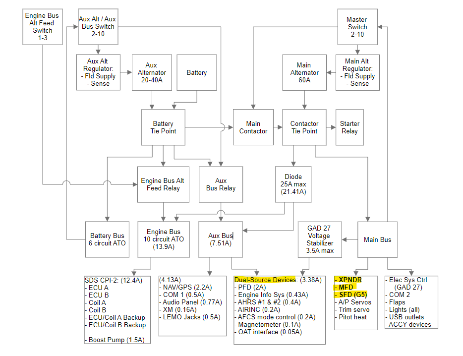
I have attached a power distribution block diagram (not a schematic) that I have been working on. I'm trying to puzzle through how best to take advantage of the voltage stabilizer built into the Garmin GAD 27.Â
The GAD 27 is Garmin's electrical system controller. It's a combo box that bundles several functions, including the voltage stabilizer, trim mixer, flap controller, wigwag control, panel light dimmer, etc. Â
I'm focused on how to best leverage the voltage stabilizer function to keep things running smoothly during engine start, and how to build in additional redundancy by using the dual diode-isolated power inputs available in many of the Garmin boxes by powering them both from the GAD 27 on the main bus, and from the Aux bus. I will admit that the failure modes in Z101 where this redundancy would be used should be exceedingly rare. But the dual power inputs are there, why not use them?
I have also highlighted 3 devices that have dual power inputs that I'm not planning to use. One of those, the G5 SFD, has it's own attached backup battery.
I appreciate any suggestions this group can provide.Â
[img]cid:ii_kfpwbpku0[/img]
---
David Carter
david(at)carter.net (david(at)carter.net)
| | - The Matronics AeroElectric-List Email Forum - | | | Use the List Feature Navigator to browse the many List utilities available such as the Email Subscriptions page, Archive Search & Download, 7-Day Browse, Chat, FAQ, Photoshare, and much more:
http://www.matronics.com/Navigator?AeroElectric-List |
|
| Description: |
|
| Filesize: |
78.7 KB |
| Viewed: |
1059 Time(s) |

|
|
|
| Back to top |
|
 |
jluckey(at)pacbell.net
Guest
|
| Posted: Wed Sep 30, 2020 2:49 pm Post subject: Z101 with Garmin GAD 27 voltage stabilizer |
|
|
David,

Wow! That's a lot of busses!  I count 4?  What airplane is this going in?  IIRC, you have an electrically-dependent engine, right?

The block diagram is not super useful for circuit analysis 'cuz it doesn't show how it's wired.  In other words, one could come up with lots of different way to implement what's shown on this Block diagram.  For meaningful analysis it would be easier to have a view that is "closer to the metal".

Do you have an actual schematic?  That might be more useful to the group to analyze.


-Jeff Luckey


                                                                    On Wednesday, September 30, 2020, 03:01:24 PM PDT, David Carter <david(at)carter.net> wrote:


                 I have attached a power distribution block diagram (not a schematic) that I have been working on. I'm trying to puzzle through how best to take advantage of the voltage stabilizer built into the Garmin GAD 27.


The GAD 27 is Garmin's electrical system controller. It's a combo box that bundles several functions, including the voltage stabilizer, trim mixer, flap controller, wigwag control, panel light dimmer, etc.

I'm focused on how to best leverage the voltage stabilizer function to keep things running smoothly during engine start, and how to build in additional redundancy by using the dual diode-isolated power inputs available in many of the Garmin boxes by powering them both from the GAD 27 on the main bus, and from the Aux bus. I will admit that the failure modes in Z101 where this redundancy would be used should be exceedingly rare. But the dual power inputs are there, why not use them?

I have also highlighted 3 devices that have dual power inputs that I'm not planning to use. One of those, the G5 SFD, has it's own attached backup battery.

I appreciate any suggestions this group can provide.

[img]cid:O0pdqxKYDNEvlkwuVkIC[/img]

---

David Carter

david(at)carter.net (david(at)carter.net)
| | - The Matronics AeroElectric-List Email Forum - | | | Use the List Feature Navigator to browse the many List utilities available such as the Email Subscriptions page, Archive Search & Download, 7-Day Browse, Chat, FAQ, Photoshare, and much more:
http://www.matronics.com/Navigator?AeroElectric-List |
|
| Description: |
|
| Filesize: |
78.7 KB |
| Viewed: |
1052 Time(s) |

|
|
|
| Back to top |
|
|
david(at)carter.net
Guest
|
| Posted: Wed Sep 30, 2020 3:01 pm Post subject: Z101 with Garmin GAD 27 voltage stabilizer |
|
|
This will be going into a retrofit of a flying RV-7A, equipped for IFR, with an electrically-dependent engine. Dual SDS CPI-2 ignition, but mechanical fuel injection & engine-driven fuel pump. I haven't developed the schematic yet, but it is almost 100% Z101. The only divergence is the GAD-27 & powering several devices off of two of the busses vs. just one. Maybe that's overkill.Â
---
David Carter
david(at)carter.net (david(at)carter.net)
On Wed, Sep 30, 2020 at 6:52 PM Jeff Luckey <jluckey(at)pacbell.net (jluckey(at)pacbell.net)> wrote:
| Quote: |
David,
Wow! That's a lot of busses! I count 4? What airplane is this going in? IIRC, you have an electrically-dependent engine, right?
The block diagram is not super useful for circuit analysis 'cuz it doesn't show how it's wired. In other words, one could come up with lots of different way to implement what's shown on this Block diagram. For meaningful analysis it would be easier to have a view that is "closer to the metal".
Do you have an actual schematic? That might be more useful to the group to analyze.
-Jeff Luckey
On Wednesday, September 30, 2020, 03:01:24 PM PDT, David Carter <david(at)carter.net (david(at)carter.net)> wrote:
I have attached a power distribution block diagram (not a schematic) that I have been working on. I'm trying to puzzle through how best to take advantage of the voltage stabilizer built into the Garmin GAD 27.Â
The GAD 27 is Garmin's electrical system controller. It's a combo box that bundles several functions, including the voltage stabilizer, trim mixer, flap controller, wigwag control, panel light dimmer, etc. Â
I'm focused on how to best leverage the voltage stabilizer function to keep things running smoothly during engine start, and how to build in additional redundancy by using the dual diode-isolated power inputs available in many of the Garmin boxes by powering them both from the GAD 27 on the main bus, and from the Aux bus. I will admit that the failure modes in Z101 where this redundancy would be used should be exceedingly rare. But the dual power inputs are there, why not use them?
I have also highlighted 3 devices that have dual power inputs that I'm not planning to use. One of those, the G5 SFD, has it's own attached backup battery.
I appreciate any suggestions this group can provide.Â
[img]cid:174e13a8e16cb971f161[/img]
---
David Carter
david(at)carter.net (david(at)carter.net)
|
| | - The Matronics AeroElectric-List Email Forum - | | | Use the List Feature Navigator to browse the many List utilities available such as the Email Subscriptions page, Archive Search & Download, 7-Day Browse, Chat, FAQ, Photoshare, and much more:
http://www.matronics.com/Navigator?AeroElectric-List |
|
| Description: |
|
| Filesize: |
78.7 KB |
| Viewed: |
1052 Time(s) |
|
|
|
| Back to top |
|
|
|
|
You cannot post new topics in this forum
You cannot reply to topics in this forum
You cannot edit your posts in this forum
You cannot delete your posts in this forum
You cannot vote in polls in this forum
You cannot attach files in this forum
You can download files in this forum
|
Powered by phpBB © 2001, 2005 phpBB Group
|

