 |
Matronics Email Lists
Web Forum Interface to the Matronics Email Lists
|
| View previous topic :: View next topic |
| Author |
Message |
nuckolls.bob(at)aeroelect
Guest
|
 Posted: Sat Nov 23, 2013 2:09 pm Post subject: A clarification on relay/contactor coil suppression Posted: Sat Nov 23, 2013 2:09 pm Post subject: A clarification on relay/contactor coil suppression |
 |
|
How the hell did you figure that out? (did it require sacrificing a chicken or a deal with the devil? -- or was it Divine Inspiration?) Sometimes I have to chase down some pretty hairy bugs in software but that arcing problem would have kept me up at night.
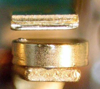
I don't think I lost any sleep over it but it WAS
an interesting study. The really buggy thing about it
was the tiny amount of damage to contacts that were
sticking. This was a really low energy event with some
magic signature as yet un-identified.
[img]cid:.0[/img]
The hardest part of the study was to get the problem
to duplicate on the bench. All the relay suppliers
were stumped. I worked on it for about a year and
a half (part time . . . skunk werks in my basement)
and getting a lot of inconclusive measurements off
the airplane before I decided to try duplicating the
wiring in the airplane. THEN things started to happen.
http://tinyurl.com/pstsggm
After that, it was a matter of sifting the physics. Even
after I began to get the relays to stick on the bench,
it was probably another several months before I was
able to put all the pieces together. These kinds
of things seldom jump off the bench and into your
lap.
| Quote: | Zeners:
Others have suggested the use of a bi-directional Zener. What is the benefit, either theoretical or actual, of using such a device? I'm not clear on what benefit the Zener provides nor do I understand what bi-directional buys you.
(In your answer please speak slowly and use small words;)
|
[img]cid:.1[/img]
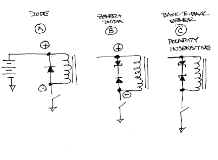
The 'plain vanilla' approach (A) clamps the coil collapse
EMF off at about 1/2 volt (junction drop of the simple
diode). Time constant for current in an inductor is T = L/R.
Effective R of simple diode+coil is lowest; hence T is longest.
A single zener can be added to raise clamping voltage to
a higher level and raising the L/R time constant.
To make this work, the zener wants to be reverse biased
during spike time. A diode must be included to prevent
the zener from being forward biased when the relay is
energized as in (B).
Any time (A) or (B) is built into the suppressed
device, the coil terminals become polarity sensitive.
and (+) terminal must be marked and observed by the
installer.
In (C) we see two zeners back to back. In this case,
spike energy is clamped off at the same voltage but
the network can be included inside the device without
having to observe polarity of coil connections.
You can purchase two-junction transient suppressors
as 'bi-directional' devices.
http://tinyurl.com/kobtg8o
Bob . . .
| | - The Matronics AeroElectric-List Email Forum - | | | Use the List Feature Navigator to browse the many List utilities available such as the Email Subscriptions page, Archive Search & Download, 7-Day Browse, Chat, FAQ, Photoshare, and much more:
http://www.matronics.com/Navigator?AeroElectric-List |
|
| Description: |
|
| Filesize: |
91.04 KB |
| Viewed: |
1596 Time(s) |

|
| Description: |
|
| Filesize: |
38.53 KB |
| Viewed: |
1596 Time(s) |

|
|
|
| Back to top |
|
 |
jluckey(at)pacbell.net
Guest
|
 Posted: Sun Nov 24, 2013 10:25 am Post subject: A clarification on relay/contactor coil suppression Posted: Sun Nov 24, 2013 10:25 am Post subject: A clarification on relay/contactor coil suppression |
 |
|
Bob,
The Zener clamps the flyback voltage at a point higher than a plain vanilla diode - got it. And the double Zener makes for a polarity in-sensitive circuit. That's what I figured but it seemed trivial. I guess it makes for fewer installation errors??
I have attached a spec sheet for a Tyco power relay. In the lower right hand corner of the first page is a wiring diagram. In that diagram, the lower diode seems superfluous to me - so I'm obviously missing something...
OK, just figured it out. The second (lower) diode is for reverse current protection. In case someone hooks it up backwards it won't pop the other diode - it just won't work. (I was going to delete this paragraph, but decided to leave it because someone else might have the same question)
Bob, thanks for taking the time to explain - it's truly appreciated.
-Jeff
From: "Robert L. Nuckolls, III" <nuckolls.bob(at)aeroelectric.com>
To: aeroelectric-list(at)matronics.com
Sent: Saturday, November 23 -, 2013 2:09 PM
Subject: Re: AeroElectric-List: A clarification on relay/contactor coil suppression
How the hell did you figure that out? (did it require sacrificing a chicken or a deal with the devil? -- or was it Divine Inspiration?) Sometimes I have to chase down some pretty hairy bugs in software but that arcing problem would have kept me up at night.
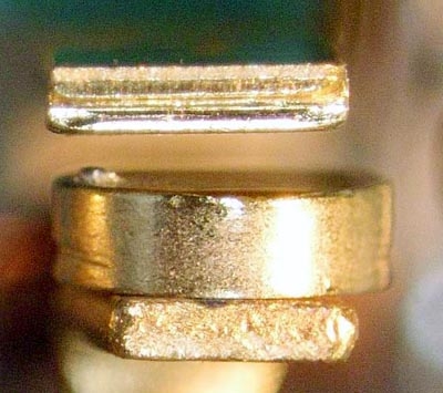
I don't think I lost any sleep over it but it WAS
an interesting study. The really buggy thing about it
was the tiny amount of damage to contacts that were
sticking. This was a really low energy event with some
magic signature as yet un-identified.
[img]cid:1.1226980407(at)web184904.mail.gq1.yahoo.com[/img]
The hardest part of the study was to get the problem
to duplicate on the bench. All the relay suppliers
were stumped. I worked on it for about a year and
a half (part time . . . skunk werks in my basement)
and getting a lot of inconclusive measurements off
the airplane before I decided to try duplicating the
wiring in the airplane. THEN things started to happen.
http://tinyurl.com/pstsggm
After that, it was a matter of sifting the physics. Even
after I began to get the relays to stick on the bench,
it was probably another several months before I was
able to put all the pieces together. These kinds
of things seldom jump off the bench and into your
lap.
| Quote: | Zeners:
Others have suggested the use of a bi-directional Zener. What is the benefit, either theoretical or actual, of using such a device? I'm not clear on what benefit the Zener provides nor do I understand what bi-directional buys you.
(In your answer please speak slowly and use small words;)
|
[img]cid:2.1226980407(at)web184904.mail.gq1.yahoo.com[/img]
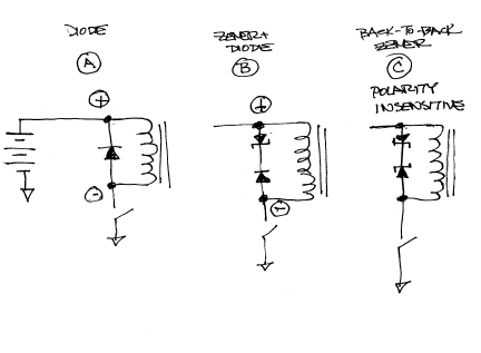
The 'plain vanilla' approach (A) clamps the coil collapse
EMF off at about 1/2 volt (junction drop of the simple
diode). Time constant for current in an inductor is T = L/R.
Effective R of simple diode+coil is lowest; hence T is longest.
A single zener can be added to raise clamping voltage to
a higher level and raising the L/R time constant.
To make this work, the zener wants to be reverse biased
during spike time. A diode must be included to prevent
the zener from being forward biased when the relay is
energized as in (B).
Any time (A) or (B) is built into the suppressed
device, the coil terminals become polarity sensitive.
and (+) terminal must be marked and observed by the
installer.
In (C) we see two zeners back to back. In this case,
spike energy is clamped off at the same voltage but
the network can be included inside the device without
having to observe polarity of coil connections.
You can purchase two-junction transient suppressors
as 'bi-directional' devices.
http://tinyurl.com/kobtg8o
Bob . . .
| | - The Matronics AeroElectric-List Email Forum - | | | Use the List Feature Navigator to browse the many List utilities available such as the Email Subscriptions page, Archive Search & Download, 7-Day Browse, Chat, FAQ, Photoshare, and much more:
http://www.matronics.com/Navigator?AeroElectric-List |
|
| Description: |
|
| Filesize: |
91.04 KB |
| Viewed: |
1587 Time(s) |

|
| Description: |
|
| Filesize: |
38.53 KB |
| Viewed: |
1587 Time(s) |

|
| Description: |
|

Download |
| Filename: |
pwr_relay2.pdf |
| Filesize: |
81.95 KB |
| Downloaded: |
1030 Time(s) |
|
|
| Back to top |
|
 |
nuckolls.bob(at)aeroelect
Guest
|
 Posted: Sun Nov 24, 2013 1:44 pm Post subject: A clarification on relay/contactor coil suppression Posted: Sun Nov 24, 2013 1:44 pm Post subject: A clarification on relay/contactor coil suppression |
 |
|
| Quote: | OK, just figured it out. The second (lower) diode is for reverse
current protection. In case someone hooks it up backwards it won't
pop the other diode - it just won't work. (I was going to delete
this paragraph, but decided to leave it because someone else might
have the same question)
|
Excellent supposition! It's always a challenge
to reverse-guess the motives of the designer when
you discover such features that are not explained
in the catalong. Your idea sounds more plausible
than the first thing that popped into my head:
A few months ago I was digging through a relay
catalog and found a similar circuit for a relay
with an AC coil rating. In this case, the series diode
provided half-wave rectification while the parallel
diode offered a purposeful delay of dropout between
half cycles.
In the case of 60HZ AC, the relay inductance gets
"charged" for 1/120th second every 1/60th second.
If the L/R time constant for decay of coil current
is long enough, then the parallel diode offers the
same 'smoothing' effects on the rectified AC as
a capacitor but much smaller, less expensive and
exploits the energy storage abilities of the inductor.
Isn't this stuff fun?
Bob . . .
| | - The Matronics AeroElectric-List Email Forum - | | | Use the List Feature Navigator to browse the many List utilities available such as the Email Subscriptions page, Archive Search & Download, 7-Day Browse, Chat, FAQ, Photoshare, and much more:
http://www.matronics.com/Navigator?AeroElectric-List |
|
|
|
| Back to top |
|
 |
|
|
You cannot post new topics in this forum
You cannot reply to topics in this forum
You cannot edit your posts in this forum
You cannot delete your posts in this forum
You cannot vote in polls in this forum
You cannot attach files in this forum
You can download files in this forum
|
Powered by phpBB © 2001, 2005 phpBB Group
|


