 |
Matronics Email Lists
Web Forum Interface to the Matronics Email Lists
|
| View previous topic :: View next topic |
| Author |
Message |
donjohnston
Joined: 13 Dec 2009
Posts: 231
|
 Posted: Tue Dec 13, 2016 3:48 pm Post subject: Trim position sensor Posted: Tue Dec 13, 2016 3:48 pm Post subject: Trim position sensor |
 |
|
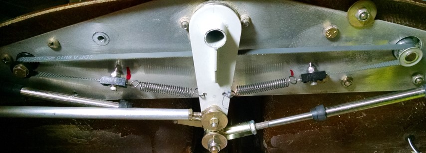
I'm looking for some idea on how to implement a trim position sensor.


Attached is a picture of the aileron trim mechanism.


DC motor on the right drives a cogged belt with an idler pulley on the left. There is no limiter on the motor. It can run continuously.  When it is unable to pull the bellcrank, the belt begins slipping.


The mechanism works fine.  I'm not looking for a new trim mechanism.


But I would like to know where the system is positioned.  I thought about a small magnet on the belt and then some type of sensor but I think that would be too coarse.


So I'm wondering if anyone has any ideas on how to implement a sensor.
| | - The Matronics AeroElectric-List Email Forum - | | | Use the List Feature Navigator to browse the many List utilities available such as the Email Subscriptions page, Archive Search & Download, 7-Day Browse, Chat, FAQ, Photoshare, and much more:
http://www.matronics.com/Navigator?AeroElectric-List |
|
| Description: |
|
| Filesize: |
202.51 KB |
| Viewed: |
3691 Time(s) |

|
|
|
| Back to top |
|
 |
user9253
Joined: 28 Mar 2008
Posts: 1927
Location: Riley TWP Michigan
|
 Posted: Tue Dec 13, 2016 7:19 pm Post subject: Re: Trim position sensor Posted: Tue Dec 13, 2016 7:19 pm Post subject: Re: Trim position sensor |
 |
|
If you fastened a magnet to the belt, mount many magnetic reed switches side by side (glass touching glass) so that at least one switch will always be activated.

25 switches (part number 934-FLEX-14-20-25) cost about $10 total at Mouser.

Reed switches are most easily activated when the magnet is parallel to the switch.  In other words, the magnet north pole is near one end of the switch and the south pole is near the other end of the switch.  A bar magnet should lay flat on the belt with its axis perpendicular to the length of the belt.

  Perhaps others can design a circuit to convert switch closure to panel display.
| | - The Matronics AeroElectric-List Email Forum - | | | Use the List Feature Navigator to browse the many List utilities available such as the Email Subscriptions page, Archive Search & Download, 7-Day Browse, Chat, FAQ, Photoshare, and much more:
http://www.matronics.com/Navigator?AeroElectric-List |
|
_________________
Joe Gores |
|
| Back to top |
|
 |
user9253
Joined: 28 Mar 2008
Posts: 1927
Location: Riley TWP Michigan
|
 Posted: Mon Dec 19, 2016 6:59 am Post subject: Re: Trim position sensor Posted: Mon Dec 19, 2016 6:59 am Post subject: Re: Trim position sensor |
 |
|
Install another bellcrank with its lower end attached to the outboard end of one of the springs.  Connect a Ray Allen position sensor to the new bellcrank at a point that matches the travel requirements.

Or drive the new bellcrank with a Ray Allen servo (with built-in sensor and limit switches).  Replace the existing motor drive gear with an idler gear.
| | - The Matronics AeroElectric-List Email Forum - | | | Use the List Feature Navigator to browse the many List utilities available such as the Email Subscriptions page, Archive Search & Download, 7-Day Browse, Chat, FAQ, Photoshare, and much more:
http://www.matronics.com/Navigator?AeroElectric-List |
|
_________________
Joe Gores |
|
| Back to top |
|
 |
|
|
You cannot post new topics in this forum
You cannot reply to topics in this forum
You cannot edit your posts in this forum
You cannot delete your posts in this forum
You cannot vote in polls in this forum
You cannot attach files in this forum
You can download files in this forum
|
Powered by phpBB © 2001, 2005 phpBB Group
|


