 |
Matronics Email Lists
Web Forum Interface to the Matronics Email Lists
|
| View previous topic :: View next topic |
| Author |
Message |
nuckolls.bob(at)aeroelect
Guest
|
 Posted: Wed Jun 27, 2018 6:55 pm Post subject: DC motors Posted: Wed Jun 27, 2018 6:55 pm Post subject: DC motors |
 |
|
I've had a couple of queries about observed motor

 behaviors wherein the writer was certain they

 observed situations where motors struggling under

 low voltage caused protection devices to operate.


 It's easy to characterize the physics of a DC motor.

 A motor reveals most of its secrets when you measure

 three characteristics: (1) The motor's DC resistance;

 it's torque constant (Kt) wherein you measure the

 output torque when excited by some value of test

 current. From this you can derive In-Oz of torque

 per amp of current draw; (3) the counter EMF constant

 (Ke) in RPM/Volt by spinning the motor at some known

 RPM and measuring the motor's output voltage as

 a generator.


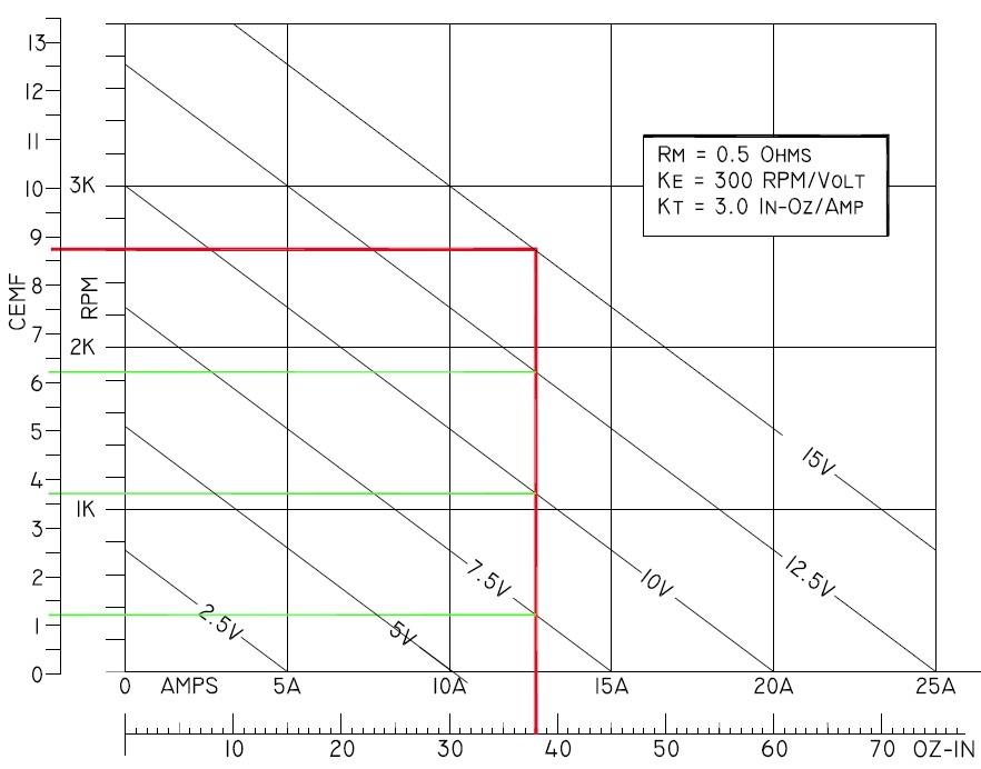
 Once you have these three numbers you can construct

 a plot of motor performance at various voltages. An exemplar

 plot is shown below:


 [img]cid:.0[/img]


 Applying 10V to this hypothetical motor with a locked rotor

 would produce a stall current of 20 amps. If a torque watch

 were attached to the immobilized shaft it would read 60 in-oz.

 This experiment yields a motor resistance of 0.5 ohms and

 Kt - 3.0 in-oz/amp.


 Okay, now spin hte motor with a drill motor. Measure the

 RPM and voltage at the power leads. In this case we would

 find that the motor 'generates' 1.0 volts per 300 RPM

 of the shaft. This number lets us put a counter-emf scale

 alongside the RPM scale.


 Note that the family of voltage lines are parallel

 to each other. The SLOPE of these lines is proportional

 to the motor's DC resistance. If the motor's resistance

 were 1.0 ohms, then stall current at the lower end of each

 voltage line would be 1/2 that presently illustrated.

 I.e. a new family of lines having 2x the slope of the

 0.5 ohm lines shown.


 Let's take a hypothetical application where we operate

 this motor at 15.0 volts applied and a load of 38 in-oz.

 The plotted characteristics tells us that the motor will

 run at 2600 RPM and draw a current of about 12.6 Amps.

 15 Volts applied across an Rm = 0.5 ohms yields an inrush

 current of 30A . . . which could be added to the plot

 above if I extended it another 5A to the right.


 You can pick any spot on the face of the plot, draw a 0.5

 ohm load line thorough it and you have a new applied voltage,

 running current, RPM and stall current.


 But without increasing the load on the motor shaft, there

 is no way we can make the motor draw MORE current by

 reducing its applied voltage.


   Bob . . .
| | - The Matronics AeroElectric-List Email Forum - | | | Use the List Feature Navigator to browse the many List utilities available such as the Email Subscriptions page, Archive Search & Download, 7-Day Browse, Chat, FAQ, Photoshare, and much more:
http://www.matronics.com/Navigator?AeroElectric-List |
|
| Description: |
|
| Filesize: |
165.97 KB |
| Viewed: |
1429 Time(s) |

|
|
|
| Back to top |
|
 |
bob.verwey(at)gmail.com
Guest
|
 Posted: Thu Jun 28, 2018 4:43 am Post subject: DC motors Posted: Thu Jun 28, 2018 4:43 am Post subject: DC motors |
 |
|
Bob thanks for that very coherent expose of the dark secrets of DC motors <lol>
Neophytes such as I benefit greatly from your missives...
Best...Bob Verwey
082 331 2727
[img]https://docs.google.com/uc?export=download&id=0B5d7rgAInTuTUUZsUjY4QmJsdVU&revid=0B5d7rgAInTuTdDJDaXRFZVh3b3lMa3FWL0s3MFdzc01YRlNvPQ[/img]
On 28 June 2018 at 04:54, Robert L. Nuckolls, III <nuckolls.bob(at)aeroelectric.com (nuckolls.bob(at)aeroelectric.com)> wrote:
| Quote: | I've had a couple of queries about observed motor
behaviors wherein the writer was certain they
observed situations where motors struggling under
low voltage caused protection devices to operate.
It's easy to characterize the physics of a DC motor.
A motor reveals most of its secrets when you measure
three characteristics: (1) The motor's DC resistance;
it's torque constant (Kt) wherein you measure the
output torque when excited by some value of test
current. From this you can derive In-Oz of torque
per amp of current draw; (3) the counter EMF constant
(Ke) in RPM/Volt by spinning the motor at some known
RPM and measuring the motor's output voltage as
a generator.
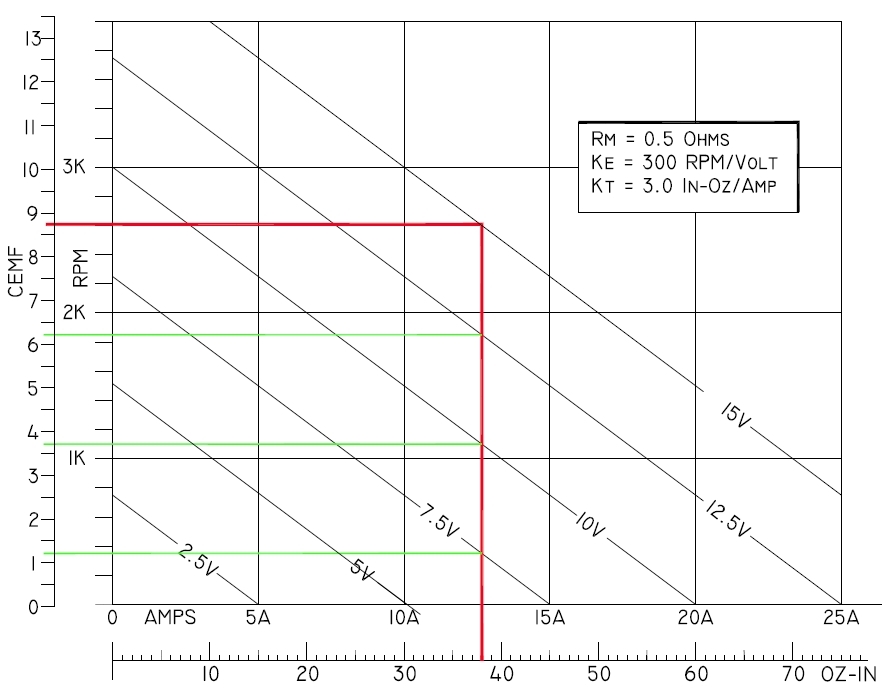
Once you have these three numbers you can construct
a plot of motor performance at various voltages. An exemplar
plot is shown below:
[img]cid:.0[/img]
Applying 10V to this hypothetical motor with a locked rotor
would produce a stall current of 20 amps. If a torque watch
were attached to the immobilized shaft it would read 60 in-oz.
This experiment yields a motor resistance of 0.5 ohms and
Kt - 3.0 in-oz/amp.
Okay, now spin hte motor with a drill motor. Measure the
RPM and voltage at the power leads. In this case we would
find that the motor 'generates' 1.0 volts per 300 RPM
of the shaft. This number lets us put a counter-emf scale
alongside the RPM scale.
Note that the family of voltage lines are parallel
to each other. The SLOPE of these lines is proportional
to the motor's DC resistance. If the motor's resistance
were 1.0 ohms, then stall current at the lower end of each
voltage line would be 1/2 that presently illustrated.
I.e. a new family of lines having 2x the slope of the
0.5 ohm lines shown.
Let's take a hypothetical application where we operate
this motor at 15.0 volts applied and a load of 38 in-oz.
The plotted characteristics tells us that the motor will
run at 2600 RPM and draw a current of about 12.6 Amps.
15 Volts applied across an Rm = 0.5 ohms yields an inrush
current of 30A . . . which could be added to the plot
above if I extended it another 5A to the right.
You can pick any spot on the face of the plot, draw a 0.5
ohm load line thorough it and you have a new applied voltage,
running current, RPM and stall current.
But without increasing the load on the motor shaft, there
is no way we can make the motor draw MORE current by
reducing its applied voltage.
Bob . . .
|
| | - The Matronics AeroElectric-List Email Forum - | | | Use the List Feature Navigator to browse the many List utilities available such as the Email Subscriptions page, Archive Search & Download, 7-Day Browse, Chat, FAQ, Photoshare, and much more:
http://www.matronics.com/Navigator?AeroElectric-List |
|
| Description: |
|
| Filesize: |
165.97 KB |
| Viewed: |
1426 Time(s) |

|
|
|
| Back to top |
|
 |
|
|
You cannot post new topics in this forum
You cannot reply to topics in this forum
You cannot edit your posts in this forum
You cannot delete your posts in this forum
You cannot vote in polls in this forum
You cannot attach files in this forum
You can download files in this forum
|
Powered by phpBB © 2001, 2005 phpBB Group
|


