 |
Matronics Email Lists
Web Forum Interface to the Matronics Email Lists
|
| View previous topic :: View next topic |
| Author |
Message |
farmrjohn
Joined: 31 Dec 2018
Posts: 54
|
 Posted: Wed Sep 02, 2020 1:32 pm Post subject: AV 30 Wiring Posted: Wed Sep 02, 2020 1:32 pm Post subject: AV 30 Wiring |
 |
|
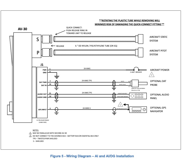
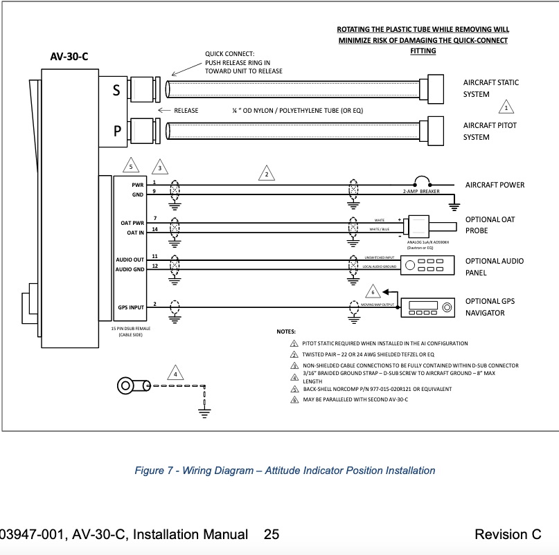
Now that the AV 30 has STC approval for certificated airplanes I have some questions on the wiring differences.


The experimental say power is to be from the battery or essential bus only, the "approved" manual says power is from the avionics bus or main master relay.  Can the experimental version also be powered from the avionics bus?


The certified calls for a 3/16" braided ground strap from the of the d-sub back shell, maximum of 8".  What would be a similar sized stranded wire, and would the also be a good idea for the experimental version?


On the wiring diagrams some of the shielded wire symbols have an X in them.  Does this indicate twisted pair?
| | - The Matronics AeroElectric-List Email Forum - | | | Use the List Feature Navigator to browse the many List utilities available such as the Email Subscriptions page, Archive Search & Download, 7-Day Browse, Chat, FAQ, Photoshare, and much more:
http://www.matronics.com/Navigator?AeroElectric-List |
|
| Description: |
|
| Filesize: |
92.45 KB |
| Viewed: |
3153 Time(s) |

|
| Description: |
|
| Filesize: |
122.07 KB |
| Viewed: |
3153 Time(s) |

|
|
|
| Back to top |
|
 |
farmrjohn
Joined: 31 Dec 2018
Posts: 54
|
 Posted: Tue Sep 08, 2020 3:21 pm Post subject: Re: AV 30 Wiring Posted: Tue Sep 08, 2020 3:21 pm Post subject: Re: AV 30 Wiring |
 |
|
Bump, primarily to re-ask the question about the diagrams with the "X" in the shield symbol. Thanks, John
| | - The Matronics AeroElectric-List Email Forum - | | | Use the List Feature Navigator to browse the many List utilities available such as the Email Subscriptions page, Archive Search & Download, 7-Day Browse, Chat, FAQ, Photoshare, and much more:
http://www.matronics.com/Navigator?AeroElectric-List |
|
|
|
| Back to top |
|
 |
nuckolls.bob(at)aeroelect
Guest
|
 Posted: Tue Sep 08, 2020 5:28 pm Post subject: AV 30 Wiring Posted: Tue Sep 08, 2020 5:28 pm Post subject: AV 30 Wiring |
 |
|
At 06:21 PM 9/8/2020, you wrote:
| Quote: | --> AeroElectric-List message posted by: "farmrjohn" <faithvineyard(at)yahoo.com>
Bump, primarily to re-ask the question about the diagram for the certified version with the "X" in the shield symbol. Thanks, John |
I would infer that to indicate twisted conductors . . .
but then I think one would be hard pressed to find
a shielded pair that was not twisted.
Bob . . .
| | - The Matronics AeroElectric-List Email Forum - | | | Use the List Feature Navigator to browse the many List utilities available such as the Email Subscriptions page, Archive Search & Download, 7-Day Browse, Chat, FAQ, Photoshare, and much more:
http://www.matronics.com/Navigator?AeroElectric-List |
|
|
|
| Back to top |
|
 |
donjohnston
Joined: 13 Dec 2009
Posts: 231
|
 Posted: Wed Sep 09, 2020 1:28 pm Post subject: Re: AV 30 Wiring Posted: Wed Sep 09, 2020 1:28 pm Post subject: Re: AV 30 Wiring |
 |
|
I would agree.  On the second drawing, the only place TPS is shown is on those wires with the "X".


Although it does appear the shields are grounded in two places.  I thought the idea was to always ground the shield at one end.
| | - The Matronics AeroElectric-List Email Forum - | | | Use the List Feature Navigator to browse the many List utilities available such as the Email Subscriptions page, Archive Search & Download, 7-Day Browse, Chat, FAQ, Photoshare, and much more:
http://www.matronics.com/Navigator?AeroElectric-List |
|
|
|
| Back to top |
|
 |
nuckolls.bob(at)aeroelect
Guest
|
 Posted: Thu Sep 10, 2020 7:32 am Post subject: AV 30 Wiring Posted: Thu Sep 10, 2020 7:32 am Post subject: AV 30 Wiring |
 |
|
At 04:28 PM 9/9/2020, you wrote:
| Quote: | --> AeroElectric-List message posted by: "donjohnston" <don(at)velocity-xl.com>
I would agree. On the second drawing, the only place TPS is shown is on those wires with the "X".
Although it does appear the shields are grounded in two places. I thought the idea was to always ground the shield at one end. |
Yes . . . but.
If the design goal for shielding wires
is to BREAK and electro-static coupling
mode between potential antagonist/victim
wires, then yes . . . connect shield to
one ground only.
SOME installations exploit the shield as
part of the energy management goal. One
example can be seen in the Z-figures where
I recommend GROUNDING a p-lead shield at
the magneto end then using the shield
to provide a GROUND PATH for the switch
at the other end. Some authors have
suggested that p-leads need to be shield
grounded at BOTH ends which has no foundation
in physics and raises risks for some ground
loop issues.
I've also used the shield as a return
path for incandescent bulbs illuminating
a whisky compass. Providing a coaxially
concentric out-and-back path for bulb
currents cancels magnetic fields around
the wire and prevents illumination induced
heading errors.
The best thing to do is follow the
manufacturer's installation instructions.
I cannot assert they are always 'golden'
but there just might be a good reason
for doubling up shield terminations.
Bob . . .
| | - The Matronics AeroElectric-List Email Forum - | | | Use the List Feature Navigator to browse the many List utilities available such as the Email Subscriptions page, Archive Search & Download, 7-Day Browse, Chat, FAQ, Photoshare, and much more:
http://www.matronics.com/Navigator?AeroElectric-List |
|
|
|
| Back to top |
|
 |
|
|
You cannot post new topics in this forum
You cannot reply to topics in this forum
You cannot edit your posts in this forum
You cannot delete your posts in this forum
You cannot vote in polls in this forum
You cannot attach files in this forum
You can download files in this forum
|
Powered by phpBB © 2001, 2005 phpBB Group
|


