 |
Matronics Email Lists
Web Forum Interface to the Matronics Email Lists
|
| View previous topic :: View next topic |
| Author |
Message |
chris Sinfield
Joined: 28 Nov 2006
Posts: 270
Location: Sydney Australia
|
 Posted: Tue Jul 17, 2007 2:03 pm Post subject: XL photo guide help Posted: Tue Jul 17, 2007 2:03 pm Post subject: XL photo guide help |
 |
|
Hi Gang

Its late and I am revisiting an old area on the firewall but cant fing the photo gudes to check somthing.


Where is the photo guide on the lower nose bearing instalation located??


Are they bolts with nuts or just bolts into the plastic???


Also

Confirm the Stop Plate at the top of the nose strut should not be touching the horizontal plate when full extended but the steering arms should be centered fully down in the groove when the weight is off the ground.


Ie the Strut Weight is taken from the botom nose bearing not the stop plate when airborne.


Chris Zodiac XL
| | - The Matronics Zenith-List Email Forum - | | | Use the List Feature Navigator to browse the many List utilities available such as the Email Subscriptions page, Archive Search & Download, 7-Day Browse, Chat, FAQ, Photoshare, and much more:
http://www.matronics.com/Navigator?Zenith-List |
|
|
|
| Back to top |
|
 |
eddies
Joined: 20 Jun 2006
Posts: 40
Location: Australia
|
| Posted: Tue Jul 17, 2007 2:25 pm Post subject: Re: XL photo guide help |
|
|
Hi Chris,


The bolts are threaded directly into the black plastic, you'll need to tap the thread first of course.


Yes the weight is taken by the bottom bearing, there is a gap between the top stop plate and top firewall stiffener. Once you attach the bungie this will become immediately obvious.


Eddie
| | - The Matronics Zenith-List Email Forum - | | | Use the List Feature Navigator to browse the many List utilities available such as the Email Subscriptions page, Archive Search & Download, 7-Day Browse, Chat, FAQ, Photoshare, and much more:
http://www.matronics.com/Navigator?Zenith-List |
|
|
|
| Back to top |
|
|
dredmoody(at)cox.net
Guest
|
| Posted: Tue Jul 17, 2007 2:52 pm Post subject: XL photo guide help |
|
|
Chris, I didn't find anything in the photo assembly guide regarding the nose strut either. I just worked form the drawings and they indicate ANH4-6A bolts(drilled heads for safetty wire) through the aluminum support threaded into the plastic. There are four of them. You backdrill through the aluminum into the plastic at the correct drill size for a 1/4" x 28 tap. Once the holes are drilled, you enlarge the ones in the aluminum only to 1/4" diameter. I also found that AN4H-5A would be a better bolt size. These don't have to be extremely tight since they will be safety wired and function mostly in shear strength.
There are two long bolts, AN3-42 , which clamp the two halves of the plastic block together and once again, the forward one should be AN3-41 since it doesn't have any aluminum channel to go through like the aft one does. There is a predjudice against more than four washers on a bolt.
As for the upper stop plate, mine seems to be in contact at about the same point as the steering arms on the lower block.
My nose strut seems tighter in the plastic block than it neeeds to be so I am wondering if it is okay to sand inside the plastic block or place a thin shim between the halves to lighten up the clamping force there.
Dred
---- chris Sinfield <chris_sinfield(at)yahoo.com.au> wrote: > Where is the photo guide on the lower nose bearing instalation located??
| Quote: |
Are they bolts with nuts or just bolts into the plastic???
|
| | - The Matronics Zenith-List Email Forum - | | | Use the List Feature Navigator to browse the many List utilities available such as the Email Subscriptions page, Archive Search & Download, 7-Day Browse, Chat, FAQ, Photoshare, and much more:
http://www.matronics.com/Navigator?Zenith-List |
|
|
|
| Back to top |
|
|
ding(at)tbscc.com
Guest
|
| Posted: Tue Jul 17, 2007 3:53 pm Post subject: XL photo guide help |
|
|
Dred,

            Wright or wrong, I made custom shims for mine and was able to

get the proper fit. I also had to use a band sander on the tube to make it

round again. It had warped a bit oval when welded. If this unit binds, it

will of course adversly affect rudder operation.


                            Lynn


                            601 XL / Corvair      70%


---
| | - The Matronics Zenith-List Email Forum - | | | Use the List Feature Navigator to browse the many List utilities available such as the Email Subscriptions page, Archive Search & Download, 7-Day Browse, Chat, FAQ, Photoshare, and much more:
http://www.matronics.com/Navigator?Zenith-List |
|
|
|
| Back to top |
|
|
dredmoody(at)cox.net
Guest
|
| Posted: Tue Jul 17, 2007 5:03 pm Post subject: XL photo guide help |
|
|
Thanks Lynn. I was primarily concerned about having stiff rudder movement. I'll shim the lower block until it feels easy to turn.
Dred
Do Not Archive
---- Dingfelder <ding(at)tbscc.com> wrote:
| Quote: |
Dred,
Wright or wrong, I made custom shims for mine and was able to
get the proper fit. I also had to use a band sander on the tube to make it
round again. It had warped a bit oval when welded. If this unit binds, it
will of course adversly affect rudder operation.
|
| | - The Matronics Zenith-List Email Forum - | | | Use the List Feature Navigator to browse the many List utilities available such as the Email Subscriptions page, Archive Search & Download, 7-Day Browse, Chat, FAQ, Photoshare, and much more:
http://www.matronics.com/Navigator?Zenith-List |
|
|
|
| Back to top |
|
|
craig(at)craigandjean.com
Guest
|
| Posted: Tue Jul 17, 2007 5:11 pm Post subject: XL photo guide help |
|
|
I searched long and hard through the photo assembly guides for some shots of
the nose gear V-block. Never did find one. The only mention of this in the
plans that I could find was on 6G2. On the 08/05 revision the upper left
corner says "bolt pattern see drawing 6B8-9. 4 holes tapped". The lower
right corner says "AN4H-5A (4 req'd) 2 bolts per side, safety together".
I didn't want to drill all the way through the block and leave a hole on the
upper side that would hold dirt, water, etc. So I drilled blind holes on a
drill press. This would be hard to do with a hand drill as the bit really
catches on the nylon. This means you have to tap blind holes. The way that
mine laid out the two rear holes were in the full thickness of the block. So
I was able to drill these holes deeper than the bolt's length and use a
conventional 1/4-28 fine tap. But there wasn't enough thickness to do this
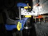
on the two forward holes. Here you need a blind tap. Three ways to get one:
buy (expensive and hard-ish to find), break the tip off of a conventional
tap (mine came in a two-pack) or cut groves in a 1/4-28 bolt with a fine
cut-off wheel in a Dremel tool (picture attached). I've attached a picture
of the results from Lance Gringell's plane.
Scott Laughlin (I think) took a different approach. He drill the holes all
the way through the blocks and inserted the bolts from the top. He
countersunk the holes on the top so that bolt heads were below the surface
of the V. Then he just used nyloc nuts on the bottom. I think he used the
holes as grease cups.
A few other points:
1. In order to get my nose gear tube as parallel to the firewall as possible
I had to butt the back of the V-block against the firewall. Since I pulled
the bottom three rivets on the firewall gear stiffener U channel from the
inside of the plane I had to drill three clearance holes in the back of the
V-block for the stubs of the rivets. A digital level makes it easy to see
how parallel the tube is to the firewall.
2. The gap between the horizontal steel tube that retains the bungee (6G2-2)
and the nose wheel tube is very small (2 mm?). And the bungee wants to pull
those two pieces together. If there is too much accumulated error in the
firewall parts the horizontal tube scrapes on the nose gear tube. That the
way my kits was when I acquired it. Luckily (?) I rebuilt the old-style
firewall with the new-style stiffeners and was able to correct this.
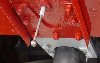
3. The cross tube on the nose gear was not perfectly parallel to the nose
gear axle. Before I drilled the hole in the gear U channel that receives the
long horizontal bolt through the V-block I made sure the axle was square. I
did this by clamping the cross-tube into the V and inserting a long rod
through the axle holes. With the rod centered I measured the distance of the
ends from the rudder's pivot hole (picture attached).
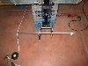
To know where to drill holes in the U channel which lined up with the
existing hole in the V-block I pre-built a pair of "blinders" or transfer
gauges. See image 204 attached.
Of course you have to do this before you drill the holes for the four bolts
that enter the V block from the bottom. In theory the cross tube is not in
the V when the plan is on the ground as the engine's weight stretches the
bungee and lifts the tube out of the V. But I have seen planes on the ground
with the tube in the V. Maybe it lifts out when the plane is loaded with
people, etc. But lining things up does ensure that your nose wheel fairing
will be true in flight with your feet off the rudder pedals.
I refuse to say how many tries it took me to get all this right.
-- Craig
| | - The Matronics Zenith-List Email Forum - | | | Use the List Feature Navigator to browse the many List utilities available such as the Email Subscriptions page, Archive Search & Download, 7-Day Browse, Chat, FAQ, Photoshare, and much more:
http://www.matronics.com/Navigator?Zenith-List |
|
| Description: |
|
| Filesize: |
14.6 KB |
| Viewed: |
297 Time(s) |

|
| Description: |
|
| Filesize: |
35.02 KB |
| Viewed: |
336 Time(s) |
|
| Description: |
|
| Filesize: |
43.4 KB |
| Viewed: |
311 Time(s) |
|
| Description: |
|
| Filesize: |
43.53 KB |
| Viewed: |
315 Time(s) |
|
|
|
| Back to top |
|
|
dredmoody(at)cox.net
Guest
|
| Posted: Wed Jul 18, 2007 10:26 am Post subject: XL photo guide help |
|
|
It should be okay to drill those holes all the way through the plastic block making it easier to tap them. Then simply put a dab of RTV silicone to close off the top after assembly.
Dred
---- Craig Payne <craig(at)craigandjean.com> wrote: > I didn't want to drill all the way through the block and leave a hole on the
| Quote: | upper side that would hold dirt, water, etc.
|
| | - The Matronics Zenith-List Email Forum - | | | Use the List Feature Navigator to browse the many List utilities available such as the Email Subscriptions page, Archive Search & Download, 7-Day Browse, Chat, FAQ, Photoshare, and much more:
http://www.matronics.com/Navigator?Zenith-List |
|
|
|
| Back to top |
|
|
|
|
You cannot post new topics in this forum
You cannot reply to topics in this forum
You cannot edit your posts in this forum
You cannot delete your posts in this forum
You cannot vote in polls in this forum
You cannot attach files in this forum
You can download files in this forum
|
Powered by phpBB © 2001, 2005 phpBB Group
|

