 |
Matronics Email Lists
Web Forum Interface to the Matronics Email Lists
|
| View previous topic :: View next topic |
| Author |
Message |
doug.ilg(at)verizon.net
Guest
|
 Posted: Tue Apr 13, 2010 2:54 pm Post subject: schematic for a Challenger II Posted: Tue Apr 13, 2010 2:54 pm Post subject: schematic for a Challenger II |
 |
|
Folks,
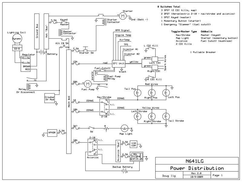
Attached is my schematic diagram for the power distribution in my Challenger II as a 300 dpi .jpg. I tried to send a .sch file from ExpressSCH, but the list software refused it.
Anyway, I started with Z-17, but had to change a few things to accommodate the fuel injection system. This is for a Hirth 3203.
A few notes:
* Pay no attention to wire sizes. I have not really done that analysis. As a general rule, though, I plan to use 20 AWG for most things, with 4 AWG welding cable for the fat wires.
* The Hirth lighting coil is good for about 250W, which is about 21A (at) 12V.
* The switch logic for the small (1.7Ah) backup battery is pretty much as suggested by MGL (the EFIS' manufacturer). I combined it with the power for the radio and EFIS, to save space. I plan to wire it so down is off, middle is backup power and up is ship's power. In the up position, the EFIS will charge the battery. The middle position is really only to check that the battery is working.
* The transponder has a built-in power switch, so it was not ganged with the others.
* The EFIS contains low-voltage warning alert.
* The main battery will be an Odyssey PC625, 16Ah.
* I'll add a filter cap on the VR output, if it becomes necessary.
I think that covers it. Now, I'll sit back and watch the fireworks!
Thanks for checking it out.
-Doug
Doug Ilg
Grumman Tiger N74818, College Park Airport (KCGS), Maryland
Challenger II LSS LW (N641LG reserved) - kit underway at Laurel Suburban (W18)
| | - The Matronics AeroElectric-List Email Forum - | | | Use the List Feature Navigator to browse the many List utilities available such as the Email Subscriptions page, Archive Search & Download, 7-Day Browse, Chat, FAQ, Photoshare, and much more:
http://www.matronics.com/Navigator?AeroElectric-List |
|
| Description: |
|
| Filesize: |
58.44 KB |
| Viewed: |
4723 Time(s) |
|
|
|
| Back to top |
|
 |
user9253
Joined: 28 Mar 2008
Posts: 1921
Location: Riley TWP Michigan
|
| Posted: Wed Apr 14, 2010 6:07 am Post subject: Re: schematic for a Challenger II |
|
|
Doug,

The way to let others open a file is to save it on a file sharing website and then provide a link to it on Matronics.  I use WindowsLive.  Even though it is designed for photo sharing, you are allowed to share files with various extensions.

   4AWG seems big for a small engine unless the battery is a long way from the starter.

   Placing diodes in parallel across the relays and contactors (with arrows pointing towards positive) will protect the controlling switches from arcs and sparks.

   Switching the grounded side of the master contactor instead of the hot side will minimize the number of hot wires running to the instrument panel.

   An avionics switch is not recommended because if it fails, everything connected to it stops working.  In your case, there are only two items.  If each has its own on-off switch, then an avionics switch is not needed.

Joe
| | - The Matronics AeroElectric-List Email Forum - | | | Use the List Feature Navigator to browse the many List utilities available such as the Email Subscriptions page, Archive Search & Download, 7-Day Browse, Chat, FAQ, Photoshare, and much more:
http://www.matronics.com/Navigator?AeroElectric-List |
|
_________________
Joe Gores |
|
| Back to top |
|
|
doug.ilg(at)verizon.net
Guest
|
| Posted: Wed Apr 14, 2010 7:40 am Post subject: schematic for a Challenger II |
|
|
Joe,


Oops.  I guess attaching the file was a faux pas.  Sorry.

Would you say that 6AWG is good enough for the fat wires, then?


Another oops.  I have those diodes across the coils on my diagram.  Sent the wrong one.


Good point on switching the ground side.  Will do.


For the avionics switch, both of the switched units (EFIS and radio) require external switches.  Wish they didn't.  I'll consider separating them if I can find enough room on the relatively small panel.  (The switches I'd like to use are rather large.)


Doug Ilg

Grumman Tiger N74818, College Park Airport (KCGS), Maryland

Challenger II LSS LW (N641LG reserved) - kit underway at Laurel Suburban (W18)
| | - The Matronics AeroElectric-List Email Forum - | | | Use the List Feature Navigator to browse the many List utilities available such as the Email Subscriptions page, Archive Search & Download, 7-Day Browse, Chat, FAQ, Photoshare, and much more:
http://www.matronics.com/Navigator?AeroElectric-List |
|
|
|
| Back to top |
|
|
user9253
Joined: 28 Mar 2008
Posts: 1921
Location: Riley TWP Michigan
|
| Posted: Wed Apr 14, 2010 5:10 pm Post subject: Re: schematic for a Challenger II |
|
|
| Quote: | | I guess attaching the file was a faux pas. |
There is nothing wrong with the way that you did it. I was only trying to explain how to share a drawing with the extension of sch.
| Quote: | | Would you say that 6AWG is good enough for the fat wires, then? |
I do not know. It all depends on the current draw of the starter and length of wire. My Rotax 912 comes with 8awg for the starter. What have others used on your type of plane and engine? You could try smaller wire and if the engine cranks too slowly, then replace the wire with a larger size.
I assume that your plane will be used for low and slow fun flying. As long as failure of the avionics switch does not disable critical equipment, then having one switch for two devices is OK. Separate switches are ideal but one switch will work.
Joe
| | - The Matronics AeroElectric-List Email Forum - | | | Use the List Feature Navigator to browse the many List utilities available such as the Email Subscriptions page, Archive Search & Download, 7-Day Browse, Chat, FAQ, Photoshare, and much more:
http://www.matronics.com/Navigator?AeroElectric-List |
|
_________________
Joe Gores |
|
| Back to top |
|
|
retasker(at)optonline.net
Guest
|
| Posted: Wed Apr 14, 2010 7:42 pm Post subject: schematic for a Challenger II |
|
|
Why is attaching a file a faux pas? Plenty of others do it. Yours was
quite small as attachments go... Attaching a 5MB file would be, in my
opinion, but an 84K file...
Dick Tasker
Doug Ilg wrote:
| Quote: |
Joe,
Oops. I guess attaching the file was a faux pas. Sorry.
Would you say that 6AWG is good enough for the fat wires, then?
Another oops. I have those diodes across the coils on my diagram. Sent the wrong one.
Good point on switching the ground side. Will do.
For the avionics switch, both of the switched units (EFIS and radio) require external switches. Wish they didn't. I'll consider separating them if I can find enough room on the relatively small panel. (The switches I'd like to use are rather large.)
Doug Ilg
Grumman Tiger N74818, College Park Airport (KCGS), Maryland
Challenger II LSS LW (N641LG reserved) - kit underway at Laurel Suburban (W18)
|
--
Please Note:
No trees were destroyed in the sending of this message. We do concede, however,
that a significant number of electrons may have been temporarily inconvenienced.
--
| | - The Matronics AeroElectric-List Email Forum - | | | Use the List Feature Navigator to browse the many List utilities available such as the Email Subscriptions page, Archive Search & Download, 7-Day Browse, Chat, FAQ, Photoshare, and much more:
http://www.matronics.com/Navigator?AeroElectric-List |
|
|
|
| Back to top |
|
|
|
|
You cannot post new topics in this forum
You cannot reply to topics in this forum
You cannot edit your posts in this forum
You cannot delete your posts in this forum
You cannot vote in polls in this forum
You cannot attach files in this forum
You can download files in this forum
|
Powered by phpBB © 2001, 2005 phpBB Group
|

