mdnanwelch7(at)hotmail.co
Guest
|
 Posted: Thu Nov 25, 2010 2:37 pm Post subject: Dynon alarm detector Posted: Thu Nov 25, 2010 2:37 pm Post subject: Dynon alarm detector |
 |
|
Mr. Bob,


   Regarding the Dynon alarm detector circuit you designed, I have a

 very easy question;  (your circuit is attached, to save you the trouble of

 looking it up)

   First, some background.  As I mentioned awhile back, I intended to use

 your circuit to power a "cascading LED circuit".  (this is a 10 LED

 flashing circuit based on the 555 timer and the 4017 decade counter)

 This would give a visual alarm, in addition to the standard Dynon audio

 alarm.


   I built the entire combo circuit, where the Dynon alarm detector powers

 the cascading LEDs upon activation.  Works great, look nice.  Exactly what

 I had in mind.  However, I would like to verify during preflight inspection that

 the alarm detector is "working" properly (waiting for a signal), although I

 wouldn't know while on the ground .


   Here's the question;  Can I install an SPST switch between the "alarm signal

 wire" and the +12V 'always hot' wire to the detector circuit?  On the breadboard,

 this works just fine...but there is no Dynon hooked up to it, either.  I don't want to

 assume I can start applying +12V to the Dynon alarm signal wire (while it is NOT

 in alarm mode) and everything will be okay.  Do I need to protect the Dynon EFIS

 in order to check the alarm circuit is operable?

   Would a diode be necessary upstream from the switch?  If so, which one.

 What do you think?


   BTW, after building the Dynon alarm detector, I found out not just ANY NPN

 transistors will do.  Evidently the PNP & NPN transistors are somewhat 'matched'.

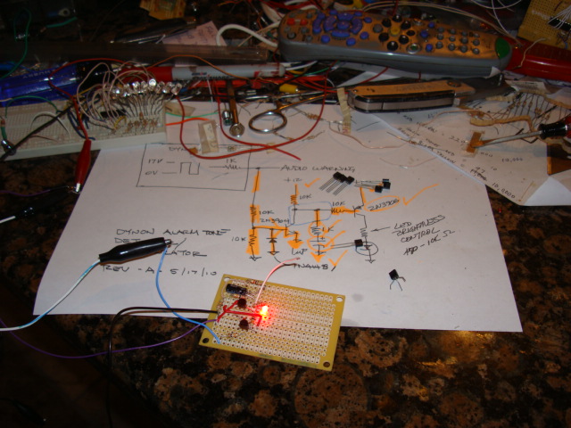
 It matters!!  I had a package of RShack "NPN" transistors.  For the record, BC546's

 don't work!  (You can see it off to the right in the picture of my project)


   Here is a picture of the fully finished Dynon alarm detector circuit.  I installed

 the single 3mm LED, and will leave it in.  The short white wire sends power to the

 'yet to be built' LED circuit.  The completed and operable LED circuit is on the

 breadboard, top left in the picture.  I salvaged some of the Dynon circuit parts

 off the breadboard to build the finished circuit.  The purple wire is the +12V lead.

 The light blue wire is the alarm signal.  Black is ground.  The black aligator clip

 is providing power (artificial alarm signal) to the purple wire charged with +12V.

 Works like a champ!!       I just need to allow for proper checking....


 Thanks for your time,     Mike Welch
| | - The Matronics AeroElectric-List Email Forum - | | | Use the List Feature Navigator to browse the many List utilities available such as the Email Subscriptions page, Archive Search & Download, 7-Day Browse, Chat, FAQ, Photoshare, and much more:
http://www.matronics.com/Navigator?AeroElectric-List |
|
| Description: |
|
| Filesize: |
121.78 KB |
| Viewed: |
1097 Time(s) |

|
| Description: |
|

Download |
| Filename: |
Dynon_Alarm_Tone_Detector_A.pdf |
| Filesize: |
22.05 KB |
| Downloaded: |
121 Time(s) |
|
|


