 |
Matronics Email Lists
Web Forum Interface to the Matronics Email Lists
|
| View previous topic :: View next topic |
| Author |
Message |
nuckolls.bob(at)aeroelect
Guest
|
|
| Back to top |
|
 |
nuckolls.bob(at)aeroelect
Guest
|
 Posted: Mon Feb 21, 2011 2:02 pm Post subject: DIY Over Voltage Protection Posted: Mon Feb 21, 2011 2:02 pm Post subject: DIY Over Voltage Protection |
 |
|
Bob,

 I checked out that bilateral switch from Digikey.  Unfortunately it is

 not stocked and minimum order is 2500 pieces.


   Hmmmm . . . my bad. I jumped on the full range of quanity

   pricing starting with "1" but missed the fact that there

   were none in stock.


 I did find some other interesting devices that could be used in an O.V. protection circuit.


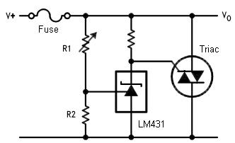
  http://www.fairchildsemi.com/ds/LM/LM431B.pdf used in this circuit:

  http://en.wikipedia.org/wiki/File:Crowbar_Circuit.jpg


 [img]cid:.0[/img]


    This is a very rudimentary crowbar ov protection circuit.

    It has no provisions for time-delay from onset of

    ov condition. The LM431 is an integrated circuit

    voltage regulator that can function as a zener

    or, as shown above, a comparator. Further,

    by adding a couple of resistors, you can calibrate

    its switching point.


    Out of the box calibration point for the

    LM431 is 2.5 volts. So if you're wanting a

    16.3 trip point, you can put 2.49K, 1% in

    R2 and 13.7K, 1% in R1. You'd need a capacitor

    across R2 to establish the cited time delay.

    The problem to anticipate is setting a value

    for the resistor from Gate to T1 of the triac.

    For best noise immunity, it needs to be low,

    like 10 ohms or so. Since the LM431 can't

    deliver the high current pulse offered by

    the legacy avalanche techniques, you may find

    that optimum resistance for a good trigger

    performance is too high for noise immunity.


    When I run out of MBS4991, and assuming I'm

    still offering crowbar ov modules, I'll look

    at a variation using the LM431.


 And here is a 16.1 volt zener diode that might work in your circuit without voltage dividing resisters:

  http://www.mouser.com/Search/ProductDetail.aspx?R=NZX16B,133virtualkey66800000virtualkey771-NZX16B,133


   If you can get it to hold tolerance over temperature

   range. It's probably a 5% device to start with.

   If you hung it from gate to ground, you'd have

   to ADD the trigger voltage to the zener value to

   deduce the trip point. Both gate and zener

   voltage wobble with temperature pretty bad.


   The schematic shown above (as modified) is

   probably the best experiment to explore.


 It might be fun playing around with some of these components.


   Sure . . .


 On the other hand, it is hard to beat the proven circuit that you have provided.


   The 'proven' circuits HAVE been field tested over

   decades of experience and thousands of delivered

   products. But virtually all received some degree

   of optimization early in their service histories.

   The solid state crowbar system proved a practical

   for replacing electro-mechanical relays.


   But history has repeatedly demonstrated that every

   idea is subject to assault from new technologies,

   processes and design goals.


   Suggest you brass-board your experiments and give

   them a try on the bench. You can do some pretty

   good tests on effects of temperature using

   your freezer.


   Bob . . .
| | - The Matronics AeroElectric-List Email Forum - | | | Use the List Feature Navigator to browse the many List utilities available such as the Email Subscriptions page, Archive Search & Download, 7-Day Browse, Chat, FAQ, Photoshare, and much more:
http://www.matronics.com/Navigator?AeroElectric-List |
|
| Description: |
|
| Filesize: |
19.75 KB |
| Viewed: |
2470 Time(s) |

|
|
|
| Back to top |
|
 |
|
|
You cannot post new topics in this forum
You cannot reply to topics in this forum
You cannot edit your posts in this forum
You cannot delete your posts in this forum
You cannot vote in polls in this forum
You cannot attach files in this forum
You can download files in this forum
|
Powered by phpBB © 2001, 2005 phpBB Group
|


