 |
Matronics Email Lists
Web Forum Interface to the Matronics Email Lists
|
| View previous topic :: View next topic |
| Author |
Message |
nuckolls.bob(at)aeroelect
Guest
|
 Posted: Fri Feb 18, 2011 7:58 am Post subject: "Starter Engaged" Warning Light Circuit Refresher Posted: Fri Feb 18, 2011 7:58 am Post subject: "Starter Engaged" Warning Light Circuit Refresher |
 |
|
At 10:34 PM 2/17/2011, you wrote:
| Quote: | --> AeroElectric-List message posted by: Bob Falstad <bobair(at)me.com>
Bob N.,
I'm putting a "starter engaged" warning light in my new IFR panel. I simply hooked the incandescent bulb from my B&C alternator "low voltage" warning light between a fused wire that runs from the hot side of the starter contactor and ground. (I now have the standby B&C alternator and will use its controller's "standby alternator on" light in lieu of the low voltage light on the primary alternator controller.)
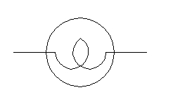
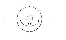
But then I ran across a handwritten sketch that I believe you drew up for this circuit. It has a 470 Ohm - 1 Watt resistor in the wire between the hot side of the starter contactor and the lamp. It also shows a 1N4001 protection diode in parallel with the lamp and ground. It isn't clear from your sketch (and my electrical symbols knowledge is limited) whether the lamp is incandescent or an LED. |
This is an incandescent lamp
[img]cid:7.1.0.9.0.20110218094700.01d98650(at)aeroelectric.com.0[/img]
This is an Light Emitting Diode
[img]cid:7.1.0.9.0.20110218094700.01d98650(at)aeroelectric.com.1[/img]
The resistor used with the LED warning circuit as
sketched serves a dual purpose. It protects the wire
that runs from starter to lamp by limiting the maximum
current that could flow in a faulted wire. At the same
time, it SETS the current intended to illuminate the
LED.
For an incandescent warning light, the resistor is
replaced with a fuse and the incandescent lamp is
substituted for the LED. No reverse current diode
is needed.
Bob . . .
| | - The Matronics AeroElectric-List Email Forum - | | | Use the List Feature Navigator to browse the many List utilities available such as the Email Subscriptions page, Archive Search & Download, 7-Day Browse, Chat, FAQ, Photoshare, and much more:
http://www.matronics.com/Navigator?AeroElectric-List |
|
| Description: |
|
| Filesize: |
8.64 KB |
| Viewed: |
1498 Time(s) |

|
| Description: |
|
| Filesize: |
8.05 KB |
| Viewed: |
1498 Time(s) |

|
|
|
| Back to top |
|
 |
nuckolls.bob(at)aeroelect
Guest
|
 Posted: Fri Feb 18, 2011 3:06 pm Post subject: "Starter Engaged" Warning Light Circuit Refresher Posted: Fri Feb 18, 2011 3:06 pm Post subject: "Starter Engaged" Warning Light Circuit Refresher |
 |
|
At 05:43 PM 2/18/2011, you wrote:
| Quote: | | Bob N., Is the drawing for this circuit in the Aeroelectric archives? I think I'd like to add it to my very bare bones system. |
http://aeroelectric.com/Pictures/Schematics/Starter_Engaged_Warning_Lt.pdf
| Quote: | Bob N.,
I'm putting a "starter engaged" warning light in my new IFR panel. I simply hooked the incandescent bulb from my B&C alternator "low voltage" warning light between a fused wire that runs from the hot side of the starter contactor and ground. (I now have the standby B&C alternator and will use its controller's "standby alternator on" light in lieu of the low voltage light on the primary alternator controller.)
But then I ran across a handwritten sketch that I believe you drew up for this circuit. It has a 470 Ohm - 1 Watt resistor in the wire between the hot side of the starter contactor and the lamp. It also shows a 1N4001 protection diode in parallel with the lamp and ground. It isn't clear from your sketch (and my electrical symbols knowledge is limited) whether the lamp is incandescent or an LED. |
This is an incandescent lamp
[img]cid:7.1.0.9.0.20110218170144.01fc2908(at)aeroelectric.com.2[/img]
This is an Light Emitting Diode
[img]cid:7.1.0.9.0.20110218170144.01fc2908(at)aeroelectric.com.3[/img]
The resistor used with the LED warning circuit as
sketched serves a dual purpose. It protects the wire
that runs from starter to lamp by limiting the maximum
current that could flow in a faulted wire. At the same
time, it SETS the current intended to illuminate the
LED.
For an incandescent warning light, the resistor is
replaced with a fuse and the incandescent lamp is
substituted for the LED. No reverse current diode
is needed.
Bob . . .
| | - The Matronics AeroElectric-List Email Forum - | | | Use the List Feature Navigator to browse the many List utilities available such as the Email Subscriptions page, Archive Search & Download, 7-Day Browse, Chat, FAQ, Photoshare, and much more:
http://www.matronics.com/Navigator?AeroElectric-List |
|
| Description: |
|
| Filesize: |
8.64 KB |
| Viewed: |
1488 Time(s) |

|
| Description: |
|
| Filesize: |
8.05 KB |
| Viewed: |
1488 Time(s) |

|
|
|
| Back to top |
|
 |
|
|
You cannot post new topics in this forum
You cannot reply to topics in this forum
You cannot edit your posts in this forum
You cannot delete your posts in this forum
You cannot vote in polls in this forum
You cannot attach files in this forum
You can download files in this forum
|
Powered by phpBB © 2001, 2005 phpBB Group
|


