 |
Matronics Email Lists
Web Forum Interface to the Matronics Email Lists
|
| View previous topic :: View next topic |
| Author |
Message |
Michael Wynn
Joined: 10 Jan 2006
Posts: 148
Location: San Ramon, CA
|
 Posted: Mon Jun 27, 2011 5:47 am Post subject: Mechanics of adding resistors Posted: Mon Jun 27, 2011 5:47 am Post subject: Mechanics of adding resistors |
 |
|
Hi all,


 I am wiring a Grand Rapids EIS 4000 into my RV 8.  The unit has a 4.8V  "exciter" circuit.  Two auxiliary inputs are for fuel tank sensors.  I  understand from the wiring diagram here


 http://f1.grp.yahoofs.com/v1/0H4ITpn8XkreroJCKrbKAiMAAupS245hbJv750-QGDWR_sM4xYTe_rS3WbvLLocO9yHTwpDwbZCoOirg3wW5zJBdnGsGgN0/File0002.pdf


 that I wire a 470 ohm resistor between the 4.8V exciter circuit and the  wire to the fuel tank sensor.  The other end of the fuel tank sensor goes  to ground.


 Since there are two circuits, one to each fuel tank, I had thought to  solder or crimp the two resistors to the exciter wire and then strip a half inch  of the wire from the EIS unit to the fuel sensor.  The ends of the  resistors would be soldered into the sensor wire and the joint covered in heat  shrink.


 I began to wonder how much heat would be generated and if I need to protect  this from other wires.  I wouldn't think there would be much heat since  there is little current in a sensor.


 Can anyone shed some light on the mechanics of how I should set this  up?


 Regards


 Michael Wynn

 RV 8 Wiring

 San Ramon, CA


  [quote][b]
| | - The Matronics AeroElectric-List Email Forum - | | | Use the List Feature Navigator to browse the many List utilities available such as the Email Subscriptions page, Archive Search & Download, 7-Day Browse, Chat, FAQ, Photoshare, and much more:
http://www.matronics.com/Navigator?AeroElectric-List |
|
_________________
Michael Wynn
RV 8
San Ramon, CA |
|
| Back to top |
|
 |
nuckolls.bob(at)aeroelect
Guest
|
| Posted: Mon Jun 27, 2011 6:44 am Post subject: Mechanics of adding resistors |
|
|
At 08:41 AM 6/27/2011, you wrote:
Hi all,
I am wiring a Grand Rapids EIS 4000 into my RV 8. The unit has a 4.8V "exciter" circuit. Two auxiliary inputs are for fuel tank sensors. I understand from the wiring diagram here
http://f1.grp.yahoofs.com/v1/0H4ITpn8XkreroJCKrbKAiMAAupS245hbJv750-QGDWR_sM4xYTe_rS3WbvLLocO9yHTwpDwbZCoOirg3wW5zJBdnGsGgN0/File0002.pdf
I tried to open that link but was not successful . . .
that I wire a 470 ohm resistor between the 4.8V exciter circuit and the wire to the fuel tank sensor. The other end of the fuel tank sensor goes to ground.
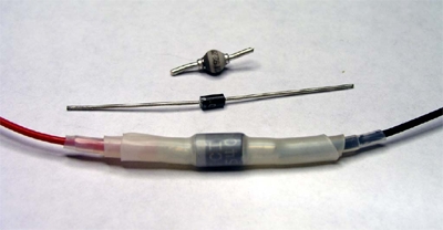
Since there are two circuits, one to each fuel tank, I had thought to solder or crimp the two resistors to the exciter wire and then strip a half inch of the wire from the EIS unit to the fuel sensor. The ends of the resistors would be soldered into the sensor wire and the joint covered in heat shrink.
Like this?
[img]cid:7.1.0.9.0.20110627093341.02040838(at)aeroelectric.com.0[/img]
See: http://www.aeroelectric.com/articles/Homeless/Homeless_Components.htm
I began to wonder how much heat would be generated and if I need to protect this from other wires. I wouldn't think there would be much heat since there is little current in a sensor.
Correct. If there's a reason for selecting larger
than necessary for electrical performance, it's for
mechanical robustness. Consider 1/2 watt resistors
for this task.
Bob . . .
| | - The Matronics AeroElectric-List Email Forum - | | | Use the List Feature Navigator to browse the many List utilities available such as the Email Subscriptions page, Archive Search & Download, 7-Day Browse, Chat, FAQ, Photoshare, and much more:
http://www.matronics.com/Navigator?AeroElectric-List |
|
| Description: |
|
| Filesize: |
49.21 KB |
| Viewed: |
2671 Time(s) |
|
|
|
| Back to top |
|
|
rv8iator(at)gmail.com
Guest
|
| Posted: Mon Jun 27, 2011 7:04 am Post subject: Mechanics of adding resistors |
|
|
Hello Michael,
Just finished a similar install on a Dynon D180 and Rotax with multiple resistors for current loop sensors. Choose a point in-line for the resistors that you can mechanically support the wire bundle. Trim the resistor leads to about 1/2" slip multiple layers of heat shrink tubing onto the wires before assembly if unable to add heatshrink post assembly. I soldered all connections. Heatshrink tubing over each resistor, then bundle and larger heatshrink tubing. Be sure to extend the heatshrink tubing 1" or further beyond the connection for mechanical support. The current the resistors is limiting is in the 10s of milliamps range and thus almost no power (heat) is dissapated.
Chris Stone
RV-8
Oregon
On Mon, Jun 27, 2011 at 6:41 AM, <MLWynn(at)aol.com (MLWynn(at)aol.com)> wrote:
[quote]
Hi all,
I am wiring a Grand Rapids EIS 4000 into my RV 8. The unit has a 4.8V "exciter" circuit. Two auxiliary inputs are for fuel tank sensors. I understand from the wiring diagram here
http://f1.grp.yahoofs.com/v1/0H4ITpn8XkreroJCKrbKAiMAAupS245hbJv750-QGDWR_sM4xYTe_rS3WbvLLocO9yHTwpDwbZCoOirg3wW5zJBdnGsGgN0/File0002.pdf
that I wire a 470 ohm resistor between the 4.8V exciter circuit and the wire to the fuel tank sensor. The other end of the fuel tank sensor goes to ground.
Since there are two circuits, one to each fuel tank, I had thought to solder or crimp the two resistors to the exciter wire and then strip a half inch of the wire from the EIS unit to the fuel sensor. The ends of the resistors would be soldered into the sensor wire and the joint covered in heat shrink.
I began to wonder how much heat would be generated and if I need to protect this from other wires. I wouldn't think there would be much heat since there is little current in a sensor.
Can anyone shed some light on the mechanics of how I should set this up?
Regards
Michael Wynn
RV 8 Wiring
San Ramon, CA
| Quote: |
ist" target="_blank">http://www.matronics.com/Navigator?AeroElectric-List
tp://forums.matronics.com
_blank">http://www.matronics.com/contribution
|
[b]
| | - The Matronics AeroElectric-List Email Forum - | | | Use the List Feature Navigator to browse the many List utilities available such as the Email Subscriptions page, Archive Search & Download, 7-Day Browse, Chat, FAQ, Photoshare, and much more:
http://www.matronics.com/Navigator?AeroElectric-List |
|
|
|
| Back to top |
|
|
Michael Wynn
Joined: 10 Jan 2006
Posts: 148
Location: San Ramon, CA
|
| Posted: Mon Jun 27, 2011 1:25 pm Post subject: Mechanics of adding resistors |
|
|
Thanks, Bob
You are right on top of everything, as usual.
Michael Wynn
Do Not Archive
In a message dated 6/27/2011 7:45:17 A.M. Pacific Daylight Time, nuckolls.bob(at)aeroelectric.com writes:
| Quote: | At 08:41 AM 6/27/2011, you wrote:
Hi all,
I am wiring a Grand Rapids EIS 4000 into my RV 8. The unit has a 4.8V "exciter" circuit. Two auxiliary inputs are for fuel tank sensors. I understand from the wiring diagram here
http://f1.grp.yahoofs.com/v1/0H4ITpn8XkreroJCKrbKAiMAAupS245hbJv750-QGDWR_sM4xYTe_rS3WbvLLocO9yHTwpDwbZCoOirg3wW5zJBdnGsGgN0/File0002.pdf
I tried to open that link but was not successful . . .
that I wire a 470 ohm resistor between the 4.8V exciter circuit and the wire to the fuel tank sensor. The other end of the fuel tank sensor goes to ground.
Since there are two circuits, one to each fuel tank, I had thought to solder or crimp the two resistors to the exciter wire and then strip a half inch of the wire from the EIS unit to the fuel sensor. The ends of the resistors would be soldered into the sensor wire and the joint covered in heat shrink.
Like this?
See: http://www.aeroelectric.com/articles/Homeless/Homeless_Components.htm
I began to wonder how much heat would be generated and if I need to protect this from other wires. I wouldn't think there would be much heat since there is little current in a sensor.
Correct. If there's a reason for selecting larger
than necessary for electrical performance, it's for
mechanical robustness. Consider 1/2 watt resistors
for this task.
Bob . . . |
| | - The Matronics AeroElectric-List Email Forum - | | | Use the List Feature Navigator to browse the many List utilities available such as the Email Subscriptions page, Archive Search & Download, 7-Day Browse, Chat, FAQ, Photoshare, and much more:
http://www.matronics.com/Navigator?AeroElectric-List |
|
| Description: |
|
| Filesize: |
49.21 KB |
| Viewed: |
2660 Time(s) |

|
_________________
Michael Wynn
RV 8
San Ramon, CA |
|
| Back to top |
|
|
nuckolls.bob(at)aeroelect
Guest
|
| Posted: Mon Jun 27, 2011 3:17 pm Post subject: Mechanics of adding resistors |
|
|
At 04:21 PM 6/27/2011, you wrote:
| Quote: | Thanks, Bob
You are right on top of everything, as usual.
|
It's worthy of note that others had the same
advice. If more than one individual has been-there-
done-that, it MUST be a practical recipe for
success.
Bob . . . [quote][b]
| | - The Matronics AeroElectric-List Email Forum - | | | Use the List Feature Navigator to browse the many List utilities available such as the Email Subscriptions page, Archive Search & Download, 7-Day Browse, Chat, FAQ, Photoshare, and much more:
http://www.matronics.com/Navigator?AeroElectric-List |
|
|
|
| Back to top |
|
|
|
|
You cannot post new topics in this forum
You cannot reply to topics in this forum
You cannot edit your posts in this forum
You cannot delete your posts in this forum
You cannot vote in polls in this forum
You cannot attach files in this forum
You can download files in this forum
|
Powered by phpBB © 2001, 2005 phpBB Group
|

