 |
Matronics Email Lists
Web Forum Interface to the Matronics Email Lists
|
| View previous topic :: View next topic |
| Author |
Message |
teamgrumman(at)yahoo.com
Guest
|
 Posted: Wed Dec 07, 2011 1:18 pm Post subject: Grumman Airfoil Posted: Wed Dec 07, 2011 1:18 pm Post subject: Grumman Airfoil |
 |
|
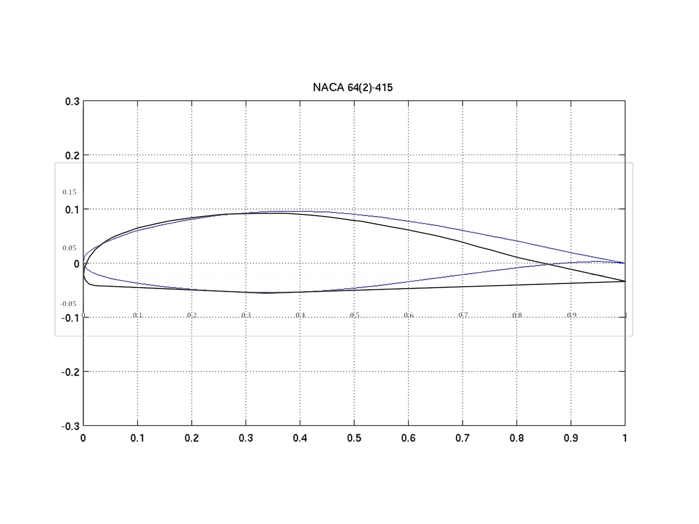
Attach 1:  Grumman airfoil over layed on 64-415 at presumed zero line.

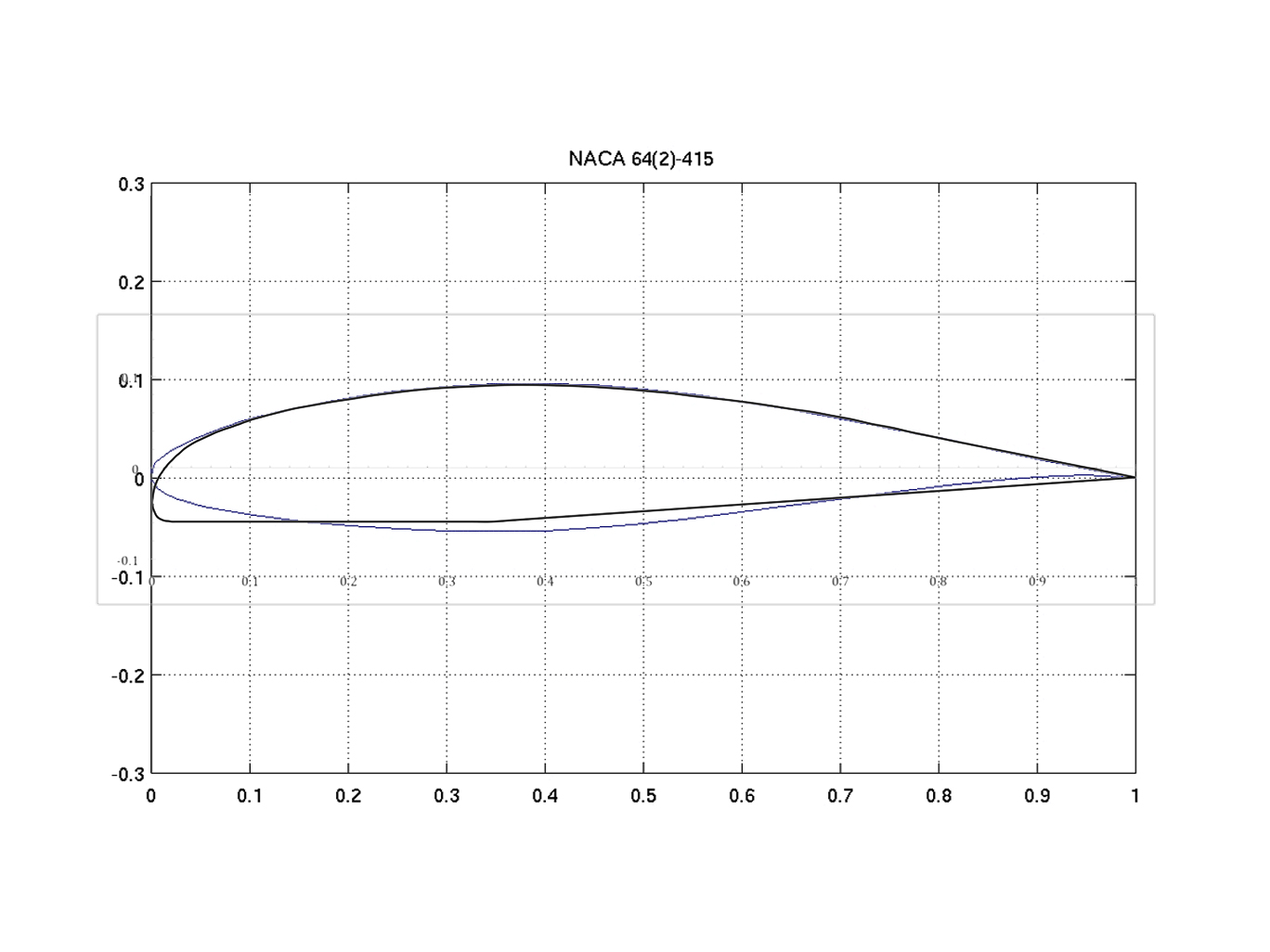
Attach 2:  Grumman airfoil over layed on 64-415 at best fit.

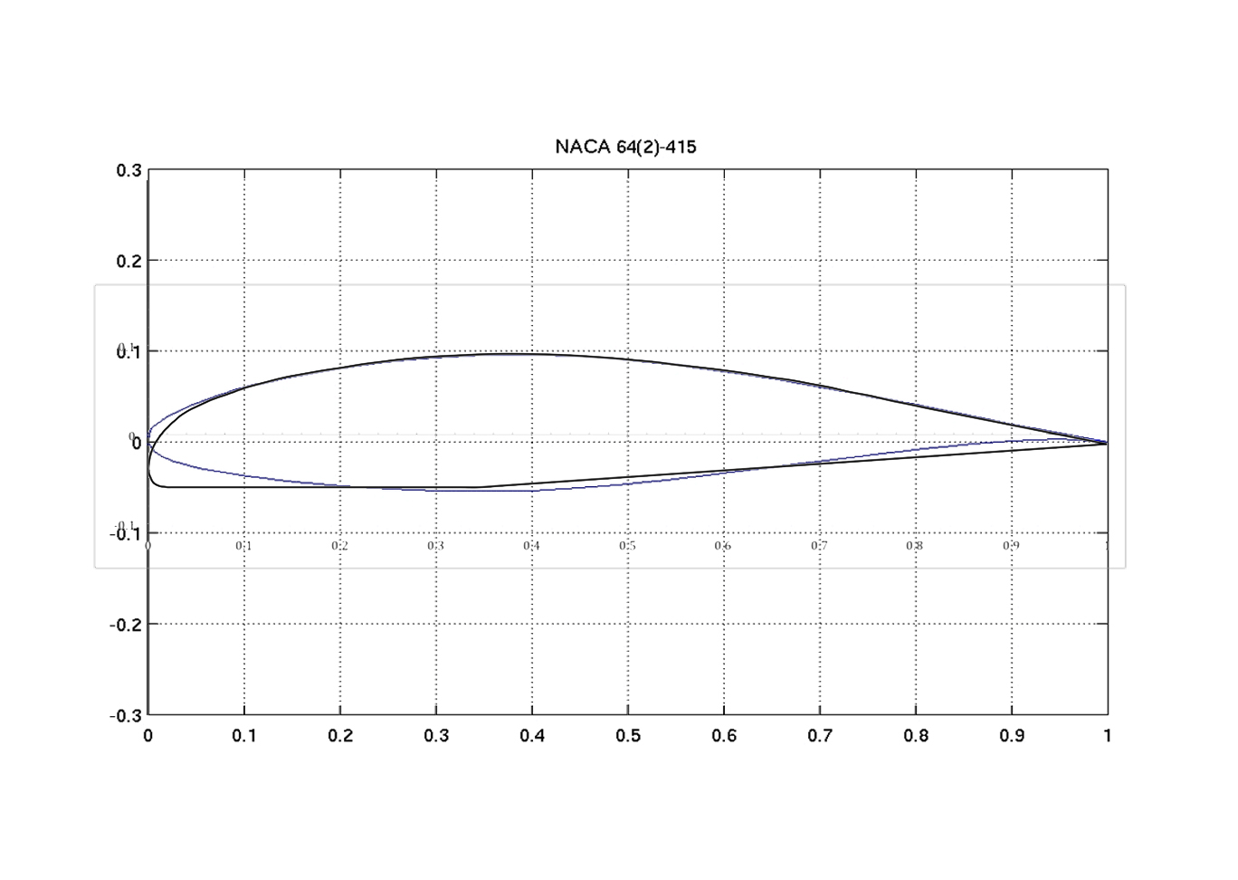
Attach 3:  Grumman airfoil over layed on 63-415 at presumed zero line. �(a thinner airfoil)

Bottom line is

1) The airfoil is slightly thinner than what a computed 64-415 would be.

2) The forward flat portion of the wing is the reference angle.
| | - The Matronics TeamGrumman-List Email Forum - | | | Use the List Feature Navigator to browse the many List utilities available such as the Email Subscriptions page, Archive Search & Download, 7-Day Browse, Chat, FAQ, Photoshare, and much more:
http://www.matronics.com/Navigator?TeamGrumman-List |
|
| Description: |
|
| Filesize: |
263.96 KB |
| Viewed: |
8351 Time(s) |

|
| Description: |
|
| Filesize: |
257.79 KB |
| Viewed: |
8351 Time(s) |

|
| Description: |
|
| Filesize: |
254.34 KB |
| Viewed: |
8351 Time(s) |

|
|
|
| Back to top |
|
 |
n76lima(at)mindspring.com
Guest
|
 Posted: Wed Dec 07, 2011 1:59 pm Post subject: Grumman Airfoil Posted: Wed Dec 07, 2011 1:59 pm Post subject: Grumman Airfoil |
 |
|
| Quote: | Attach 1: Grumman airfoil over layed on 64-415 at presumed zero line.
Attach 2: Grumman airfoil over layed on 64-415 at best fit.
Attach 3: Grumman airfoil over layed on 63-415 at presumed zero
line. (a thinner airfoil)
Bottom line is
1) The airfoil is slightly thinner than what a computed 64-415 would be.
2) The forward flat portion of the wing is the reference angle.
|
The filled in trailing edge cusp on the Grumman airfoil vs. the NACA
ones is common, to reduce the loading on the controls. Basically a straight
| Quote: | No virus found in this message.
Checked by AVG - <http://www.avg.com>www.avg.com
|
| | - The Matronics TeamGrumman-List Email Forum - | | | Use the List Feature Navigator to browse the many List utilities available such as the Email Subscriptions page, Archive Search & Download, 7-Day Browse, Chat, FAQ, Photoshare, and much more:
http://www.matronics.com/Navigator?TeamGrumman-List |
|
|
|
| Back to top |
|
 |
n76lima(at)mindspring.com
Guest
|
 Posted: Wed Dec 07, 2011 2:03 pm Post subject: Grumman Airfoil Posted: Wed Dec 07, 2011 2:03 pm Post subject: Grumman Airfoil |
 |
|
| Quote: | Attach 1: Grumman airfoil over layed on 64-415 at presumed zero line.
Attach 2: Grumman airfoil over layed on 64-415 at best fit.
Attach 3: Grumman airfoil over layed on 63-415 at presumed zero
line. (a thinner airfoil)
Bottom line is
1) The airfoil is slightly thinner than what a computed 64-415 would be.
2) The forward flat portion of the wing is the reference angle.
|
The filled in trailing edge cusp on the Grumman airfoil vs. the NACA
ones is common, to reduce the loading on the controls. Basically a
straight line is drawn from the pivot point of the aileron (or flap)
back to the trailing edge and the cusp is removed. You'll see this
on nearly every production aircraft.
Looks like they might have altered the point of max thickness to
accommodate the spar tube, so that its center is near the 25% MAC
point, where torque is usually summed for calculations on the torsion
box for the built up spar designs.
Thanks for the excellent plots Gary.
--Bob Steward
| | - The Matronics TeamGrumman-List Email Forum - | | | Use the List Feature Navigator to browse the many List utilities available such as the Email Subscriptions page, Archive Search & Download, 7-Day Browse, Chat, FAQ, Photoshare, and much more:
http://www.matronics.com/Navigator?TeamGrumman-List |
|
|
|
| Back to top |
|
 |
ronmillmancpa(at)msn.com
Guest
|
 Posted: Wed Dec 07, 2011 3:32 pm Post subject: Grumman Airfoil Posted: Wed Dec 07, 2011 3:32 pm Post subject: Grumman Airfoil |
 |
|
Thanks for keeping us up to date.
Ron Millman� N81218����� 1977 AA5B
Ronald D. Millman, C.P.A.�� "The greatest good you can do for another is not just to share your riches but to reveal to him his own" � Benjamin Disraeli.����� � Hey.........., that's what a CPA does!
�
�� [img][/img]
�
�
�
| Quote: | Date: Wed, 7 Dec 2011 16:01:24 -0600
To: teamgrumman-list(at)matronics.com
From: n76lima(at)mindspring.com
Subject: Re: Grumman Airfoil
--> TeamGrumman-List message posted by: Bob Steward <n76lima(at)mindspring.com>
>Attach 1: Grumman airfoil over layed on 64-415 at presumed zero line.
>Attach 2: Grumman airfoil over layed on 64-415 at best fit.
>Attach 3: Grumman airfoil over layed on 63-415 at presumed zero
>line. (a thinner airfoil)
>
>Bottom line is
>1) The airfoil is slightly thinner than what a computed 64-415 would be.
>2) The forward flat portion of the wing is the reference angle.
The filled in trailing edge cusp on the Grumman airfoil vs. the NACA
ones is common, to reduce the loading on the controls. Basically a
straight line is drawn from the pivot point of the aileron (or flap)
back to the trailing edge and the cusp is removed. You'll see this
on nearly every production aircraft.
Looks like they might have altered the point of max thickness to
accommodate the spar tube, so that its center is near the 25% MAC
point, where torque is usually summed for calculations on the torsion
box for the built up spar designs.
Thanks for the excellent plots Gary.
--Bob Steward
>-= --> http://www.matronics.com/Navigator?TeamGrumman-List
|
>=
[quote][b]
| | - The Matronics TeamGrumman-List Email Forum - | | | Use the List Feature Navigator to browse the many List utilities available such as the Email Subscriptions page, Archive Search & Download, 7-Day Browse, Chat, FAQ, Photoshare, and much more:
http://www.matronics.com/Navigator?TeamGrumman-List |
|
|
|
| Back to top |
|
 |
teamgrumman(at)yahoo.com
Guest
|
 Posted: Wed Dec 07, 2011 8:50 pm Post subject: Grumman Airfoil Posted: Wed Dec 07, 2011 8:50 pm Post subject: Grumman Airfoil |
 |
|
Sometimes I think I take for granted everyone thinks the way I write. It would sure be easier if you all did.
1) Regarding the cusp on the 64-415 airfoil. I can come pretty close to approximating that if I deflect the flap 1/4 to 1/2 inch. Not a big player in this discussion.
2) The modified 64-415 airfoil, to make it thinner, is to get a better fit to the Grumman airfoil.
• The 15, in -415, means the thickness of the airfoil should be 15% at the minimum pressure location.
• In the case of the Grumman wing, it's closer to 14.88%. So, I only needed to thin the 64-415 wing a schosh to make it fit better.
3) The spar is placed at the 34.55% MAC. That is the location of minimum pressure.
• The shorter AA1 wing was closer to 40% given a 64-415 wing.
� • Ideally, something like the 65-415 Comanche wing with the minimum pressure at 50% would make a faster wing.
• The P-51 uses a 66-415 wing; i.e., minimum pressure is at 60% of the chord.
You're more than welcome for the plots, Bob. I spent 3 hours a day for 3 days measuring and remeasuring and then fine tuning the plots to eliminate wiggles.
Next step is to find a wing (with data) that is close to the Grumman wing. So far, I've compared 671 airfoils to the Grumman airfoil. Some fit OK. Others are not even close.
If I had unlimited cash flow, I'd hire the guys who built the last batch of AG5B wings to build me a set with the original airfoil.
Gary
From: Bob Steward <n76lima(at)mindspring.com>
To: teamgrumman-list(at)matronics.com
Sent: Wednesday, December 7, 2011 2:01 PM
Subject: Re: Grumman Airfoil
--> TeamGrumman-List message posted by: Bob Steward <n76lima(at)mindspring.com (n76lima(at)mindspring.com)>
| Quote: | Attach 1:� Grumman airfoil over layed on 64-415 at presumed zero line.
Attach 2: Grumman airfoil over layed on 64-415 at best fit.
Attach 3: Grumman airfoil over layed on 63-415 at presumed zero line. (a thinner airfoil)
Bottom line is
1) The airfoil is slightly thinner than what a computed 64-415 would be.
2) The forward flat portion of the wing is the reference angle.
|
The filled in trailing edge cusp on the Grumman airfoil vs. the NACA ones is common, to reduce the loading on the controls. Basically a straight line is drawn from the pivot point of the aileron (or flap) back to the trailing edge and the cusp is removed. You'll see this on nearly every production aircraft.
Looks like they might have altered the point of max thickness to accommodate the spar tube, so that its center is near the 25% MAC point, where torque is usually summed for calculations on the torsion box for the built up spar designs.
Thanks for the excellent plots Gary.http://www.ma======================
[quote][b]
| | - The Matronics TeamGrumman-List Email Forum - | | | Use the List Feature Navigator to browse the many List utilities available such as the Email Subscriptions page, Archive Search & Download, 7-Day Browse, Chat, FAQ, Photoshare, and much more:
http://www.matronics.com/Navigator?TeamGrumman-List |
|
|
|
| Back to top |
|
 |
|
|
You cannot post new topics in this forum
You cannot reply to topics in this forum
You cannot edit your posts in this forum
You cannot delete your posts in this forum
You cannot vote in polls in this forum
You cannot attach files in this forum
You can download files in this forum
|
Powered by phpBB © 2001, 2005 phpBB Group
|


