nuckolls.bob(at)aeroelect
Guest
|
 Posted: Fri Dec 16, 2011 7:11 am Post subject: Use of non-aviation Ford-style regulators Posted: Fri Dec 16, 2011 7:11 am Post subject: Use of non-aviation Ford-style regulators |
 |
|
Paul Millner wrote:


 Note that it can be dangerous to use non-aviation Ford-type regulators in our airplanes. When the alternator half of the master switch is turned off, the regulator will allow the alternator to go into a voltage runaway mode, and that overvoltage will not be controlled by your overvoltage relay (since the field current is flowing via a separate path, directly from the alternator). The overvoltage condition can cook your avionics and battery.


 Even if you don't turn off the alternator half of the master switch, if your separate overvoltage relay trip for any reason with such a regulator installed, that, ironically, will trigger the voltage runaway scenario.


 Paul


 At 07:02 PM 12/15/2011, you wrote:

 --> AeroElectric-List message posted by: David <ainut(at)knology.net>


 Uh oh.  What's the protection for this?  I'm using not a Ford, but a smaller, denser, lighter Japanese alternator with same output.


 David Merchant


     Man! I've not had occasion to lift the lid on this

     pot of stew since I owned the Benton Airpark (1K1)

     22 years ago.


     Paul's admonition arises from the fact that SOME

     solid state replacements for the original Ford

     electromechanical regulators do not conform to the

     form, fit and function of those regulators. As installed

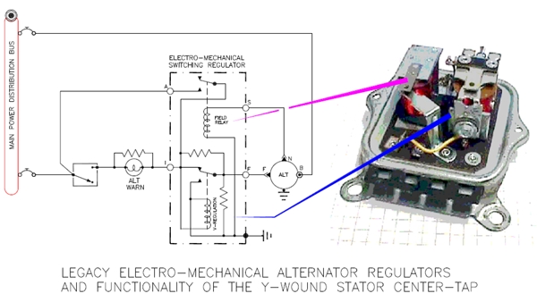
     first on automobiles the Ford style regulator was

     configured thusly:


 [img]cid:.0[/img]

    The regulator contained two "relay" like devices wherein

    one relay was the voltage regulator and the second was

    used as an ON-OFF control of field excitation. The

    field relay sensed a DC voltage on the alternator's

    "N" terminal (y-wound stator center tap) and would

    automatically excite an alternator as soon as the

    engine was started and the alternator was demonstrated

    to be in motion. This all happened through a tiny

    excitation current that would flow through the

    alternator warning light bulb into the regulator's

    "I" or indicator terminal.


    Failure of this light bulb led to a lot of regulators

    and alternators being swapped out as mechanics who

    did not understand the system tried to get their

    customer's car back on the road. Later systems

    added a resistor across the lamp to make sure that

    the alternator would still come on line even if the

    bulb were burned out. This is the root-system from

    which Cessna's alternators evolved.


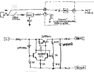
    Cessna chose to run their field supply voltage right

    into the "A" terminal and control the field supply

    relay directly with alternator field switch controlling

    the "S" terminal. In later years, the OV protection

    module (first proposed by yours truly) was inserted

    between the alternator field switch and the "S" terminal.


     [img]cid:.1[/img]


    So much for the history. In later years, solid state

    replacements with the same A, S, I and F terminal

    markings were crafted where the S-terminal was no

    longer used for field control but for BUS VOLTAGE

    SENSING. When one drops one of these regulators into

    an automobile, the system still performs in a useful

    manner. When dropped into a Cessna, opening the field

    control side of the split master switch deprived the

    regulator of control information causing the alternator

    to full-field . . . i.e. OV runaway.


    I'm not sure that ALL solid state drop-ins for a

    Ford regulator behave in this manner . . . but some

    do. Been there, done that on one of my rental fleet

    airplanes.  But if "Ford-style" regulators are wired

    per recommendations in the Z-figures (A and S terminals

    tied together) there is no risk for experiencing the

    design induced runaway condition.


   Bob . . .
| | - The Matronics AeroElectric-List Email Forum - | | | Use the List Feature Navigator to browse the many List utilities available such as the Email Subscriptions page, Archive Search & Download, 7-Day Browse, Chat, FAQ, Photoshare, and much more:
http://www.matronics.com/Navigator?AeroElectric-List |
|
| Description: |
|
| Filesize: |
100.93 KB |
| Viewed: |
863 Time(s) |

|
| Description: |
|
| Filesize: |
53.56 KB |
| Viewed: |
863 Time(s) |

|
|
|


