 |
Matronics Email Lists
Web Forum Interface to the Matronics Email Lists
|
| View previous topic :: View next topic |
| Author |
Message |
nuckolls.bob(at)aeroelect
Guest
|
 Posted: Fri Feb 24, 2012 9:38 am Post subject: Dipole antenna fabrication Posted: Fri Feb 24, 2012 9:38 am Post subject: Dipole antenna fabrication |
 |
|
At 09:39 AM 2/24/2012, you wrote:


Etienne drew a T-antenna on his discussion of the servo problem. This

incluced stripping back the insulation on a coax, separating the

shield and core, and stretching out each to form a Tee.


Clever. Actually too-clever-by-half. Would that it could be so easy!

The problem lies in the termination, since the core and shield do not

share the signal. In fact neither the core nor the shield even CARRY

the signal.


See: periheliondesign.com/downloads/Dabbling%20with%20electricity.pdf


Then grab your SWR meter and Google any of the ham radio sites and

see how to design a T-antenna.


Might it work the way Etienne shows? A little probably, but let's do it right.

   Can you cite a website specific to the

   fabrication of VHF dipoles fed with

   coax?


   Bob . . .
| | - The Matronics AeroElectric-List Email Forum - | | | Use the List Feature Navigator to browse the many List utilities available such as the Email Subscriptions page, Archive Search & Download, 7-Day Browse, Chat, FAQ, Photoshare, and much more:
http://www.matronics.com/Navigator?AeroElectric-List |
|
|
|
| Back to top |
|
 |
Eric M. Jones
Joined: 10 Jan 2006
Posts: 565
Location: Massachusetts
|
| Posted: Fri Feb 24, 2012 10:44 am Post subject: Re: Dipole antenna fabrication |
|
|
Bob,


I see that there are thousands of sites when you Google them. But here a general purpose one that will get one started and discusses the issues (sorry for all the equations...):

http://en.wikipedia.org/wiki/Dipole_antenna


But Bob, in your vast experience, have you seen many dipoles per Etienne's drawing?
| | - The Matronics AeroElectric-List Email Forum - | | | Use the List Feature Navigator to browse the many List utilities available such as the Email Subscriptions page, Archive Search & Download, 7-Day Browse, Chat, FAQ, Photoshare, and much more:
http://www.matronics.com/Navigator?AeroElectric-List |
|
_________________
Eric M. Jones
www.PerihelionDesign.com
113 Brentwood Drive
Southbridge, MA 01550
(508) 764-2072
emjones(at)charter.net |
|
| Back to top |
|
|
deej(at)deej.net
Guest
|
| Posted: Fri Feb 24, 2012 10:57 am Post subject: Dipole antenna fabrication |
|
|
On 2/24/2012 1:44 PM, Eric M. Jones wrote:
I'm not Bob, but his diagram looks like the one at the top right of
the page on that link you sent, and looks normal to me. I've made many
of these types of antennas for ham equipment when a quick-n-dirty setup
was needed. In fact, I just made one a couple of weeks ago for an APRS
setup. They tend to work okay. Not great, just okay. Much better than
the flexible antennas that come on a handheld radio.
What specifically are you seeing wrong with it?
-Dj
--
Dj Merrill - N1JOV
Sportsman 2+2 Builder #7118 N421DJ - http://deej.net/sportsman/
Glastar Flyer N866RH - http://deej.net/glastar/
| | - The Matronics AeroElectric-List Email Forum - | | | Use the List Feature Navigator to browse the many List utilities available such as the Email Subscriptions page, Archive Search & Download, 7-Day Browse, Chat, FAQ, Photoshare, and much more:
http://www.matronics.com/Navigator?AeroElectric-List |
|
|
|
| Back to top |
|
|
nuckolls.bob(at)aeroelect
Guest
|
| Posted: Fri Feb 24, 2012 7:14 pm Post subject: Dipole antenna fabrication |
|
|
At 12:44 PM 2/24/2012, you wrote:
--> AeroElectric-List message posted by: "Eric M. Jones" <emjones(at)charter.net>
Bob,
I see that there are thousands of sites when you Google them. But here a general purpose one that will get one started and discusses the issues (sorry for all the equations...):
http://en.wikipedia.org/wiki/Dipole_antenna
But Bob, in your vast experience, have you seen many dipoles per Etienne's drawing?
Oh yeah . . . tens of thousands. For many years during
the vacuum tube days of aviation radio, tens of thousands
of single engine Cessna's went out the door with VOR whiskers
in the vertical fin cap that were nothing more sophisticated
than Etienne's coax fed dipole.
Granted, the whiskers were stuck out in the breeze and
assembled to the end of the coax but electrically, no
different. I think we had a brief romance with adding
BALUNS to these antennas. But without spending money
to do really scientific tests on the antenna range,
we generally relied on the anecdotal observations of
production and flight test pilots. Cessna was putting
10,000 airplanes a year out the door on 5 production
lines.
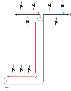
Some years later, Jim Weir suggested adding ferrite
toroidal cores the coax right at the junction with
the antenna. The idea was to reduce coax radiation
depicted in the Wikipedia article
[img]cid:.0[/img]
. . . radiation caused by less than ideal termination
of the feedline. I tested this work-around in the EMC
lab at HBC about 15 years ago and found that an array
of 10 cores had no appreciable effect on these stray
shield currents.
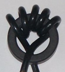
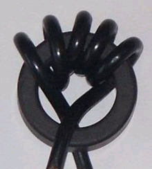
Years later I suffered this "hot-d(at)#n" moment. I saw
an antenna product wherein the string of ferrites was
replace with a single ferrite core. The coax was
wound through it several times.
[img]cid:.1[/img]
But of course! Inductance in a single magnetic circuit
varies with the SQUARE of turns. The picture seen here
has 6 passes of the coax through the core. It is the
electrical equivalent of 36 single cores. Now, having
'discovered' that, it would still be interesting to
go to the lab and see how effective it is.
Had we possessed the knowledge and materials to
duplicate this technique on a 1967 Cessna 172, I'll
bet the pilots would have continued to report "no
observable difference" in hearing the VORs.
Of course, transmit is a different story. Energy
levels are perhaps 130db higher (10 trillion
stronger). The effects of poorly terminated coax
don't have much to do with transmit/receive
performance but MIGHT have an impact on how
much energy is coupled into unwanted systems
radiated from coax feed lines bundled in with
other wires.
But then, the potential for interfering signals
radiated DIRECTLY from the antenna is already
very high on a small airplane. If it's a plastic
airplane, it's worse yet. And those 'el cheeso
vertical dipoles tend to be really popular for
installation in vertical fins of plastic airplanes.
Admittedly, these antennas are not the best we
know how to do . . . but they are easy to implement.
They pose some risks for EMC issues. But the
relative success with these installations suggests
that the ship's 'other' appliances are reasonably
designed immunity to strong external fields.
The genesis thread discovered that making the servo
more robust to the strong RFI environment was
a good solution. But given that it's a plastic
airplane, it's not clear that refining the
antenna's feed point design would have made any
difference at all.
Bob . . .
| | - The Matronics AeroElectric-List Email Forum - | | | Use the List Feature Navigator to browse the many List utilities available such as the Email Subscriptions page, Archive Search & Download, 7-Day Browse, Chat, FAQ, Photoshare, and much more:
http://www.matronics.com/Navigator?AeroElectric-List |
|
| Description: |
|
| Filesize: |
19.96 KB |
| Viewed: |
15399 Time(s) |
|
| Description: |
|
| Filesize: |
22.19 KB |
| Viewed: |
15399 Time(s) |
|
|
|
| Back to top |
|
|
Eric M. Jones
Joined: 10 Jan 2006
Posts: 565
Location: Massachusetts
|
| Posted: Sun Feb 26, 2012 9:41 am Post subject: Re: Dipole antenna fabrication |
|
|
The Wiki site shows a simple dipole and the caption says:


"A schematic of a half-wave dipole antenna connected to an unbalanced coaxial cable. Better practice is to connect the balanced dipole to the unbalanced line with a balun."


I've been thinking of putting aluminum foil on the TV rabbit ears....


Proper termination is the key to antenna efficiency. If Cessna didn't do it, that doesn't mean the homebuilder shouldn't do it right.


Bob et al. having flown extensively in the Western states and Mexico, I have plently of experience with being a zillion miles from a station. At those times I start to think that having a good radio and good antennas is a wise and cost effective thing to do. But do what you want.
| | - The Matronics AeroElectric-List Email Forum - | | | Use the List Feature Navigator to browse the many List utilities available such as the Email Subscriptions page, Archive Search & Download, 7-Day Browse, Chat, FAQ, Photoshare, and much more:
http://www.matronics.com/Navigator?AeroElectric-List |
|
_________________
Eric M. Jones
www.PerihelionDesign.com
113 Brentwood Drive
Southbridge, MA 01550
(508) 764-2072
emjones(at)charter.net |
|
| Back to top |
|
|
rhdudley1(at)bellsouth.ne
Guest
|
| Posted: Sun Feb 26, 2012 10:38 am Post subject: Dipole antenna fabrication |
|
|
A wise (and practical) person once said:
"Perfection is the enemy of good enough."
Anymouse
RHDudley
On 2/26/2012 12:41 PM, Eric M. Jones wrote:
| Quote: |
The Wiki site shows a simple dipole and the caption says:
"A schematic of a half-wave dipole antenna connected to an unbalanced coaxial cable. Better practice is to connect the balanced dipole to the unbalanced line with a balun."
I've been thinking of putting aluminum foil on the TV rabbit ears....
Proper termination is the key to antenna efficiency. If Cessna didn't do it, that doesn't mean the homebuilder shouldn't do it right.
Bob et al. having flown extensively in the Western states and Mexico, I have plently of experience with being a zillion miles from a station. At those times I start to think that having a good radio and good antennas is a wise and cost effective thing to do. But do what you want.
--------
Eric M. Jones
www.PerihelionDesign.com
113 Brentwood Drive
Southbridge, MA 01550
(508) 764-2072
emjones(at)charter.net
Read this topic online here:
http://forums.matronics.com/viewtopic.php?p=367293#367293
|
| | - The Matronics AeroElectric-List Email Forum - | | | Use the List Feature Navigator to browse the many List utilities available such as the Email Subscriptions page, Archive Search & Download, 7-Day Browse, Chat, FAQ, Photoshare, and much more:
http://www.matronics.com/Navigator?AeroElectric-List |
|
|
|
| Back to top |
|
|
Eric M. Jones
Joined: 10 Jan 2006
Posts: 565
Location: Massachusetts
|
| Posted: Sun Feb 26, 2012 11:28 am Post subject: Re: Dipole antenna fabrication |
|
|
A good job is sufficient. We disagree on what constitutes a good job.
| | - The Matronics AeroElectric-List Email Forum - | | | Use the List Feature Navigator to browse the many List utilities available such as the Email Subscriptions page, Archive Search & Download, 7-Day Browse, Chat, FAQ, Photoshare, and much more:
http://www.matronics.com/Navigator?AeroElectric-List |
|
_________________
Eric M. Jones
www.PerihelionDesign.com
113 Brentwood Drive
Southbridge, MA 01550
(508) 764-2072
emjones(at)charter.net |
|
| Back to top |
|
|
deej(at)deej.net
Guest
|
| Posted: Sun Feb 26, 2012 12:13 pm Post subject: Dipole antenna fabrication |
|
|
On 2/26/2012 2:28 PM, Eric M. Jones wrote:
| Quote: |
A good job is sufficient. We disagree on what constitutes a good job.
|
Having made and used at least a few dozen of these types of
antennas, I can say they generally do perform a "good job". They
perform far better than a handheld antenna, and perhaps not as good as
some other types of antennas, but overall they are okay, and of course,
cheap to make!  Comparing $$ spent to value received they rank very Comparing $$ spent to value received they rank very
high.
-Dj
--
Dj Merrill - N1JOV
Sportsman 2+2 Builder #7118 N421DJ - http://deej.net/sportsman/
Glastar Flyer N866RH - http://deej.net/glastar/
| | - The Matronics AeroElectric-List Email Forum - | | | Use the List Feature Navigator to browse the many List utilities available such as the Email Subscriptions page, Archive Search & Download, 7-Day Browse, Chat, FAQ, Photoshare, and much more:
http://www.matronics.com/Navigator?AeroElectric-List |
|
|
|
| Back to top |
|
|
nuckolls.bob(at)aeroelect
Guest
|
| Posted: Sun Feb 26, 2012 8:38 pm Post subject: Dipole antenna fabrication |
|
|
At 11:41 AM 2/26/2012, you wrote:


The Wiki site shows a simple dipole and the caption says:


"A schematic of a half-wave dipole antenna connected to an unbalanced

coaxial cable. Better practice is to connect the balanced dipole to

the unbalanced line with a balun."


     . . . and I published instructions for adding this

     feature to a coax fed dipole at


http://aeroelectric.com/articles/BALUN/Balun_Fabrication.html


     . . . the same technique could be applied to a comm

    dipole.


I've been thinking of putting aluminum foil on the TV rabbit ears....


   Which will lower the resonant frequency of the antenna

   and perhaps lower the Q . . . wider bandwidth. But

   no benefit for relative efficiency compared to an "ideal"

   dipole at the same frequency.

Proper termination is the key to antenna efficiency. If Cessna didn't

do it, that doesn't mean the homebuilder shouldn't do it right.


   I can assure you that Dr. Wood read the same books

   we've all read about antennas with professional

   attendance to "better practice." The point I endeavored to

   make was that after he came to understand all the

   deleterious effects over which we had no control on

   a C-172, adding baluns on the VOR antennas yielded very

   small gains compared the sum of other losses.


   Next time I can get into the test lab, I'll do some

   measurements on the difference between a balun-fed

   dipole and a bare foot, coax-fed dipole.


Bob et al. having flown extensively in the Western states and Mexico,

I have plently of experience with being a zillion miles from a

station. At those times I start to think that having a good radio and

good antennas is a wise and cost effective thing to do. But do what you want.


   But you paint a picture suggesting that a balun would

   make the difference between communicating with some distant

   station . . . and not. Given the light of sight character

   of VHF+ frequencies, you're more likely not to have a useable

   path because you can't see the other station than because

   your effective radiated signal is down by a few db due

   to violations of feed point protocols. Further, it's

   insufficient to be able to see the other station

   peeking over the horizon (or mountaintop). The effects

   of intervening "roughness" in the "Fresnel zone" can

   have some profound effects on what might otherwise be

   considered a free-space, line of sight situation.


http://web.arundale.co.uk/docs/ais/PathlossCalculationsforAmateurs.pdf


   Mountain peaks and valleys intruding into the Fresnel

   zone can kick your free space performance predictions

   in the teeth.


   Currents flowing on the coax shield are but part of

   the 'violations' . . . the center impedance of a perfect

   dipole is on the order of 73 ohms. This means that the

   BEST SWR to be achieved without application of some

   impedance matching is on the order of 73/50 = 1.46:1

   So we've tossed off some efficiencies right out of the

   box. When we plot radiation patterns on VHF antennas

   on airplanes, one generally expects 10 db or greater

   'lumpiness' in the pattern due to geometry of the

   conductive elements around the antenna. So again,

   if one is at 'extreme range' for useful communications,

   it's more likely that you'll improve the path by turning

   the airplane a few degrees as opposed to optimizing

   feed point design.


   Yes, a BALUN can be "better" but experience on small

   aircraft has shown that the difference is so small

   compared to all other effects combined that the balun

   was not 'cost effective'. Further, it won't fix the

   fundamental mis-match so 1.46:1 is still the best

   we can expect. The textbooks are full of examples of

   data taken from the idealized antenna and feed line

   examined in the anechoic chamber with test equipment

   that can split a DB into small pieces.


   As soon as you put that same antenna is a real world

   environment, lots of things with potential for

   altering performance happen. This is why

   the guy flying 'around with a radio capable of

   talking to another one just like it 1000 miles

   away finds that the practical limits are much

   shorter for reasons mostly beyond control of

   the antenna designer.


   But just for grins, I've got some DIY antenna's I've

   used in my weekend seminars and articles. I'll

   fit one with a balun and leave the other barefoot.

   Then see if my buddy Don P can tell the

   difference without looking to see which one is

   hooked up.  Hmmmm . . . I think I know how to

   do the experiment with equipment I have. Need

   warmer weather though . . .


   Bob . . .
| | - The Matronics AeroElectric-List Email Forum - | | | Use the List Feature Navigator to browse the many List utilities available such as the Email Subscriptions page, Archive Search & Download, 7-Day Browse, Chat, FAQ, Photoshare, and much more:
http://www.matronics.com/Navigator?AeroElectric-List |
|
|
|
| Back to top |
|
|
wynaire(at)citlink.net
Guest
|
| Posted: Sun Feb 26, 2012 11:10 pm Post subject: Dipole antenna fabrication |
|
|
Extremely educational dissection [of antenna logic] from bystander

viewpoint. Many thanks Bob.

Mike W.

Moab, UT

****************8's

---
| | - The Matronics AeroElectric-List Email Forum - | | | Use the List Feature Navigator to browse the many List utilities available such as the Email Subscriptions page, Archive Search & Download, 7-Day Browse, Chat, FAQ, Photoshare, and much more:
http://www.matronics.com/Navigator?AeroElectric-List |
|
|
|
| Back to top |
|
|
jan_de_jong(at)casema.nl
Guest
|
| Posted: Mon Feb 27, 2012 3:09 am Post subject: Dipole antenna fabrication |
|
|
Bob,
When you're at comparing I would be interested in the effectiveness of a
Pawsey stub balun as it is so easy to make from scrap coax.
The following antenna gets good results using such, apparently:
http://chrusion.com/BJ7/InvVeeAntenna4ULs.pdf
I also wonder about the effectiveness of a coax air coil in the feedline
(people use 10 turns of 2 or 3 " diameter or so). Also easy to make.
As I understand it the Pawsey stub works by compensating, the air coil
(and ferrites) by choking.
Jan de Jong
Robert L. Nuckolls, III wrote:
| Quote: |
<nuckolls.bob(at)aeroelectric.com>
At 11:41 AM 2/26/2012, you wrote:
<emjones(at)charter.net>
The Wiki site shows a simple dipole and the caption says:
"A schematic of a half-wave dipole antenna connected to an unbalanced
coaxial cable. Better practice is to connect the balanced dipole to
the unbalanced line with a balun."
. . . and I published instructions for adding this
feature to a coax fed dipole at
http://aeroelectric.com/articles/BALUN/Balun_Fabrication.html
. . . the same technique could be applied to a comm
dipole.
I've been thinking of putting aluminum foil on the TV rabbit ears....
Which will lower the resonant frequency of the antenna
and perhaps lower the Q . . . wider bandwidth. But
no benefit for relative efficiency compared to an "ideal"
dipole at the same frequency.
Proper termination is the key to antenna efficiency. If Cessna didn't
do it, that doesn't mean the homebuilder shouldn't do it right.
I can assure you that Dr. Wood read the same books
we've all read about antennas with professional
attendance to "better practice." The point I endeavored to
make was that after he came to understand all the
deleterious effects over which we had no control on
a C-172, adding baluns on the VOR antennas yielded very
small gains compared the sum of other losses.
Next time I can get into the test lab, I'll do some
measurements on the difference between a balun-fed
dipole and a bare foot, coax-fed dipole.
Bob et al. having flown extensively in the Western states and Mexico,
I have plently of experience with being a zillion miles from a
station. At those times I start to think that having a good radio and
good antennas is a wise and cost effective thing to do. But do what
you want.
But you paint a picture suggesting that a balun would
make the difference between communicating with some distant
station . . . and not. Given the light of sight character
of VHF+ frequencies, you're more likely not to have a useable
path because you can't see the other station than because
your effective radiated signal is down by a few db due
to violations of feed point protocols. Further, it's
insufficient to be able to see the other station
peeking over the horizon (or mountaintop). The effects
of intervening "roughness" in the "Fresnel zone" can
have some profound effects on what might otherwise be
considered a free-space, line of sight situation.
http://web.arundale.co.uk/docs/ais/PathlossCalculationsforAmateurs.pdf
Mountain peaks and valleys intruding into the Fresnel
zone can kick your free space performance predictions
in the teeth.
Currents flowing on the coax shield are but part of
the 'violations' . . . the center impedance of a perfect
dipole is on the order of 73 ohms. This means that the
BEST SWR to be achieved without application of some
impedance matching is on the order of 73/50 = 1.46:1
So we've tossed off some efficiencies right out of the
box. When we plot radiation patterns on VHF antennas
on airplanes, one generally expects 10 db or greater
'lumpiness' in the pattern due to geometry of the
conductive elements around the antenna. So again,
if one is at 'extreme range' for useful communications,
it's more likely that you'll improve the path by turning
the airplane a few degrees as opposed to optimizing
feed point design.
Yes, a BALUN can be "better" but experience on small
aircraft has shown that the difference is so small
compared to all other effects combined that the balun
was not 'cost effective'. Further, it won't fix the
fundamental mis-match so 1.46:1 is still the best
we can expect. The textbooks are full of examples of
data taken from the idealized antenna and feed line
examined in the anechoic chamber with test equipment
that can split a DB into small pieces.
As soon as you put that same antenna is a real world
environment, lots of things with potential for
altering performance happen. This is why
the guy flying 'around with a radio capable of
talking to another one just like it 1000 miles
away finds that the practical limits are much
shorter for reasons mostly beyond control of
the antenna designer.
But just for grins, I've got some DIY antenna's I've
used in my weekend seminars and articles. I'll
fit one with a balun and leave the other barefoot.
Then see if my buddy Don P can tell the
difference without looking to see which one is
hooked up. Hmmmm . . . I think I know how to
do the experiment with equipment I have. Need
warmer weather though . . .
Bob . . .
|
| | - The Matronics AeroElectric-List Email Forum - | | | Use the List Feature Navigator to browse the many List utilities available such as the Email Subscriptions page, Archive Search & Download, 7-Day Browse, Chat, FAQ, Photoshare, and much more:
http://www.matronics.com/Navigator?AeroElectric-List |
|
|
|
| Back to top |
|
|
jan_de_jong(at)casema.nl
Guest
|
| Posted: Mon Feb 27, 2012 3:13 am Post subject: Dipole antenna fabrication |
|
|
Bob,


Sorry about this. The balun you describe making IS a Pawsey stub -

should have taken a look before responding.

In any case - I'm interested in the comparison.


Jan
| | - The Matronics AeroElectric-List Email Forum - | | | Use the List Feature Navigator to browse the many List utilities available such as the Email Subscriptions page, Archive Search & Download, 7-Day Browse, Chat, FAQ, Photoshare, and much more:
http://www.matronics.com/Navigator?AeroElectric-List |
|
|
|
| Back to top |
|
|
nuckolls.bob(at)aeroelect
Guest
|
| Posted: Mon Feb 27, 2012 7:55 am Post subject: Dipole antenna fabrication |
|
|
At 05:12 AM 2/27/2012, you wrote:
| Quote: | --> AeroElectric-List message posted by: Jan de Jong <jan_de_jong(at)casema.nl>
Bob,
Sorry about this. The balun you describe making IS a Pawsey stub - should have taken a look before responding.
In any case - I'm interested in the comparison. |
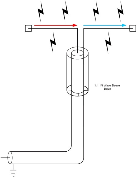
You are correct. If one compares the Pawsey stub with a
1/4 wave, de-coupling sleeve or "sleeve balun" as shown in Wikipedia:
[img]cid:.0[/img]
. . . we see that the top end of the sleeve is the open end
of a shorted 1/4-wave transmission line. I.e., the
impedance of the top rim of the sleeve looking at the
shorted end is very high. Hence, connecting it to the
center conductor adds no 'load' to purposeful energy
but it would have the effect of collecting differential
currents between coax shield and the center conductor
and force them toward equivalency.
The Pawsey stub functions in the same manner except that
its behavior is more like a short piece of balanced
transmission line as opposed to a piece of coax. This
brings to light an error in my balun article cited
earlier. Since the stub IS NOT operating as a free-space
1/4-wave but instead as a transmission line, dielectric
effects on velocity come into play. The velocity factor
of this piece of transmission line is on the order of
.95 to .97 which means that my 26" dimension for the
stub would be closer to optimum were it shortened by
an inch or so.
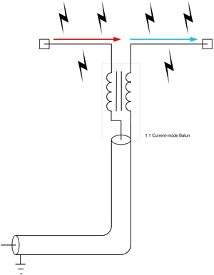
The 'coiled coax ploy" has good foundations
in physics. Consider this image from the Wikipedia
article:
[img]cid:.1[/img]
The current balun is a common mode choke which
may be implemented by wires on a high-efficiency
core (as in many TV couplers), a coil of coax
immediately adjacent to the attach point on the
dipole or consider this image also from Wikipedia
article on baluns:
[img]cid:.2[/img]
As you can see here, the common mode choke effects
are greatly enhanced by winding the coax onto
the core. Inductance in these windings is proportional
to the permeability of the magnetic path material.
Air is 1.0, the ferrite may be 5-20 . . . thus
multiplying the beneficial effects by that factor.
The neat thing about this balun is that it is not
resonant or tuned; thus effective over a wider range
of frequencies. The stubs in coax or balanced transmission
lines are tuned and optimum at one frequency only.
The 'hard' thing about the coax on core ploy is finding
coax that will wind tightly through a relatively
small core WITHOUT dropping below the recommended
bend radius for that coax. Coaxes with solid center
conductors are at risk for center conductor migration
through the insulation over time and temperature
cycles. RG-141 wound through a core like that has
potential for becoming a shorted feed line years from
now. The commercial antenna I saw with this technique
used a small diameter, very flexible coax and offered
a BNC connector on the stub for extending the feed line
to the appliance with more conventional coax.
Bob . . .
| | - The Matronics AeroElectric-List Email Forum - | | | Use the List Feature Navigator to browse the many List utilities available such as the Email Subscriptions page, Archive Search & Download, 7-Day Browse, Chat, FAQ, Photoshare, and much more:
http://www.matronics.com/Navigator?AeroElectric-List |
|
| Description: |
|
| Filesize: |
36.54 KB |
| Viewed: |
15350 Time(s) |
|
| Description: |
|
| Filesize: |
20.83 KB |
| Viewed: |
15350 Time(s) |
|
| Description: |
|
| Filesize: |
34.26 KB |
| Viewed: |
15350 Time(s) |
|
|
|
| Back to top |
|
|
jan_de_jong(at)casema.nl
Guest
|
| Posted: Mon Feb 27, 2012 9:38 am Post subject: Dipole antenna fabrication |
|
|
Bob, thank you for the explanation.

There was some discussion on the web whether the velocity factor to be

used for finding the length of the Pawsey stub was that for the coax

insides (NO) or the coax outsides (YES). The latter would be the .97 to

.99 then.


Jan
| | - The Matronics AeroElectric-List Email Forum - | | | Use the List Feature Navigator to browse the many List utilities available such as the Email Subscriptions page, Archive Search & Download, 7-Day Browse, Chat, FAQ, Photoshare, and much more:
http://www.matronics.com/Navigator?AeroElectric-List |
|
|
|
| Back to top |
|
|
Float Flyr
Joined: 19 Jul 2006
Posts: 2704
Location: Campbellton, Newfoundland
|
| Posted: Mon Feb 27, 2012 2:26 pm Post subject: Dipole antenna fabrication |
|
|
Dipole antenna erected vertically is similar to the 1/4 wave whip that we

now use.  The tricks are to make sure you have a large enough groundplane

(section of the aircraft skin).  When I first saw the talk of dipole

antennae I assumed incorrectly you wanted to be able to remove a radio and

take it with you and still have good range in case of a crash.


Aircraft radios are restricted to power.  Basically the powers to be don't

want you to be transmitting thousands of miles otherwise they would up the

power of transceivers and drop the frequency closer to six meters than to

two meters.  Main problem with that is you could end up with a lot of

crosstalk like they used to have on the CB band  (11 meters).


While flying in mountainous areas for safety I would not be without the new

400 mHz ELT.  There are lots of things about those ELTs I don't like but we

are stuck with it.


Noel

--
| | - The Matronics AeroElectric-List Email Forum - | | | Use the List Feature Navigator to browse the many List utilities available such as the Email Subscriptions page, Archive Search & Download, 7-Day Browse, Chat, FAQ, Photoshare, and much more:
http://www.matronics.com/Navigator?AeroElectric-List |
|
_________________
Noel Loveys
Kitfox III-A
Aerocet 1100 Floats |
|
| Back to top |
|
|
Float Flyr
Joined: 19 Jul 2006
Posts: 2704
Location: Campbellton, Newfoundland
|
| Posted: Mon Feb 27, 2012 2:28 pm Post subject: Dipole antenna fabrication |
|
|
"Good enough" is everyone's enemy when it comes to ceasing to operate at

3000' !

Noel


--
| | - The Matronics AeroElectric-List Email Forum - | | | Use the List Feature Navigator to browse the many List utilities available such as the Email Subscriptions page, Archive Search & Download, 7-Day Browse, Chat, FAQ, Photoshare, and much more:
http://www.matronics.com/Navigator?AeroElectric-List |
|
_________________
Noel Loveys
Kitfox III-A
Aerocet 1100 Floats |
|
| Back to top |
|
|
Float Flyr
Joined: 19 Jul 2006
Posts: 2704
Location: Campbellton, Newfoundland
|
| Posted: Mon Feb 27, 2012 3:17 pm Post subject: Dipole antenna fabrication |
|
|
Bob:


 Have you ever used a broadband windom antenna?


Noel


--
| | - The Matronics AeroElectric-List Email Forum - | | | Use the List Feature Navigator to browse the many List utilities available such as the Email Subscriptions page, Archive Search & Download, 7-Day Browse, Chat, FAQ, Photoshare, and much more:
http://www.matronics.com/Navigator?AeroElectric-List |
|
_________________
Noel Loveys
Kitfox III-A
Aerocet 1100 Floats |
|
| Back to top |
|
|
nuckolls.bob(at)aeroelect
Guest
|
| Posted: Mon Feb 27, 2012 8:39 pm Post subject: Dipole antenna fabrication |
|
|
At 05:12 PM 2/27/2012, you wrote:
| Quote: |
Bob:
Have you ever used a broadband windom antenna?
|
No, I've known hams that did. Most of my activity
for the past 40 years has been on 2M repeaters.
In the picture at . . .
http://aeroelectric.com/Pictures/Misc/KTVH.jpg
you can see the toes of my boots while peering
down the center of KTVH tower east of Hutchinson
KS. I was standing on the 1200' platform were
the 22/82 repeater was quartered back then.
Antennas to die for on that system were things
like DB-228 arrays of 8 dipoles on a mast about
40' long and weighing in at 75 pounds. Got to
hang two of those off the leg of this tower
about 100' apart.
Bob . . .
| | - The Matronics AeroElectric-List Email Forum - | | | Use the List Feature Navigator to browse the many List utilities available such as the Email Subscriptions page, Archive Search & Download, 7-Day Browse, Chat, FAQ, Photoshare, and much more:
http://www.matronics.com/Navigator?AeroElectric-List |
|
|
|
| Back to top |
|
|
Eric M. Jones
Joined: 10 Jan 2006
Posts: 565
Location: Massachusetts
|
| Posted: Tue Feb 28, 2012 5:39 am Post subject: Re: Dipole antenna fabrication |
|
|
| Quote: | Bob N. said: But you paint a picture suggesting that a balun would make the difference between communicating with some distant
station . . . and not. |
No, I didn't. Not at all. But I've flown across western stretches (Try Bishop to Death Valley, pardner...). No Radar, no flight following, no radio communication of any kind. I've also flown all over Mexico, where radio relay from plane-to-plane-station is how it's done. In Baja, communications with the mainland is typical...and very hard...but HEY, it's line of sight!
I am glad to see others post good info. There are many Hams out there who are quite skilled in this area. Thanks Jan de Jong. I'll be building one of those for my Glastar's vertical stab.
If local ops and $100 hamburgers is all you do, Bob N. is right. If you want better performance for little extra effort, then I'm right.
| | - The Matronics AeroElectric-List Email Forum - | | | Use the List Feature Navigator to browse the many List utilities available such as the Email Subscriptions page, Archive Search & Download, 7-Day Browse, Chat, FAQ, Photoshare, and much more:
http://www.matronics.com/Navigator?AeroElectric-List |
|
_________________
Eric M. Jones
www.PerihelionDesign.com
113 Brentwood Drive
Southbridge, MA 01550
(508) 764-2072
emjones(at)charter.net |
|
| Back to top |
|
|
nuckolls.bob(at)aeroelect
Guest
|
| Posted: Tue Feb 28, 2012 11:54 am Post subject: Dipole antenna fabrication |
|
|
At 07:39 AM 2/28/2012, you wrote:


 > Bob N. said: But you paint a picture suggesting that a balun would

make the difference between communicating with some distant station .

. . and not.

No, I didn't. Not at all.


   . . . I'm confused . . .

But I've flown across western stretches (Try Bishop to Death Valley,

pardner...). No Radar, no flight following, no radio communication of

any kind. I've also flown all over Mexico, where radio relay from

plane-to-plane-station is how it's done. In Baja, communications with

the mainland is typical...and very hard...but HEY, it's line of sight!


   Okay, we're talking about fringe communications . . .


I am glad to see others post good info. There are many Hams out there

who are quite skilled in this area. Thanks Jan de Jong. I'll be

building one of those for my Glastar's vertical stab.


If local ops and $100 hamburgers is all you do, Bob N. is right. If

you want better performance for little extra effort, then I'm right.


    I didn't know it was a right/wrong contest

    but an quantitative evaluation of return on

    investment. Did you agree that adding a balun

    is unlikely to produce any observable effect

    . . . yet hamburger runs makes Bob 'right'

    and 'extra performance' makes him wrong

    . . . ?????


    Just for grins I went to the bench and set up

    a receiver for 130MHz and turned on the HP

    generator set for 30% AM modulation. I opened

    the squelch and turned the radiated signal up

    until I could just barely tell that there was

    a modulated signal competing with the receiver's

    noise floor at (0.10 uV); a reasonable simulation

    of 'extreme fringe' communications.


    I turned the signal up until I was reasonably

    certain that I could deduce spoken words on

    a still very noisy signal. It took 0.2 to 0.33 uV

    (6 to 20 dB increase) to make that much difference.

    Were I trying to carry on meaningful conversation

    with cockpit ambients added in . . . maybe that

    wouldn't have been enough.


    If one compares balun vs. no-balun characteristics,

    what factor of 'better performance' would you expect?

   Bob . . .
| | - The Matronics AeroElectric-List Email Forum - | | | Use the List Feature Navigator to browse the many List utilities available such as the Email Subscriptions page, Archive Search & Download, 7-Day Browse, Chat, FAQ, Photoshare, and much more:
http://www.matronics.com/Navigator?AeroElectric-List |
|
|
|
| Back to top |
|
|
|
|
You cannot post new topics in this forum
You cannot reply to topics in this forum
You cannot edit your posts in this forum
You cannot delete your posts in this forum
You cannot vote in polls in this forum
You cannot attach files in this forum
You can download files in this forum
|
Powered by phpBB © 2001, 2005 phpBB Group
|

