 |
Matronics Email Lists
Web Forum Interface to the Matronics Email Lists
|
| View previous topic :: View next topic |
| Author |
Message |
fireflier
Joined: 24 Jun 2012
Posts: 58
|
 Posted: Sat Nov 24, 2012 5:02 pm Post subject: tri gear socket installation Posted: Sat Nov 24, 2012 5:02 pm Post subject: tri gear socket installation |
 |
|
Hello
Today I have been busy trial fitting my gear sockets. but I have got a problem and wondered if anyone has experience this during building and how they have overcome it?
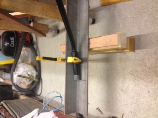
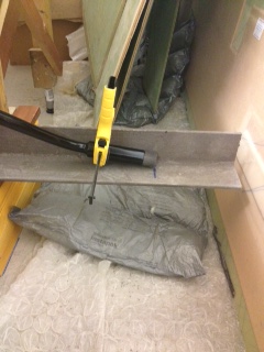
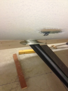
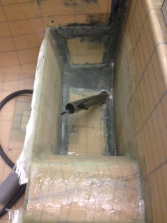
After taking my time setting everything up as per the build manual I inserted the gear legs and sockets into the holes clamping the axle's in position against angled bar with the axle center line on fuselage station 70 and the axle end 36.75'' from the fuselage center line. With all this set up the socket flanges are approx 13 - 15 mm of the fuselage.
I tried altering the fuselage underside to ground height but this made very little difference to the distance between socket flanges and the fuselage. I managed to get the gap down to approx 5-8mm by reducing the fuselage underside to ground height to 395mm, this is very different to the 413mm quoted in the build manual.
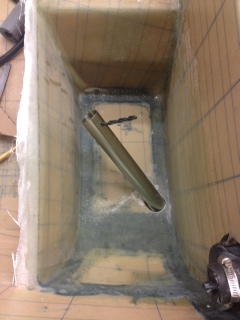
I have attached some photos showing the gap between sockets and fuselage and also the position of the socket tubes within the baggage bays when inserted.
Any comments or solutions to my problem would be much appreciated.
Many thanks for taking the time in trying to help me find a solution to the problems I'm experiencing.
Kind regards
Donald
| | - The Matronics Europa-List Email Forum - | | | Use the List Feature Navigator to browse the many List utilities available such as the Email Subscriptions page, Archive Search & Download, 7-Day Browse, Chat, FAQ, Photoshare, and much more:
http://www.matronics.com/Navigator?Europa-List |
|
| Description: |
|
| Filesize: |
40.41 KB |
| Viewed: |
6652 Time(s) |
|
| Description: |
|
| Filesize: |
33.76 KB |
| Viewed: |
6652 Time(s) |
|
| Description: |
| starboard socket position |
|
| Filesize: |
30.01 KB |
| Viewed: |
6652 Time(s) |
|
| Description: |
|
| Filesize: |
23.9 KB |
| Viewed: |
6652 Time(s) |
|
| Description: |
|
| Filesize: |
32.03 KB |
| Viewed: |
6652 Time(s) |
|
| Description: |
|
| Filesize: |
23.15 KB |
| Viewed: |
6652 Time(s) |
|
_________________
Fireflier |
|
| Back to top |
|
 |
craigb(at)onthenet.com.au
Guest
|
| Posted: Sat Nov 24, 2012 5:48 pm Post subject: tri gear socket installation |
|
|
How long are your sockets from the bolt hole, to bottom of the tube, at the

rear of the socket eg near the tail

Mine measure at 245mm (9.5 inches), perhaps yours are longer than they

should be.


My gap when installed was about 4mm.


Regards

craig
| | - The Matronics Europa-List Email Forum - | | | Use the List Feature Navigator to browse the many List utilities available such as the Email Subscriptions page, Archive Search & Download, 7-Day Browse, Chat, FAQ, Photoshare, and much more:
http://www.matronics.com/Navigator?Europa-List |
|
|
|
| Back to top |
|
|
neveyre(at)aol.com
Guest
|
| Posted: Sun Nov 25, 2012 12:57 am Post subject: tri gear socket installation |
|
|
Hi Donald,

   1/2'' to 5/8'' gaps betwen the socket flange and the outer skin is not unusual, I could never work out where the variation came from ?

   Most important is the ST 70 dimension.

   Then ensure the track is true with the legs clamped to an angle straight edge.Take measurements from tailplane torque tube ends to check this.

   Then ensure the horizontal datum of the angle aligns with the aircrafts horizontal datum [ tailplane torque tube / wing spar bushes ].

   Then check the lateral position from the aircrafts centre line [ also check the positive camber of the axle shafts and adjust [ worsen] the side to side positioning to get the camber of the shafts nearer to each other.

   Forget about closing up the gap between the socket flanges and the fuselage skin.

   If you can close up the gap [ dropping the fuselage ] without buggering up any of the other parameters, well and good, otherwise go for it and use a thick Redux pad in the gap. I have slipped in some plywood shims to bulk out the gap if it as large as you describe [ Redux is expensive, slivers of wood will be free !]

   Other things I do different, the lay up of the socket to Rib 1, don't smear Redux on the socket and do the lay up with Ampreg, do a HOT Redux lay up in 1 ply of Bid, 2'' onto each side of the Rib around the socket, peel ply and let cure. Then do the lay ups as per Manual.

   Do a hot Redux lay up on the outer face of the socket flange, peel ply etc, before doing the 2 Bid lay up on to the skin. Do the hot Redux lay ups onto plastic sheet, wet out well, then slap it on like an elastoplast !

   Ampreg doesn't stick too well to steel, and I don't like messing with two different epoxy systems  going wet on wet ?

   Cheers,

   Nev.


   --
| | - The Matronics Europa-List Email Forum - | | | Use the List Feature Navigator to browse the many List utilities available such as the Email Subscriptions page, Archive Search & Download, 7-Day Browse, Chat, FAQ, Photoshare, and much more:
http://www.matronics.com/Navigator?Europa-List |
|
|
|
| Back to top |
|
|
jglazener
Joined: 14 Apr 2010
Posts: 76
Location: Schoonhoven, Netherlands
|
| Posted: Sun Nov 25, 2012 6:41 am Post subject: Re: tri gear socket installation |
|
|
Donald,


Obviously, writing a post after Nev I have little to add on how to do things right. I did  however have the same problem and in my case at least it turned out to be faulty measurements. There are quite a few variables and any one of them can knock the measurements off. My garage for instance has a drain in the middle and the floors slope very slightly towards that. I ended up having to grind the whole lot out again. The second time round the plates did fit against the skin. It really is worth checking everything 10 times to avoid that.


See:


http://www.europaowners.org/main.php?g2_itemId=44767


Regards,
| | - The Matronics Europa-List Email Forum - | | | Use the List Feature Navigator to browse the many List utilities available such as the Email Subscriptions page, Archive Search & Download, 7-Day Browse, Chat, FAQ, Photoshare, and much more:
http://www.matronics.com/Navigator?Europa-List |
|
_________________
Jeroen
http://www.europaowners.org/main.php?g2_itemId=44165 |
|
| Back to top |
|
|
frans(at)privatepilots.nl
Guest
|
| Posted: Sun Nov 25, 2012 7:32 am Post subject: tri gear socket installation |
|
|
On 11/25/2012 03:41 PM, jglazener wrote:
| Quote: | Obviously, writing a post after Nev I have little to add on how to do
things right. I did however have the same problem and in my case at
least it turned out to be faulty measurements. There are quite a few
variables and any one of them can knock the measurements off. My
garage for instance has a drain in the middle and the floors slope
very slightly towards that.
|
To avoid this problem I welded two vertical bars to my build craddle
with adjustable ends, so I could attach an artificial floor straight
edge to it, and adjust everything independantly from the floor. This
might be a solution for you if your floor is not perfectly even, or when
you use a movable build craddle.
Also make sure you end up with some degree of toe in on the axles, as
the aircraft weight and roll friction will push the wheels outward a
little. This prevents the problem that the tires wear prematurely on the
inboard side. (After 200 hours, I still have even wear on the tires,
never had to swap or reverse them).
| Quote: | It really is worth checking everything 10 times to avoid that.
|
Yep, don't rush it. It is hard to readjust later on.
Frans
| | - The Matronics Europa-List Email Forum - | | | Use the List Feature Navigator to browse the many List utilities available such as the Email Subscriptions page, Archive Search & Download, 7-Day Browse, Chat, FAQ, Photoshare, and much more:
http://www.matronics.com/Navigator?Europa-List |
|
|
|
| Back to top |
|
|
kjburns(at)btinternet.com
Guest
|
| Posted: Sun Nov 25, 2012 12:04 pm Post subject: tri gear socket installation |
|
|
Donald,


The build manual says:-


"If necessary, to ensure that the plate of the gear leg socket is against the side of the fuselage,move the


axles as required relative to the fuselage centreline keeping the axle centres on FS70".


By moving the legs in 1/2 an inch or so equaly on each side , you will close up the gap to a wedge shape, the manual also sugests the socket flanges can be adjusted to fit the profile better.


My fit was close enougth�for an acceptable redux filling, after adjusting the fuselage holes slightly, but it does appears that your legs need to come together slightly .


There will be differences in exact positioning of the sockets due variations  to the elogation required of the hole.


Two extra check measurement that I found usefull were from a second angle iron ran through the cockpit, sat on the door sills,pushed hard against the seat back, and dropped a plumbline from the inboard end to find a  measurement from the spar face reference points :-


Not e :  F S 70 is 2.25" aft of the forward face of the port spar     �           �          1.00 aft of the forward face of the Starboard spar. Mark up the fuselage to get a measurement to transfer from your second angle iron / plumb line, stick a spirit level on the angle Iron to check it is all parallel when setting up , and stand back an look at the job, making sure it is all square... Also, make sure your build cradle is squared off on all corners, and can not move. I set up a false floor with 3 layers  of 3/4 ply,screwed down onto a pallet, with a timber beam accross to screw down and clamp on, you will end up spending days setting your measurements unless everything is fastened down solid. Finaly, you can do a dry run by lifting the sockets and legs to a flush position ,an using the first wedge shaped ply brace, hold the assembly in possition , then look at the axle to see how far in it is sitting . You are trying to acheive aligned axles on FS 70, within the factory height specified (prop clearance)� 1/2 " or so different track width will make no significant difference, and is the factory recomended solution per the manual. Regards  Kevin


  From: fireflier <fireflier(at)btinternet.com>

 To: europa-list(at)matronics.com

 Sent: Sunday, 25 November 2012, 1:02

 Subject: Europa-List: tri gear socket  installation


--> Europa-List message posted by: "fireflier" <fireflier(at)btinternet.com (fireflier(at)btinternet.com)>


Hello


Today I have been busy trial fitting my gear sockets. but I have got a problem and wondered if anyone has experience this during building and how they have overcome it?


After taking my time setting everything up as per the build manual I inserted the gear legs and sockets into the holes clamping the axle's in position against angled bar with the axle center line on fuselage station 70 and the axle end 36.75' from the fuselage center line.  With all this set up the socket flanges are approx 13 - 15 mm of the fuselage.


I tried altering the fuselage underside to ground height but this made very little difference to the distance between socket flanges and the fuselage.  I managed to get the gap down to approx  5-8mm by reducing the fuselage underside to ground height to 395mm, this is very different to the 413mm quoted in the build manual.


I have attached some photos showing the gap between sockets and fuselage and also the position of the socket tubes within the baggage bays when inserted.


Any comments or solutions to my problem would be much appreciated.


Many thanks for taking the time in trying to help me find a solution to the problems I'm experiencing.


Kind regards

Donald


--------

Fireflier


Read this topic online here:


http://forums.matronics.com/viewtopic.php?p=388820#388820


Attachments:


http://forums.matronics.com//files/port_axle_494.jpeg

http://forums.matronics.com//files/starboard_axle_172.jpeg

http://forums.matronics.com//files/starboard_socket_position_in_baggage_bay_539.jpeg

http://forums.matronics.com//files/starboard_leg_socket_188.jpg

http://forums.matronics.com//files/port_socket_position_in_baggage_bay_886.jpg

http://forums.m//www.matronics.com/contribution" target="_blank">http://www.matronics.cosp;               -Matt Dralle, List =   --> http://www.matronics.com/Navigator?Europa-List

_ref="http://forums.matronics.com/" target="_blank">http://forums.matron===================


 [quote][b]
| | - The Matronics Europa-List Email Forum - | | | Use the List Feature Navigator to browse the many List utilities available such as the Email Subscriptions page, Archive Search & Download, 7-Day Browse, Chat, FAQ, Photoshare, and much more:
http://www.matronics.com/Navigator?Europa-List |
|
|
|
| Back to top |
|
|
budyerly(at)msn.com
Guest
|
| Posted: Sun Nov 25, 2012 12:07 pm Post subject: tri gear socket installation |
|
|
<?xml:namespace prefix="v" /><?xml:namespace prefix="o" /><![endif]-->  Nev, Donald, and others having tri gear concerns.


 Nev is right that the gap is really not that much of a concern especially  at 5-8 mm.   Organizing the project for efficiency of work comes with  practice.


 The adjustment of the height of the fuselage to gear plane is one excellent  way to make and adjustment to the fit.  Just don't get too carried away,  keep it close to the vertical distance in the book, which keeps the tail from  being too low (nose gear higher means banging it more often) or too high which  increases the camber angle making tire wear increase.


 I do bend the flanges a bit to allow me not to have to use as much  Redux.  Then just bond it in.


 Unlike Nev, I prefer to glue in the cleaned and dimpled metal sockets first  and allow to cure, then  put in Rib one the next day.  If working  alone, I put in both rib ones and let them partially cure, getting a long coffee  break.  If working with an assistant, we return when the ribs are firm and  apply Aeropoxy or Ampreg flox to fill the gaps at the walls and smooth our  Redux job a bit and apply more Redux to the leg face for a good bond and follow  with the number one layups. If we are making good time, we lay on rib two with  Redux then take a quick lunch break.  We come back and while the Redux  is a bit sticky but the rib is in firmly, we lay in more flox and glass it  up.  Then I allow it to cure with a bit of peel ply.  That makes  for a really long day though.


 However, if you're not on with your glassing MOJO, as the kids say,  then I do rib two the next day.    Of course you can gather that  the one and two ribs are carefully cut to a tight fit and ready to install  before hand.  In a perfect world, the next day I do the trimming of the  three and four ribs and install them.  Your back will really need a break  when done.   Then take the gear out and glass in the bottom.


 If working alone, and if the top is on already, work gets slowed down a  bit, so one rib a day is normally the rule.  It is getting winter time, so  heating of the project is necessary so it also tends to slow the project a  bit.


 From start to finish, one week to get the plane level and set, ribs in and  legs on.  That leaves the next week to get the wheels and brakes in and  operating, and the plane rolling.  Week three is needed for the wheel pants  and such.  Then you need a much deserved break but only a short one, as  there is more to do.  Getting the monowheel hole closed up and figure how  to get a lower access hole installed and fuel lines cleaned up and  accessories in that big old cockpit module hole.


 Regards,

 Bud Yerly

 [quote]   ---
| | - The Matronics Europa-List Email Forum - | | | Use the List Feature Navigator to browse the many List utilities available such as the Email Subscriptions page, Archive Search & Download, 7-Day Browse, Chat, FAQ, Photoshare, and much more:
http://www.matronics.com/Navigator?Europa-List |
|
|
|
| Back to top |
|
|
fireflier
Joined: 24 Jun 2012
Posts: 58
|
| Posted: Mon Nov 26, 2012 11:51 pm Post subject: tri gear socket installation |
|
|
Hi all

Many thanks for all your replies much appreciated and has put my mind to rest that all appears normal with the installation of my tri gear sockets.

Not had a chance to go back and re check everything again but will check over everything another few times before taking the plunge & bonding in the sockets.

Many thanks for all the comments & suggestions on doing the rest of the process as well, they are all very useful and gives me different options to complete the tri gear installation.

Kind regards

Donald


Sent from my iPhone


On 25 Nov 2012, at 20:07, "Bud Yerly" <budyerly(at)msn.com (budyerly(at)msn.com)> wrote:

[quote]      <?xml:namespace prefix="v" /><?xml:namespace prefix="o" /><![endif]-->  Nev, Donald, and others having tri gear concerns.


 Nev is right that the gap is really not that much of a concern especially  at 5-8 mm.   Organizing the project for efficiency of work comes with  practice.


 The adjustment of the height of the fuselage to gear plane is one excellent  way to make and adjustment to the fit.  Just don't get too carried away,  keep it close to the vertical distance in the book, which keeps the tail from  being too low (nose gear higher means banging it more often) or too high which  increases the camber angle making tire wear increase.


 I do bend the flanges a bit to allow me not to have to use as much  Redux.  Then just bond it in.


 Unlike Nev, I prefer to glue in the cleaned and dimpled metal sockets first  and allow to cure, then  put in Rib one the next day.  If working  alone, I put in both rib ones and let them partially cure, getting a long coffee  break.  If working with an assistant, we return when the ribs are firm and  apply Aeropoxy or Ampreg flox to fill the gaps at the walls and smooth our  Redux job a bit and apply more Redux to the leg face for a good bond and follow  with the number one layups. If we are making good time, we lay on rib two with  Redux then take a quick lunch break.  We come back and while the Redux  is a bit sticky but the rib is in firmly, we lay in more flox and glass it  up.  Then I allow it to cure with a bit of peel ply.  That makes  for a really long day though.


 However, if you're not on with your glassing MOJO, as the kids say,  then I do rib two the next day.    Of course you can gather that  the one and two ribs are carefully cut to a tight fit and ready to install  before hand.  In a perfect world, the next day I do the trimming of the  three and four ribs and install them.  Your back will really need a break  when done.   Then take the gear out and glass in the bottom.


 If working alone, and if the top is on already, work gets slowed down a  bit, so one rib a day is normally the rule.  It is getting winter time, so  heating of the project is necessary so it also tends to slow the project a  bit.


 From start to finish, one week to get the plane level and set, ribs in and  legs on.  That leaves the next week to get the wheels and brakes in and  operating, and the plane rolling.  Week three is needed for the wheel pants  and such.  Then you need a much deserved break but only a short one, as  there is more to do.  Getting the monowheel hole closed up and figure how  to get a lower access hole installed and fuel lines cleaned up and  accessories in that big old cockpit module hole.


 Regards,

 Bud Yerly

 [quote]   ---
| | - The Matronics Europa-List Email Forum - | | | Use the List Feature Navigator to browse the many List utilities available such as the Email Subscriptions page, Archive Search & Download, 7-Day Browse, Chat, FAQ, Photoshare, and much more:
http://www.matronics.com/Navigator?Europa-List |
|
_________________
Fireflier |
|
| Back to top |
|
|
phillik747
Joined: 04 Apr 2012
Posts: 73
Location: Birminham, AL USA
|
| Posted: Tue Dec 04, 2012 7:26 am Post subject: Re: tri gear socket installation |
|
|
| frans(at)privatepilots.nl wrote: |
Also make sure you end up with some degree of toe in on the axles, as
the aircraft weight and roll friction will push the wheels outward a
little. This prevents the problem that the tires wear prematurely on the
inboard side. (After 200 hours, I still have even wear on the tires,
never had to swap or reverse them).
Frans |
How much tow in are you talking about? I'm setting mine up now and is see there is a natural tendency for them to toe in a little but before I bond it all in I wanted to see how much is enough.
Thanks,
Kyle
| | - The Matronics Europa-List Email Forum - | | | Use the List Feature Navigator to browse the many List utilities available such as the Email Subscriptions page, Archive Search & Download, 7-Day Browse, Chat, FAQ, Photoshare, and much more:
http://www.matronics.com/Navigator?Europa-List |
|
_________________
Kyle
Europa Tri-gear (under construction) |
|
| Back to top |
|
|
|
|
You cannot post new topics in this forum
You cannot reply to topics in this forum
You cannot edit your posts in this forum
You cannot delete your posts in this forum
You cannot vote in polls in this forum
You cannot attach files in this forum
You can download files in this forum
|
Powered by phpBB © 2001, 2005 phpBB Group
|

