nuckolls.bob(at)aeroelect
Guest
|
 Posted: Fri Oct 04, 2013 6:36 am Post subject: Dual voltage output from fuel quantity senders Posted: Fri Oct 04, 2013 6:36 am Post subject: Dual voltage output from fuel quantity senders |
 |
|
At 03:26 PM 10/3/2013, you wrote:
| Quote: | --> AeroElectric-List message posted by: Peter Pengilly <peter(at)sportingaero.com>
I have 2 fuel gauges in my airplane that work on 12v and 5v, and only one (resistance type) sender. I am trying to figure out how to get both gauges to work and be accurate. The 12v gauge is a straight analogue device with a pointer. The 5v gauge is part of an EFIS. At present I am using the analogue gauge only and the EFIS is continually upset at having no fuel quantity input.
I have looked into a solution using an Arduino, sampling the data in doesn't seem to be too difficult, using the analogue input and a voltage divider circuit to drop the input voltage. I think I can get the Arduino to drive something like a MCP41100 8 bit dual digital potentiometer as an output device, with the 2 channels one for each of the 12v & 5v circuits. However these devices work at 5v and low current.
So my question to the smart people here is how to I use the output of these digipots to look to the gauges as though they are a 30-240 ohm fuel quantity sender? |
Assumptions:
The input to your EFIS is 0-5 volts, high
impedance with zero volts = zero fuel.
The 30-240 ohm sender is minimum resistance
at full fuel.
The characteristics of your steam gauge are
unknown but it's certain that the gauge is not
a 'sensitive' voltmeter (i.e. movement that
reads micro-amps). You need to hook it up
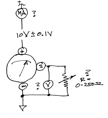
on the bench like this and take some measurements:
[img]cid:.0[/img]
Make a chart of instrument current draw,
S-terminal voltage, and 'Sender' resistance
for zero fuel, 1/4 fuel, 1/2 fuel, 3/4 fuel,
and full fuel.
I'm pretty sure you can do all that needs to
be done with analog components (op amps etc)
but we first need to characterize the steam
guage . . . this is a bit like the game where
somebody hands you a little box with 2 or more
terminals on it. You get to 'probe' the box
by measuring at the external terminals. The
challenge is to describe what's inside the
box.
This task is a little simpler, we only need
to know the DC characteristics of the guage
for indications it THINKS are coming from
the companion sensor end the tank. Yeah,
that 10v supply is on purpose, we'll endeavor
to regulate power to the guage for better
prediction of the design.
In fact, do the experiment twice, the second
time with say 8 volts applied to the guage
and see what those numbers are too.
Bob . . .
| | - The Matronics AeroElectric-List Email Forum - | | | Use the List Feature Navigator to browse the many List utilities available such as the Email Subscriptions page, Archive Search & Download, 7-Day Browse, Chat, FAQ, Photoshare, and much more:
http://www.matronics.com/Navigator?AeroElectric-List |
|
| Description: |
|
| Filesize: |
33.36 KB |
| Viewed: |
596 Time(s) |

|
|
|


