 |
Matronics Email Lists
Web Forum Interface to the Matronics Email Lists
|
| View previous topic :: View next topic |
| Author |
Message |
nuckolls.bob(at)aeroelect
Guest
|
 Posted: Mon Mar 17, 2014 10:21 am Post subject: New Over-Voltage Protection Architecture Posted: Mon Mar 17, 2014 10:21 am Post subject: New Over-Voltage Protection Architecture |
 |
|
| Quote: | Great idea. Thanks Bob
My RV-12 has a permanent magnet alternator. So I can not try out
the series resistor idea. I like to think about alternative ways of
wiring an airplane. Most of the time, the old way is the best way.
|
ALL ways are worthy of considered thought.
It's just as valuable to know what DOES work
as those things which are QUESTIONABLE.
I've often asked builders to get on the List
and tell us what was tried that didn't work . . .
like Bob's posting on EarthX . . .
It helps avoid discovering a bad idea over and
over again!
Bob . . .
| | - The Matronics AeroElectric-List Email Forum - | | | Use the List Feature Navigator to browse the many List utilities available such as the Email Subscriptions page, Archive Search & Download, 7-Day Browse, Chat, FAQ, Photoshare, and much more:
http://www.matronics.com/Navigator?AeroElectric-List |
|
|
|
| Back to top |
|
 |
nuckolls.bob(at)aeroelect
Guest
|
| Posted: Tue Mar 18, 2014 7:51 am Post subject: New Over-Voltage Protection Architecture |
|
|
At 08:17 AM 3/18/2014, you wrote:

 --> AeroElectric-List message posted by: "Eric M. Jones" <emjones(at)charter.net>


 Joe,


 Before you reinvent anything, let me show you my Proposed Perihelion Power Protector (attached).


 Repost from 20JUL07: (time flys...)


  I talk to many builders who are particularly concerned about frying their expensive avionics and glass panels. These parts are typically 1/3 of the airplane cost.


 Planning the wiring of a small aircraft involves installing systems to safeguard the buses against failure of the alternator. Either an internally regulated alternator or its more adaptable brother with an external regulator still has the potential problem of a runaway condition, as well as a short circuit of the main battery to alternator B-lead, and frequent load dump OV conditions.


          "frequent"?


 Linear Technology has introduced a clever device, the LT4356-1 Overvoltage Protection Regulator and Inrush Limiter to address all these worries.


         . . . but are they real worries . . .


         We had an extended discussion on 'load dumps' here

         on the List back about 2004. A sampling of the

         work product during those conversations can be

         accessed at . . .


  http://tinyurl.com/ngu7ptq


         Load dump speaks to the naturally occurring response

         of the engine driven power source, its regulator

         and perhaps the ship's battery to a sudden reduction of a

         large load . . . like an air conditioner pump

         motor, landing gear hydraulic pump motor, etc.


         Another case supposes that a battery is not present

         or becomes UNHOOKED during this heavy-load reduction.

         Not only does the alternator/generator become suddenly

         UNLOADED . . . the system may also be deprived of it's #1

         load dump MITIGATOR . . . the battery.


         This condition is addressed in DO-160/Mil-STD-704

         as a recommendation designing a 14v product to

         stand off 20V for 1S, 40V for 100mS. Double the

         voltages for a 28V system. This is the time

        it takes for an equally qualified OV management

         system to corral the aberrant energy source and

         bring the event to a graceful conclusion.


         You will find the LT4356 cited in the constellation

         of Google hits in the link cited above. This device

         is but one of MANY approaches to achieving load-dump

         robustness in aircraft. I've been testing to DO-160/

          Mil-STD-704 for 40+ years and never found it necessary

         to go to such extremes in parts count to protect the

         input power port of my proposed appliance.


         I'm not suggesting that the LT4356 does not perform

         as advertised but I will suggest that it's an

         inelegant solution to a problem that been the least

         of our design challenges for decades.


         I suggest that load-dump stresses that fall outside

         the time honored design goals don't happen . . .

         Recall how many times I've written about the paucity

         of accidents having root cause in electrical system

         issues. Of the few which did have electrically fertilized

         roots, load-dump damage was not among them.


         Further, how many installation manuals for your $high$ electro-

         whizzies suggest any need to mitigate transient effects

         above and beyond the DO-169 stresses to which they

         have already qualified their product?


         Can you imagine the cries out of the darkness and

         renting of clothes should some big name like Garmin

         hold forth with such a recommendation? Such an

         assertion would mean one or both of two things (1)

         DO-160 was found lacking or (2) Garmin was unable to

         design to DO-160 design goals. You would be less

         scorned if they predicted that the sun would rise

         in the north tomorrow or that water molecule of H3O2

         is predicted to freeze at 50C.


         I did a pitch trim controller for the Lear 30/50

         series airplanes that would stand off 80 volts for

         tens if seconds . . . not milliseconds . . . it was no

         big deal. My biggest challenge in that design was

         to beat the parts count down in a worry-mitigation

         watch-dog with about twice the parts count

         of the controller. Over the years, failures in the

         system were predominantly in the watch-dog

         . . . not the controller.


         The point being that one should be cautious when

         taking on new worries about spikes, surges, bumps,

         dumps, wiggles and jiggles on the bus that have

         been pretty well understood for a long time. We

         can look back at pyramid builders and marvel at

         their cleverness and knowledge . . . but for them

         it was all in a day's work.


  http://tinyurl.com/n3swgjr


         For those of us who made a vocation of simple, low cost,

         robust designs in electrical systems . . . it's

         all in a days work. The simple ideas upon which that

         work is based is timeless, unchanging and indestructible.

         Only the chefs and the recipes for success change . . .

         hopefully for the better.


   Bob . . .     [quote][b]
| | - The Matronics AeroElectric-List Email Forum - | | | Use the List Feature Navigator to browse the many List utilities available such as the Email Subscriptions page, Archive Search & Download, 7-Day Browse, Chat, FAQ, Photoshare, and much more:
http://www.matronics.com/Navigator?AeroElectric-List |
|
|
|
| Back to top |
|
|
nuckolls.bob(at)aeroelect
Guest
|
| Posted: Thu Mar 20, 2014 11:14 am Post subject: New Over-Voltage Protection Architecture |
|
|
At 10:58 AM 3/19/2014, you wrote:
| Quote: | You might be approaching a situation where "the cure is worse than
the disease". You have to be careful when stacking widgets on top
of gizmos in pursuit of greater reliability. That approach quite
often leads to greater complexity & lower reliability.
|
Good put.
What is the line of thought that drives the
notion that simple removal of field voltage from
a runaway system is inconsistent with our
assessment of risk?
I'll have to ask around . . . I've been disconnected
from the field service loop in regulators for some
years . . . but I don't recall any controllers ever coming
back to B&C where a regulator fallen from grace
was blessed with salvation by the ov protection
system.
I'm not suggesting that such failure rates are zero but
they ARE quite small. Further the prudent response
to a competent FMEA dictates that we include such
protection in spite of those low failure rates.
It's been a long time since I've observed a car
approaching me at night with lights that were too
blue/bright demonstrating the fact that a poor
battery was doing its best to stand off a
runaway alternator.
I'm also reading anecdotal bits about stock,
automotive alternators being incorporated onto
aircraft sans ov protection. It MIGHT be that
contemporary regulators have achieved 10 to the
minus 9 or better failure rates that suggest
the ov protection is no longer necessary/useful.
If anyone runs across such an incident, I'd like
to hear about it.
Bob . . .
| | - The Matronics AeroElectric-List Email Forum - | | | Use the List Feature Navigator to browse the many List utilities available such as the Email Subscriptions page, Archive Search & Download, 7-Day Browse, Chat, FAQ, Photoshare, and much more:
http://www.matronics.com/Navigator?AeroElectric-List |
|
|
|
| Back to top |
|
|
user9253
Joined: 28 Mar 2008
Posts: 1930
Location: Riley TWP Michigan
|
| Posted: Fri Mar 21, 2014 5:23 am Post subject: Re: New Over-Voltage Protection Architecture |
|
|
A voltage regulator is not likely to fail unless overheated.  An over-voltage protection device is less likely to fail because it is usually not subject to excessive heat.  What is more likely to fail is an electrical connection or switch somewhere between the main bus and the voltage regulator.  Good workmanship, strain relieved terminals, and a dab of grease to prevent corrosion, will all help.  Even if properly installed, switches and connections can corrode over time.  These problems are unlikely to be detected during annual inspections.  Many modern avionics can operate on voltages between 10 and 30, and can withstand minor voltage excursions.  Over-voltage protection is like buying insurance.  Is it worth the premium?

Joe
| | - The Matronics AeroElectric-List Email Forum - | | | Use the List Feature Navigator to browse the many List utilities available such as the Email Subscriptions page, Archive Search & Download, 7-Day Browse, Chat, FAQ, Photoshare, and much more:
http://www.matronics.com/Navigator?AeroElectric-List |
|
_________________
Joe Gores |
|
| Back to top |
|
|
Eric M. Jones

Joined: 10 Jan 2006
Posts: 565
Location: Massachusetts
|
| Posted: Fri Mar 21, 2014 6:00 am Post subject: Re: New Over-Voltage Protection Architecture |
|
|
I learned to fly in a club with five Cessnas, and the only alternator failure I was personally involved with was an alternator bracket that broke from fatigue. (There was one "failure to charge" whose cause I never learned.)


If you look at all the ways an aircraft can fail, I think alternator failures are low on the list. I have not heard of a NEW (not rebuilt) Nippondenso alternator that failed at all, save overheating, drowning, old age, etc. This might be true of other manufacturers as well. Any reports to the contrary?


Rather than trying to protect the electrical system from a failed alternator, perhaps some effort in determining when an alternator should be replaced would be a good approach.  1000 hours, engine TBO?


Most electrical parts benefit from not being driven too hard, and being kept cool. If this is done, count me as unconvinced that OVP is necessary with an internally-regulated modern alternator.
| | - The Matronics AeroElectric-List Email Forum - | | | Use the List Feature Navigator to browse the many List utilities available such as the Email Subscriptions page, Archive Search & Download, 7-Day Browse, Chat, FAQ, Photoshare, and much more:
http://www.matronics.com/Navigator?AeroElectric-List |
|
_________________
Eric M. Jones
www.PerihelionDesign.com
113 Brentwood Drive
Southbridge, MA 01550
(508) 764-2072
emjones(at)charter.net |
|
| Back to top |
|
|
ceengland7(at)gmail.com
Guest
|
| Posted: Fri Mar 21, 2014 6:45 am Post subject: New Over-Voltage Protection Architecture |
|
|
On 3/20/2014 2:11 PM, Robert L. Nuckolls, III wrote:
| Quote: |
<nuckolls.bob(at)aeroelectric.com>
At 10:58 AM 3/19/2014, you wrote:
> You might be approaching a situation where "the cure is worse than
> the disease". You have to be careful when stacking widgets on top of
> gizmos in pursuit of greater reliability. That approach quite often
> leads to greater complexity & lower reliability.
Good put.
What is the line of thought that drives the
notion that simple removal of field voltage from
a runaway system is inconsistent with our
assessment of risk?
I'll have to ask around . . . I've been disconnected
from the field service loop in regulators for some
years . . . but I don't recall any controllers ever coming
back to B&C where a regulator fallen from grace
was blessed with salvation by the ov protection
system.
I'm not suggesting that such failure rates are zero but
they ARE quite small. Further the prudent response
to a competent FMEA dictates that we include such
protection in spite of those low failure rates.
It's been a long time since I've observed a car
approaching me at night with lights that were too
blue/bright demonstrating the fact that a poor
battery was doing its best to stand off a
runaway alternator.
I'm also reading anecdotal bits about stock,
automotive alternators being incorporated onto
aircraft sans ov protection. It MIGHT be that
contemporary regulators have achieved 10 to the
minus 9 or better failure rates that suggest
the ov protection is no longer necessary/useful.
If anyone runs across such an incident, I'd like
to hear about it.
Bob . . .
Are you asking for incidents of *non* failures with internally regulated
|
alternators & no protection? I've been running a Denso on an RV-4 Lyc
O320 for about a decade. Not a lot of hours (probably around 400), but
no issues with OV. This is a very simple VFR a/c that only recently
acquired a transponder, so my financial and safety risks have been
pretty low. I'll probably incorporate some type of protection on the -7
I'm building, just because I'll have more money tied up in the panel.
Charlie
| | - The Matronics AeroElectric-List Email Forum - | | | Use the List Feature Navigator to browse the many List utilities available such as the Email Subscriptions page, Archive Search & Download, 7-Day Browse, Chat, FAQ, Photoshare, and much more:
http://www.matronics.com/Navigator?AeroElectric-List |
|
|
|
| Back to top |
|
|
nuckolls.bob(at)aeroelect
Guest
|
| Posted: Fri Mar 21, 2014 10:17 am Post subject: New Over-Voltage Protection Architecture |
|
|
At 11:21 AM 3/21/2014, you wrote:
| Quote: |
> What is the line of thought that drives the
> notion that simple removal of field voltage from
> a runaway system is inconsistent with our
> assessment of risk?
Only that removal of field voltage is impossible with a permanent
magnet alternator and inconvenient with an internally regulated one.
|
That's why all the z-figures that incorporate
pm alternators use a disconnect relay paired with
an ov sensor to effect a disconnect . . .
This unique characteristic of the PM alternator
is what suggested that they be called a 'dynamo'
to separate them out from the herd of engine driven
power sources. B-lead disconnect has also been
suggested in Figure z-24 of the 'Connection's collection
of architectures.
Bob . . .
| | - The Matronics AeroElectric-List Email Forum - | | | Use the List Feature Navigator to browse the many List utilities available such as the Email Subscriptions page, Archive Search & Download, 7-Day Browse, Chat, FAQ, Photoshare, and much more:
http://www.matronics.com/Navigator?AeroElectric-List |
|
|
|
| Back to top |
|
|
nuckolls.bob(at)aeroelect
Guest
|
| Posted: Fri Mar 21, 2014 11:00 am Post subject: New Over-Voltage Protection Architecture |
|
|
At 08:23 AM 3/21/2014, you wrote:
--> AeroElectric-List message posted by: "user9253" <fransew(at)gmail.com>
A voltage regulator is not likely to fail unless overheated. An over-voltage protection device is less likely to fail because it is usually not subject to excessive heat. What is more likely to fail is an electrical connection or switch somewhere between the main bus and the voltage regulator. Good workmanship, strain relieved terminals, and a dab of grease to prevent corrosion, will all help. Even if properly installed, switches and connections can corrode over time. These problems are unlikely to be detected during annual inspections.
There are two approaches to system reliability analysis.
One approach assumes NO backup . . . either because such
features are too costly/bulky/heavy/etc or simply not
possible.
If any of these features are critical to comfortable
termination of flight, they get designed and tested
for very high probability of meeting a 'design service life'
that is generally some multiple of 'practical service life'.
For example, flown long enough, the wings on EVERY aluminum
airplane are going to break off. This is because aluminum,
unlike steel, has a stress-to-cycles plot that never goes
'flat'. If you stress and relieve a steel part to maxiumum
ever expected loads 10,000,000 times without breaking
it, the part is considered 'golden' and will last forever.
Aluminum has no such feature . . . it eventually fails at
any stress loading . . . the cycles may be very high but
there is no flat spot on the s/n curve to failure. Hence
you see a totally different approach for the design setting
service limits for qualification of structural parts on
airplanes. Approaches that have continuously evolved over
the years particularly in response to incidents like this . . .
 [img]cid:.0[/img] [img]cid:.0[/img]
An alternative technique for making design decisions
can be adopted for items that are not immediately
catastrophic. The generally categorized by criticality
level not unlike software under DO-178 . . .
(a) Catastrophic - Failure may cause multiple fatalities, usually with loss of the airplane.
(b) Hazardous - Failure has a large negative impact on safety or performance, or reduces the ability of the crew to operate the aircraft due to physical distress or a higher workload, or causes serious or fatal injuries among the passengers.
(c) Major - Failure significantly reduces the safety margin or significantly increases crew workload. May result in passenger discomfort (or even minor injuries).
(d) Minor - Failure slightly reduces the safety margin or slightly increases crew workload. Examples might include causing passenger inconvenience or a routine flight plan change.
(e) No Effect - Failure has no impact on safety, aircraft operation, or crew workload.
For OBAM aircraft, we're free to tighten up our spectrum
of criticality level. Depending on the design of our
plan-B, we can generally drop to 3 categories . . .
(a) Engine stops and we're going to descend . . . NOW
(b) Some appliance goes dark and finding our way to
comfortable landing . . . preferably at airport
of intended destination . . . is at risk.
(c) Some appliance goes dark but while convenient,
is not critical to continued flight, navigation,
approach to landing and parking the airplane.
These three categories focus on system components
like fuel pumps, ECM, nav receivers, orientation
aids, panel lighting, electronic ignition, comm,
and perhaps xponder. The builder/pilot has to
decide what order of important fits their particular
project and the environment in which they intend to fly.
Then an architecture and hardware compliment needs
to be crafted such that no single failure takes down
more than one accessory and all really useful or
critical accessories have a plan-B.
The elegant solution minimizes weight, cost, volume,
parts-count and pilot work loads.
It takes an appreciation of the thoughts outlined
above to understand the rationale for careful
consideration before ov protection is no longer
in your plans.
Recall that MTBF numbers say NOTHING about the
behavior of any single part. If one strives for
predictable behavior, then you venture into the
world of 'established reliability' accessories
where a great deal of money has been spend to design,
test, manufacture and perhaps even screen finished
goods to weed out infant mortality . . .
The easiest way to deal with SYSTEM reliability
with internally regulated alternators is to ASSUME
it will fail and install a plan-b . . . as long as
that addition is not a significant cost/weight
adder. OV protection adds little overhead. Second
alternators add some weight and up-front costs
but minimizes cost of ownership. Second batteries
are probably cheaper up front but add more weight
and perpetual cost of ownership burdens for
preventative maintenance and r/r costs common
to an expendable commodity.
Don't forget one super-significant feature of
the engine driven power source: It's an inexhaustible
source of energy . . . at potentially high voltages
(100+ volts). The alternator is unique in this
regard. The battery can deliver a lot of current
but its energy reservoir is limited. The alternator
is current limited but for all practical purposes,
it's output voltage and total energy is not limited.
These features are foundations on which you build
your personal failure mode effects analysis.
An analysis that could not care less about anecdotal
reliability narratives and builds a foundation of
system reliability on logic assembly of simple-ideas
irrespective of any perceptions of probability.
Many modern avionics can operate on voltages between 10 and 30, and can withstand minor voltage excursions. Over-voltage protection is like buying insurance. Is it worth the premium?
OV protection is not about minor excursions. It's about
unleashing the flame thrower first against your battery
(by the way, if it's a tiny lithium super-cranker,
it will toss in the towel much faster than your 18 or
24Ah SVLA brick) and then upon system accessories.
Just a few steps from where I sit right now is a lab
where these features and effects have been studied
for years. It's not a concept to be dismissed lightly.
A runaway alternator is the acme of electrical disasters
on about any DC power system. If you're willing to buy
into the anecdotal 'never heard of it happening' . . . then
ask the supplier of your alternator/regulator combination
if he'll guarantee replacement of electro-whizzies
on your panel if his gizmo fails?
This is why we elected to bring the B&c alternator
controllers to market as a TRIO of accessories that
offered a very favorable FMEA. The thought was that
if the customer wanted to go a different route, they're
certainly free to do so . . . but not with our product.
Proceed with both caution and confidence borne out of
lessons learned . . .
Bob . . .
| | - The Matronics AeroElectric-List Email Forum - | | | Use the List Feature Navigator to browse the many List utilities available such as the Email Subscriptions page, Archive Search & Download, 7-Day Browse, Chat, FAQ, Photoshare, and much more:
http://www.matronics.com/Navigator?AeroElectric-List |
|
| Description: |
|
| Filesize: |
65.32 KB |
| Viewed: |
9581 Time(s) |

|
|
|
| Back to top |
|
|
user9253
Joined: 28 Mar 2008
Posts: 1930
Location: Riley TWP Michigan
|
| Posted: Mon Mar 24, 2014 8:57 am Post subject: Re: New Over-Voltage Protection Architecture |
|
|
There has been a recent discussion on VansAirforce about over-voltage problems.  http://www.vansairforce.com/community/showthread.php?t=111102

Since over-voltage protection does not cost much or weigh much, I think that it is worthwhile having, considering the damage that could be done by too high voltage.
| | - The Matronics AeroElectric-List Email Forum - | | | Use the List Feature Navigator to browse the many List utilities available such as the Email Subscriptions page, Archive Search & Download, 7-Day Browse, Chat, FAQ, Photoshare, and much more:
http://www.matronics.com/Navigator?AeroElectric-List |
|
_________________
Joe Gores |
|
| Back to top |
|
|
nuckolls.bob(at)aeroelect
Guest
|
| Posted: Mon Mar 24, 2014 7:10 pm Post subject: New Over-Voltage Protection Architecture |
|
|
At 01:06 PM 3/24/2014, you wrote:
| Quote: |
<sprocket(at)vx-aviation.com>
I was plagued by overvoltages on my externally regulated alternator,
until I found a permanent, fool-proof solution:
|
Can you post a schematic of your original installation?
When you say you were plagued with over-voltages . . .
was your ov protection tripping a lot . . . or
were there ov events for which there was no
installed protection?
Bob . . .
| | - The Matronics AeroElectric-List Email Forum - | | | Use the List Feature Navigator to browse the many List utilities available such as the Email Subscriptions page, Archive Search & Download, 7-Day Browse, Chat, FAQ, Photoshare, and much more:
http://www.matronics.com/Navigator?AeroElectric-List |
|
|
|
| Back to top |
|
|
nuckolls.bob(at)aeroelect
Guest
|
| Posted: Tue Mar 25, 2014 5:08 am Post subject: New Over-Voltage Protection Architecture |
|
|
At 11:57 AM 3/24/2014, you wrote:
| Quote: |
There has been a recent discussion on VansAirforce about
over-voltage
problems. http://www.vansairforce.com/community/showthread.php?t=111102
Since over-voltage protection does not cost much or weigh much, I
think that it is worthwhile having, considering the damage that
could be done by too high voltage.
|
Have you cited the right thread? These postings are all
dated back in the 2007-08 time frame.
Long time members on the List will recall some
exchanges with Paul M who was really excited
about crowbar shutdown techniques . . . he
railed on for years choosing to ignore thousands
of applications for the technique in both
experimental and certified aircraft.
Seems some of his buddies tried to build the
DIY circuit and had some nuisance tripping problems.
I made some modifications to the circuit based on
their valuable feedback. But in any case, like
any device that 'triggers on a voltage threshold'
there are physical constraints for reliable performance
not the least of which is compact size and perhaps
metallic, grounded enclosure.
The etched circuit board for the production
version is only about .6" wide by 1" long
and takes surface mount components. VERY small
aperture for potentially offending signals.
Bob . . .
| | - The Matronics AeroElectric-List Email Forum - | | | Use the List Feature Navigator to browse the many List utilities available such as the Email Subscriptions page, Archive Search & Download, 7-Day Browse, Chat, FAQ, Photoshare, and much more:
http://www.matronics.com/Navigator?AeroElectric-List |
|
|
|
| Back to top |
|
|
Eric M. Jones
Joined: 10 Jan 2006
Posts: 565
Location: Massachusetts
|
| Posted: Tue Mar 25, 2014 5:09 am Post subject: Re: New Over-Voltage Protection Architecture |
|
|
Sensitron, a NY based manufacturer of electronic modules for aircraft, used to make a really beefy transient voltage suppressor. I recall it was thousands of dollars and was potted into a heatsink. It did OVP and/or load dump prevention with one basic part...parallel zeners I think.


They also make solid-state relays and assorted electro-whizzies mostly for 28V military aircraft. They have a great catalog worth perusing.
| | - The Matronics AeroElectric-List Email Forum - | | | Use the List Feature Navigator to browse the many List utilities available such as the Email Subscriptions page, Archive Search & Download, 7-Day Browse, Chat, FAQ, Photoshare, and much more:
http://www.matronics.com/Navigator?AeroElectric-List |
|
_________________
Eric M. Jones
www.PerihelionDesign.com
113 Brentwood Drive
Southbridge, MA 01550
(508) 764-2072
emjones(at)charter.net |
|
| Back to top |
|
|
user9253
Joined: 28 Mar 2008
Posts: 1930
Location: Riley TWP Michigan
|
| Posted: Tue Mar 25, 2014 6:28 am Post subject: Re: New Over-Voltage Protection Architecture |
|
|
| Quote: | Have you cited the right thread? These postings are all
dated back in the 2007-08 time frame. |
Hmm, the link works for me. http://www.vansairforce.com/community/showthread.php?t=111102
All 12 posting in this thread are from the last 2 or 3 days.
Joe
| | - The Matronics AeroElectric-List Email Forum - | | | Use the List Feature Navigator to browse the many List utilities available such as the Email Subscriptions page, Archive Search & Download, 7-Day Browse, Chat, FAQ, Photoshare, and much more:
http://www.matronics.com/Navigator?AeroElectric-List |
|
_________________
Joe Gores |
|
| Back to top |
|
|
nuckolls.bob(at)aeroelect
Guest
|
| Posted: Wed Mar 26, 2014 8:55 am Post subject: New Over-Voltage Protection Architecture |
|
|
Yeah, had a momentary short between the heaphones.
Let's parse the narrative . . .
Last Wednesday I flew from Melbourne to Hobart in my RV-7 (about an hour of the 2.5hr flight is over water - Bass Strait). Faultless day, faultless flight. Yesterday I jumped in my RV and flew from Hobart to Bruny Island (short flight - no problems). When I departed Bruny Island I got a Low Voltage Warning on my EFIS a couple of minutes after take off. I have an EXP2 Buss DC Load Center with indicator panel and GRT EFIS. EXP2 Indicator panel showed that the Alternator had switched off and the GRT was showing 13.3Volts and dropping.
"Dropping" is not very quantified but the initial bus voltage
excursion will be rather steep. A battery charges a 14.5 and
discharges at 12.5 . . . so the first few seconds, probably
less than a minute will show a steep drop of more than
a volt.
 [/b] [/b]
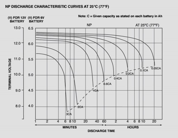
Note that this exemplar battery loaded to 1C
starts 'working' at just over 12 volts. If he
had been fitted with a flight worthy, 17 Ah battery
and could reduce his loads to say 4A (.2C) his
trip home would have been uneventful . . .
I know you shouldn't turn the alternator off when the engine is running however I cycled the Alt Switch to see if i could get it to reset but no change resulted.
There is no rational prohibition for turning the alternator
on/off while the engine is running . . . particularly
if there's a flight worthy battery in service.
At this point I was over water so I requested a direct track to Hobart and landed to check it out (while I still had some volts). By the time I landed I didn't have enough volts to start the engine. I recharged the battery overnight. This morning I started the engine and the Alternator came back on line and operated as normal. After warm ups I obtained a clearance and departed Hobart....3 mins later the Alternator failed again and I returned to Hobart.
What's wrong with this story? After the FIRST failure of
the alternator, the battery was incapable of supporting
sustained flight for more than a few minutes.
Before I shut down I momentarily switched the master switch off and then immediately back on - this recycled the alternator and it was operating normally again. I suspected it may have been an over voltage condition because the EXP2 Buss has over-volt protection which turns off the Alternator and you have to remove battery power to reset it. I did a ground run for approximately 3 minutes at 2200rpm but it continued to operate normally (i thought this might cause it to fail). I shut down and removed the cowls and checked the belt and checked the connectors. Removed and refitted the connector on the back of the Alternator - all seemed fine. Following this I replaced the cowls and then inspected the EXP2 Buss to see if there were any loose connections. All seemed OK. I started the engine again and Alternator was operating normally after run-ups and a higher rpm check. I taxied out to the runway and I watched the indicator panel on departure...shortly after take off (before I had reduced the rpm) the indicator panel showed a high voltage warning which then reverted to a low voltage warning probably due to over volt protection kicking in. I completed the circuit and landed, tied down my RV and came to the conclusion that I wasn't going to fly back over Bass Strait in a hurry so I jumped on a commercial flight home.
The peek-n-poke is a good and necessary part
of the troubleshooting activity. His decision
to use alternate transportation was prudent.
We've discussed system reliability philosophies
here on the list for many years. Crafting design
goals should be followed with design, testing
and maintenance to those goals.
If this gentleman had crafted a plan-b with capable
and confident endurance (can anybody say Z-13/8?)
it's unlikely that this story would have been
written. Yes, things break on airplanes. The real
story here is not the difficulty with his alternator
or it's associated controls. It's about his
ABSOLUTE DEPENDENCE on the alternator for comfortable
transition over deep water.
So now the dilemma - I didn't bring the Alternator home with me so I can't bench test it. My thoughts are to purchase a replacement alternator and take it to Hobart and fit it to see if the problem goes away. If not, then I will have a spare alternator and the problem is more likely to be a fault in the over volt protection on the EXP2 Buss.
Has anyone had a similar experience with the Vans 60amp Alternator and EXP2 Buss combination? If yes - what conclusions did you come to?
I have had a previous Internal Voltage Regulator failure with this same Alternator which was repaired. I believe the previous failure may have been caused by turning on the alternator switch after start up. Ever since that point I have been turning on the Alternator switch prior to start up and turning off after shutdown.
My Engine/Alternator has now done 193 hours.
Any help/thoughts would be appreciated because when I fly back to pick up my RV I want to be confident that I can get it home.
All the rest of this narrative is irrelevant to
the core issues illustrated. This story isn't
about resolving an alternator problem, it's about
lack of SYSTEM reliability.
Bob . . . [quote][b]
| | - The Matronics AeroElectric-List Email Forum - | | | Use the List Feature Navigator to browse the many List utilities available such as the Email Subscriptions page, Archive Search & Download, 7-Day Browse, Chat, FAQ, Photoshare, and much more:
http://www.matronics.com/Navigator?AeroElectric-List |
|
|
|
| Back to top |
|
|
|
|
You cannot post new topics in this forum
You cannot reply to topics in this forum
You cannot edit your posts in this forum
You cannot delete your posts in this forum
You cannot vote in polls in this forum
You cannot attach files in this forum
You can download files in this forum
|
Powered by phpBB © 2001, 2005 phpBB Group
|

