 |
Matronics Email Lists
Web Forum Interface to the Matronics Email Lists
|
| View previous topic :: View next topic |
| Author |
Message |
fidot
Joined: 07 Jul 2019
Posts: 6
|
 Posted: Sun Aug 11, 2019 10:53 pm Post subject: Please critique my Z-11-based electrical design Posted: Sun Aug 11, 2019 10:53 pm Post subject: Please critique my Z-11-based electrical design |
 |
|
Folks,
I am rebuilding an electrical on an experimental 2-hole biplane (a Marquart Charger), and I would like y'all's feedback on my wiring design.
I have attached the full diagram and the load analysis/voltage drop analysis spreadsheet here, and below I have highlighted the main areas of "not sure" or ones where I'd like some feedback, which will be greatly appreciated!
The whole shebang is also posted here: http://79ft.net/entries/2019-08-11-design-v1/ in case you prefer to read it with inline images.
The Design
The design is based on Figure Z-11 from AeroElectric Connection, with the following tweaks:
I'm using the B&C LR3C Voltage Regulator, so it's wiring has been incorporated
I dropped the Endurance and Main Battery busses
I have tweaked the starting switches circuit, main buss feeder, and how ammeter is hooked up - see below for discussion
The diagram is laid out to generally clump the components together as they would be on the airplane. It initially might seem convoluted - but it has a certain flow to it matching the locations of components. Start in bottom right corner for battery/starter/alternator circuitry and go counter clockwise - this will effectively take you "thru the airplane" as the components will be laid out; roughly.
Specific Areas of Attention
Starting / Mags Circuit
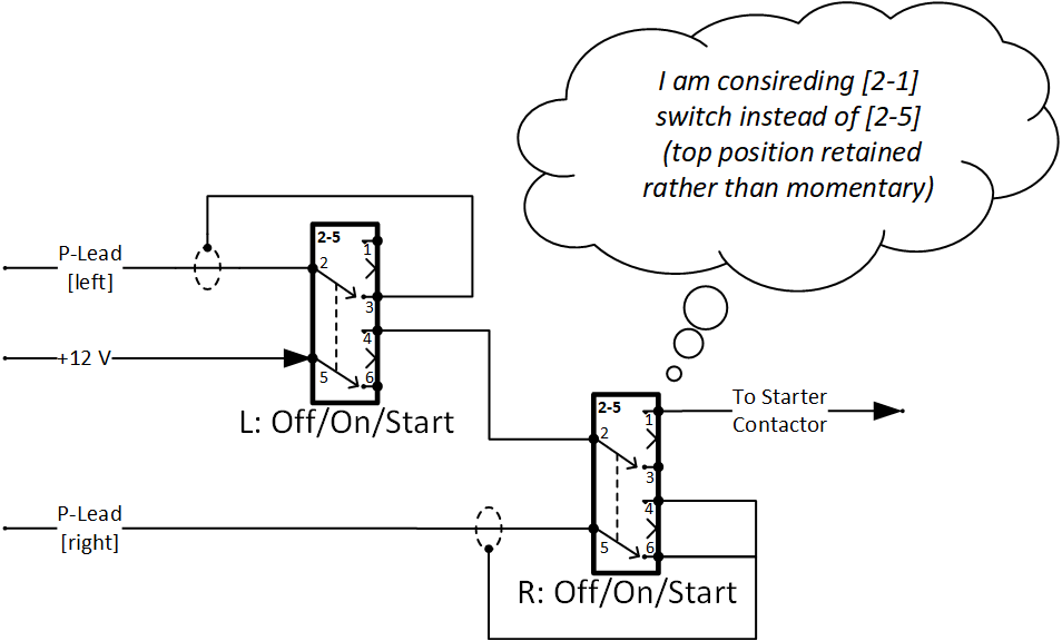
See "Mags / Start Circuit" sub-diagram attached at the end.
This is a deviation from Z-11, with both switches having to be in the momentary up position for starter to engage. I like this better for two reasons:
It makes the act of starting the motor more explicit, and
It returns back to correct "running" position automatically
I need to test the ergonomics of pressing up a couple switches together. If I don't like it, another alternative would be to replace the "Right Mag" switch circuitry from -5 to -1: making the top position on it non-momentary (as noted on the diagram). This will reduce the "user-friendliness" but will still keep the explicitness, especially with my using pull-to-unlock switches from Honeywell.
Main Power Distribution
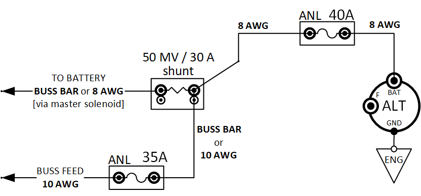
See "Charging and Power Distribution" attachment at the end.
Note that:
Shunt is set up to be in the "battery" lead. I like "battery lead" style ammeters, showing charge current on the 12-o-clock-plus segment, and discharge current on the 12-o-clock-minus segment.
Note that the buss feeder wire is protected by a slow-burn 35A current limiter. In Z-11, that wire is not protected at all. My reasoning for this decision is that this wire is relatively long on my plane (around 4 feet), since fuse block is near the rear cockpit. I wanted to protect it.
One area of concern here is that in the event of alternator short, the Ammeter Shunt will be a part of the alternator circuit that will see a lot of current while the 40A slow burn opens up. My gutfeel says it should be able to handle it, but I am not sure. At any rate, figure Z-11 has the same setup with shunt on the alternator's B-Lead.
Voltage Regulator Sense Wire
LR3C Voltage Regulator needs a separate "voltage sense" wire that one would normally connect to the main buss. Since the regulator in my case is closer to the firewall than to the buss (fuse) block, I am connecting it to the main battery circuitry (jumper wire between Starter and Master contactors). This is somewhat a shorter run and seems that it will be more logical to measure as close to the battery as possible (especially since I'm saving on wire lengths this way). Seems sensible to me.
The sense wire will be 20 AWG, about 3' long, and connected via 24 AWG fuselink
Voltage Regulator Field Supply Circuit
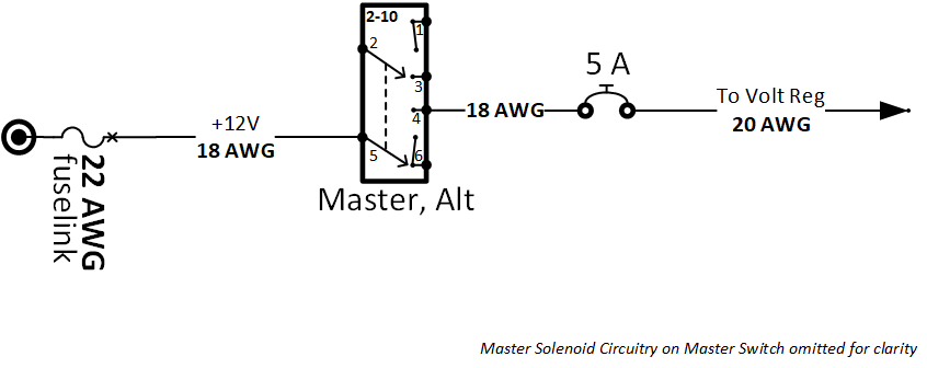
See "Field Supply Circuit" attachment below.
I copied the AeroElectric's figure Z-11 wire gauges here. In Z-11, everything upstream of Breaker is 18 AWG, and everything downstream is 20 AWG, but it's not explained why.
Is this driven by a requirement to ensure that fuselink survives the short in the circuit in case of crowbaring, and the breaker pops first, w/o endangering the fuselink much (18 AWG allows for 22 AWG fuselink instead of 24 AWG)?
Component Locations and Main Connector
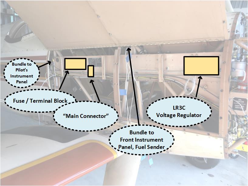
See "Component Locations" diagram in the attachments.
Note that logically, the way one would wire this airplane would be to pre-wire switches and other items that go into the pilot's (back) instrument panel with long pigtails, then install the switches, and tie down wiring behind the panel. Then, the pigtails can be connected to fuse block and loads.
Some of the load wires already exist (lighting for example), and they will have to be spliced to wires coming from switches.
I have decided instead to locate a kind of "Main Connector" right there near the Fuse Block. A wire comes off of the Fuse Block, goes to the switch on the panel, then switched power is returned to the "Main Connector". Load is on the other side of Main Connector. This works for most with a couple exceptions.
This serves a couple purposes:
Create a logical "access point" into the main wire bundle, for reading labels, tracing wires later, and such,
Simplify installation process
Connect to existing load wires that are not being replaced
For now, I am thinking about using Molex 0.093 pins in two housings (I have 13 circuits total to connect via this thing, and want to have room for further expansion). I would love suggestions here. One of the requirements is that it should be easily workable with a multimeter for tracing / testing purposes (I technically could've used D-Sub here , but am not due to this precise reason).
Separate Switch for Turn and Bank
Yes, it's weird to have that. The original electrical had it. I guess, the logic was to be able to shed half an amp of unnecessary load in the event of alternator failure, or it was just done for no good reason.
I'm keeping it  . .
Front Panel Tach
It's a Westach gauge (http://www.westach.com/instructions/Y2AT3-2.jpg) that feeds off of a magneto P-Lead. No separate power going to it.
Westach asks for a 1/4 A inline fuse. But why? Seems unnecessary (we don't need to fuse P-Leads).
Wire going to this tach in my opinion need to be shielded P-Lead wire. Not sure if I'm correct here.
I need to tie into one of the P-Leads. I have three options:
At magneto: I will effectively have two P-Leads coming off of one of them. I have Bendix mags, and connectors on those might make the whole hookup look ugly. Adds extra wire.
At mag switch in the rear panel: just adds extra ~4 feet of wire for no reason.
Y-Split the P-lead as it goes along the fuselage: this seems the most optimal wire-management wise, but I am not sure if splicing into a P-lead is kosher. I don't see any good reasons why that would be bad, but I don't know everything. This will likely be a soldered splice unless I find or someone suggests something better. This is my solution of choice at the moment.
Panel Lighting
I am on the fence on this one. On one hand, I can add a nice LED strip light and dimmer to light the panel up.
On the other hand, this is extra weight, and "this is a biplane! you won't fly it at night!" vs. "well what if you find yourself out late" keeps nagging me. Note: I do not have a landing light (though in a biplane... that's somewhat a non-necessity  ). ).
I am leaning towards doing it, because doing it now will be easy, and I will have the option to see my gauges at night, even if that Dark and Stormy Night will be a result of bad planning rather than an intentional thing.
10 AWG Feeder for Radios
Radio stack was wired via the "Radio Master" switch prior. I was initially going to run separate power feeds to each of the things in the radio stack, but to get to it, I'll need to pull the wings off (yeah...). It's in between pilot's legs attached to the bottom of the cockpit.
So, the feeder is staying. The stack has been wired by previous owner recently, and isn't wired badly - with individual fuses for each radio, and a 10 AWG feeder to it and ground "return" from it.
I'm just putting this "hose" on a 30A fuse, which is more than enough to protect the wire and support all the loads from that stack.
Strobe and Nav on the Same Circuit
I am replacing (TailNav, WingNav) + (old heavy strobe on belly) with SkyBeacon and SkySensor on wingtips and nav/strobe on the tail, but I don't have enough wiring in the fuselage and wings to have a separate circuit for strobes. I do not plan to fly IFR (biplane!) so "strobes in the clouds" is not really an issue. When I will have the rag off the airplane, I will add a separate switching circuit for just the strobes.
--
Well, if you have read it this far, I really appreciate it, and I will really appreciate any comments.
Thanks!
Fedor 'Fidot' Fomichev
Chickenhouse Charger (was 23RG, now 6781G)
| | - The Matronics AeroElectric-List Email Forum - | | | Use the List Feature Navigator to browse the many List utilities available such as the Email Subscriptions page, Archive Search & Download, 7-Day Browse, Chat, FAQ, Photoshare, and much more:
http://www.matronics.com/Navigator?AeroElectric-List |
|
| Description: |
|
| Filesize: |
23.17 KB |
| Viewed: |
3751 Time(s) |

|
| Description: |
| Charging and Power Distribution |
|
| Filesize: |
15.94 KB |
| Viewed: |
3751 Time(s) |

|
| Description: |
|
| Filesize: |
10.62 KB |
| Viewed: |
3751 Time(s) |

|
| Description: |
|
| Filesize: |
62.71 KB |
| Viewed: |
3751 Time(s) |

|
| Description: |
|

Download |
| Filename: |
6781G-wiring-diagram.pdf |
| Filesize: |
271.42 KB |
| Downloaded: |
279 Time(s) |
| Description: |
| Load Schedule, Voltage Drops |
|

Download |
| Filename: |
6781G-wiring_load_schedule.xlsx |
| Filesize: |
23.8 KB |
| Downloaded: |
260 Time(s) |
|
|
| Back to top |
|
 |
user9253
Joined: 28 Mar 2008
Posts: 1927
Location: Riley TWP Michigan
|
 Posted: Mon Aug 12, 2019 4:48 am Post subject: Re: Please critique my Z-11-based electrical design Posted: Mon Aug 12, 2019 4:48 am Post subject: Re: Please critique my Z-11-based electrical design |
 |
|
That main connector is an unnecessary failure point. There are two crimps and the mating pins, a total of 3 failure points for each circuit. And since there are 13 connections, luck in not on your side.  Straight wires with no splices would be much more reliable. How often will it be necessary to unplug that connector? Compare the convenience of unplugging that connector to the inconvenience of troubleshooting and fixing a bad connection. Straight wires with no splices would be much more reliable. How often will it be necessary to unplug that connector? Compare the convenience of unplugging that connector to the inconvenience of troubleshooting and fixing a bad connection.
-
Consider eliminating the 35 amp ANL fuse. There is a reason the main power bus feeder is not fused in Bob's drawings. If it fails, all electrical power is lost. Compare that danger to the chances of the feeder shorting out. If you practice good workmanship, support the feeder well, and double insulate it where it passes through the firewall, then it is not going to short out.
-
The shunt location is a matter of personal preference. I prefer to measure alternator output rather than battery current. Or eliminate the shunt altogether, one less thing to fail. The voltmeter will tell if the alternator is working or not.
Nice schematic. Keep up the good work.
| | - The Matronics AeroElectric-List Email Forum - | | | Use the List Feature Navigator to browse the many List utilities available such as the Email Subscriptions page, Archive Search & Download, 7-Day Browse, Chat, FAQ, Photoshare, and much more:
http://www.matronics.com/Navigator?AeroElectric-List |
|
_________________
Joe Gores |
|
| Back to top |
|
 |
fidot
Joined: 07 Jul 2019
Posts: 6
|
 Posted: Tue Aug 13, 2019 5:43 pm Post subject: Re: Please critique my Z-11-based electrical design Posted: Tue Aug 13, 2019 5:43 pm Post subject: Re: Please critique my Z-11-based electrical design |
 |
|
Joe,
Thanks for commentary! I was not ignoring the thread - just waiting to see if there will be any more comments, to address all of them  . .
--
> main connector as 3 failure points per circuit:
It will probably not gonna get disconnected ever, unless serious repairs are necessary.
This connector is weighed against the fact that absence of it will make troubleshooting extremely aggravating and time consuming, should it ever become necessary; given the physical layout of things and that I am retrofitting here (if I was building the whole new panel, I'd architect it with using sub-panels or similar with easy access). It will also make assembling the system much easier (though I understand this is not a strong argument given that my labor on the plane is $0/hour  ). ).
Suppose I'm using Molex 0.093 crimped pins. I can greatly improve reliability by paying utmost attention to each pin's crimp, or using a touch of solder if I doubt them (or, just using solder to ensure the connection is electrically sound). I do have a good crimper, having tested a few crappy ones  . .
Just to give you an example: let's say, my Master Switch circuit isn't doing the right thing. If I have the Main Connector, I effectively have access to the "switch" side of things, as well as the "load" side of things to trace and measure. If I don't have it, I only effectively have access on the load side; and accessing the switch side requires a lot of contortions.
Side note: when tracing old wiring (which lead to this project), I did have access to things on a similarly set up "terminal block" - and I still, climbing the XXXth time around the flying wires, managed to twist out my knee such that I was immobile for a couple days
What would be great is if someone could suggest the connector type to use here.....
- Milspec terminal block: too bulky
- "Transformer"-style terminal block with #6 screws - possible, though security of those screws needs to be considered; and it's heavier (relatively)
- Molex - I was looking at 0.093 series and the MLX series. I want "backside access" for multimeter probes...
---
> consider eliminating the 35 amp ANL fuse.
Possible fire hazard vs slightly higher probability of total electrical failure is basically the tradeoff here. I erred on the size of virtually eliminating former at the expense of small increase of probability of the latter (someone accidentally dinging that wire without noticing is also in realm of possibilities, however remote).
I do have somewhat an elevated fear of letting the magic smoke out in this ship because of it being a tube and rag, with gas tank between the passenger's legs kind of ship...
On the other hand, my reasoning was that I actually am completely non-dependent on electrical system on this plane - while annoying, even at night, it is not required for the safe completion of the flight. Yes, I will lose my tach, engine 3-in-1, radios, and lights - but that's a minor affair in a $100 burger airplane IMHO.
Now, an interesting question is what are the chances of the buss feeder ANL opening without a good reason? If they're known to do that, then this might be a consideration...
Note that I'm sizing a 35AMP ANL for a setup where all downstream fuses are 5A or less except for one other, buss -> radio stack, feeder wire (which I will try to make as small as I can). My understanding of ANLs is that they will be able to withstand shorted circuits blowing small fuses downstream...
| | - The Matronics AeroElectric-List Email Forum - | | | Use the List Feature Navigator to browse the many List utilities available such as the Email Subscriptions page, Archive Search & Download, 7-Day Browse, Chat, FAQ, Photoshare, and much more:
http://www.matronics.com/Navigator?AeroElectric-List |
|
|
|
| Back to top |
|
 |
user9253
Joined: 28 Mar 2008
Posts: 1927
Location: Riley TWP Michigan
|
 Posted: Tue Aug 13, 2019 6:29 pm Post subject: Re: Please critique my Z-11-based electrical design Posted: Tue Aug 13, 2019 6:29 pm Post subject: Re: Please critique my Z-11-based electrical design |
 |
|
A trick that I have used for troubleshooting and testing a wire, when there is no test point, is to poke through the wire insulation with a needle or Exacto knife.  Probe that sharp object with the voltmeter.  The small hole in the insulation requires little, if any, repairing.

Having a connector will make troubleshooting easier.  On the other hand, if that connector wasn't there, then there wouldn't be any trouble to troubleshoot.

-

An ANL fuse is unlikely to blow.  However, the crimped terminals and fasteners are unnecessary failure points.  And bare terminals present a short circuit hazard.  So the fuse is creating a hazard that it is intended to protect against.

-

The nice thing about building your own airplane is that you get to add lots of little features that are important to you.  So go ahead and wire it the way that you want to.  I see no major design flaws.
| | - The Matronics AeroElectric-List Email Forum - | | | Use the List Feature Navigator to browse the many List utilities available such as the Email Subscriptions page, Archive Search & Download, 7-Day Browse, Chat, FAQ, Photoshare, and much more:
http://www.matronics.com/Navigator?AeroElectric-List |
|
_________________
Joe Gores |
|
| Back to top |
|
 |
|
|
You cannot post new topics in this forum
You cannot reply to topics in this forum
You cannot edit your posts in this forum
You cannot delete your posts in this forum
You cannot vote in polls in this forum
You cannot attach files in this forum
You can download files in this forum
|
Powered by phpBB © 2001, 2005 phpBB Group
|


