rbs80
Joined: 30 Nov 2020
Posts: 10
Location: Virginia
|
 Posted: Fri Jan 08, 2021 2:53 pm Post subject: RV10 Electrical System Safety Posted: Fri Jan 08, 2021 2:53 pm Post subject: RV10 Electrical System Safety |
 |
|
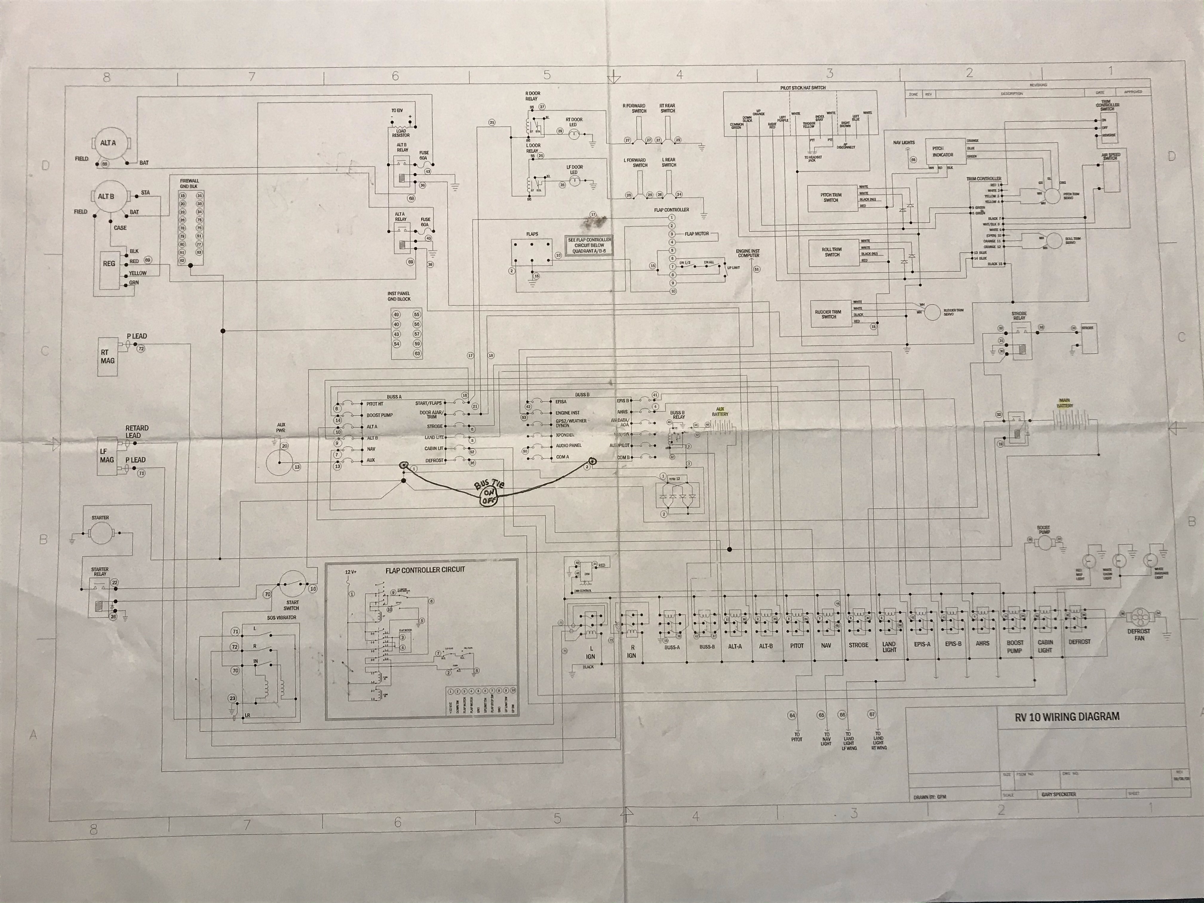
Hey guys I am way in over my head on this forum but a nice man from BandC suggested I try.  Attached is the electrical diagram of my recently purchased RV10. It was completed in 2009 and the avionics was switched to a Garmin 900x a year later.  My issue is it safe and operationally sound. It is an “###”X” design; if that is familiar.


Apparently the builder added a “bus tie” in order to bypass a diode (bridge rectifier type) because the draw to recharge the “Aux Battery” (2 wheel chair batteries 7Ah 12v wired in series) reduced the essential bus voltage to 12.6v. This “bus tie” when on boosts both busses back to 13.6v. Is this how it was meant to be run?


Additionally with both alternators on, the displayed “alternator amperage” seems to be all over the scale; sometimes 45-50 amps when the airplane has most accessories off. Feeding both alternators into a single “bus bar” seems to cause issues and is that safe?


Therefore it’s been recommended that I swap out the Stby Alt for a 60A PP alternator and just use it as the primary power source.  My preference would be going to a “xxxZ” plan where each alternator powers its own bus but I’ve been advised against that. (The good news is my A&P figured out the shunt had not been changed per Garmin install instructional, a 100A 50 milivolts currently on order.)


Sorry for the length of this. William Booth
| | - The Matronics AeroElectric-List Email Forum - | | | Use the List Feature Navigator to browse the many List utilities available such as the Email Subscriptions page, Archive Search & Download, 7-Day Browse, Chat, FAQ, Photoshare, and much more:
http://www.matronics.com/Navigator?AeroElectric-List |
|
| Description: |
|
| Filesize: |
1.96 MB |
| Viewed: |
1262 Time(s) |

|
|
|


