 |
Matronics Email Lists
Web Forum Interface to the Matronics Email Lists
|
| View previous topic :: View next topic |
| Author |
Message |
cluros(at)gmail.com
Guest
|
 Posted: Thu Dec 23, 2021 9:18 am Post subject: ULPower Alternator/Regulator Posted: Thu Dec 23, 2021 9:18 am Post subject: ULPower Alternator/Regulator |
 |
|
Does anyone have experience with this system? My friend is installing a UL350 Engine and their wiring diagram and instructions specify no protective devices between the alternator and the battery.


Does anyone know if this alternator/regulator combination can suffer from an overvoltage event? Or is the regulator fault tolerant?

Regards,

Sebastien
| | - The Matronics AeroElectric-List Email Forum - | | | Use the List Feature Navigator to browse the many List utilities available such as the Email Subscriptions page, Archive Search & Download, 7-Day Browse, Chat, FAQ, Photoshare, and much more:
http://www.matronics.com/Navigator?AeroElectric-List |
|
|
|
| Back to top |
|
 |
user9253
Joined: 28 Mar 2008
Posts: 1927
Location: Riley TWP Michigan
|
| Posted: Thu Dec 23, 2021 11:34 am Post subject: Re: ULPower Alternator/Regulator |
|
|
When the alternator "B" lead shorts to ground, the pilot will be lucky if there is no

fire when the "B" lead turns white hot and melts from high battery current.

Now that the alternator is no longer connected, the electrical

system relies on the battery.  But half of the battery energy has already been

depleted melting the "B" lead.  Either a large fuse or fusible link should

protect the "B" lead from excessive battery current, regardless of what UL Power says.
| | - The Matronics AeroElectric-List Email Forum - | | | Use the List Feature Navigator to browse the many List utilities available such as the Email Subscriptions page, Archive Search & Download, 7-Day Browse, Chat, FAQ, Photoshare, and much more:
http://www.matronics.com/Navigator?AeroElectric-List |
|
_________________
Joe Gores |
|
| Back to top |
|
|
nuckolls.bob(at)aeroelect
Guest
|
| Posted: Thu Dec 23, 2021 2:01 pm Post subject: ULPower Alternator/Regulator |
|
|
At 11:16 AM 12/23/2021, you wrote:
| Quote: | Does anyone have experience with this system? My friend is installing a
UL350 Engine and their wiring diagram and instructions specify no protective
devices between the alternator and the battery. |
Protecting b-lead wiring from hard faults within
the alternator itself is a legacy protocol in
T/C aircraft since the first Ford alternator was
bolted to a Cessna (approx 1964).
However, LOTS of automotive applications tie
the alternator b-lead right to battery (+)
(like my '87 GMC) with some later models
adding a fusible link at the battery end
(like the 97 Chevy I worked on last week).
What kind of alternator is on the UL350, wound
field or permanent magnet?
| Quote: | Does anyone know if this alternator/regulator combination
can suffer from an overvoltage event? Or is the regulator
fault tolerant? |
There is NO alternator system immune to OV events.
Probability, severity and risk run the gamut from
a little puff of smoke to a major incendiary event.
That needs to be sorted out in a failure mode
effects analysis with appropriate prophylactics
incorporated.
As supplier of the system, the engine manufacturer
SHOULD have conducted those studies and published
well considered protocols in their manual . . .
unfortunately, few engine suppliers have any notion
of what that process entails.
The usual answer to a query on the matter is: "we've
got xxxx of these flying with no reported events of
noteworthy magnitude."
For this List to offer any more considered advice,
much more data are needed as to system characteristics.
The SAFE thing is to incorporate b-lead and ov protection
as a matter of policy . . . it's light, cheap and better
to have it and not need it as opposed to needing and
not having.
Bob . . .
Un impeachable logic: George Carlin asked, "If black boxes
survive crashes, why don't they make the whole airplane
out of that stuff?"
| | - The Matronics AeroElectric-List Email Forum - | | | Use the List Feature Navigator to browse the many List utilities available such as the Email Subscriptions page, Archive Search & Download, 7-Day Browse, Chat, FAQ, Photoshare, and much more:
http://www.matronics.com/Navigator?AeroElectric-List |
|
|
|
| Back to top |
|
|
dj_theis
Joined: 28 Aug 2017
Posts: 56
Location: Minnesota
|
| Posted: Fri Dec 24, 2021 6:29 am Post subject: Re: ULPower Alternator/Regulator |
|
|
| Quote: | What kind of alternator is on the UL350, wound
field or permanent magnet? |
From their website, all the UL 350 engines are listed as having integrated PMA charging systems with external R/R. All listed at 30 amp total and requiring 15 amps for the engine ignition and fuel pumps, leaving15 amps for Avionics.
https://ulpower.com/en/engines/ul350/ul350is
| | - The Matronics AeroElectric-List Email Forum - | | | Use the List Feature Navigator to browse the many List utilities available such as the Email Subscriptions page, Archive Search & Download, 7-Day Browse, Chat, FAQ, Photoshare, and much more:
http://www.matronics.com/Navigator?AeroElectric-List |
|
_________________
Dan Theis
Scratch building Sonex #1362
Still working on the Revmaster Alternator improvement |
|
| Back to top |
|
|
dj_theis
Joined: 28 Aug 2017
Posts: 56
Location: Minnesota
|
| Posted: Fri Dec 24, 2021 6:30 am Post subject: Re: ULPower Alternator/Regulator |
|
|
| Quote: | What kind of alternator is on the UL350, wound
field or permanent magnet? |
From their website, all the UL 350 engines are listed as having integrated PMA charging systems with external R/R. All listed at 30 amp total and requiring 15 amps for the engine ignition and fuel pumps, leaving15 amps for Avionics.
https://ulpower.com/en/engines/ul350/ul350is
| | - The Matronics AeroElectric-List Email Forum - | | | Use the List Feature Navigator to browse the many List utilities available such as the Email Subscriptions page, Archive Search & Download, 7-Day Browse, Chat, FAQ, Photoshare, and much more:
http://www.matronics.com/Navigator?AeroElectric-List |
|
_________________
Dan Theis
Scratch building Sonex #1362
Still working on the Revmaster Alternator improvement |
|
| Back to top |
|
|
cluros(at)gmail.com
Guest
|
| Posted: Fri Dec 24, 2021 8:24 pm Post subject: ULPower Alternator/Regulator |
|
|
As Dan already posted, the alternator is permanent magnet.
I was wondering more if anyone knows if the voltage regulator has any over-voltage protection included. ULPower are apparently very good about responding to inquiries so I will send them an email and post the reply to this list.
In any case, the electrical system on the aircraft in question has already been installed but was designed by a highly qualified and experienced electrical & robotics engineer with no GA aircraft knowledge. The aircraft owner sent me the diagram so that I could admire it but a quick and dirty FMEA showed some problems. A review of the manufacturer's instructions lead me to suggest that they rewire it to conform with those instructions but since the alternator wiring already includes a current limiter and a solenoid I thought it would be appropriate to leave those in rather than create the problem Joe pointed out vis a vis shorted b lead.1 If I can get permission I will post the schematic to the list; notwithstanding its problematic features it's quite a work of art.
Regards,
Sebastien
On Thu, Dec 23, 2021 at 2:11 PM Robert L. Nuckolls, III <nuckolls.bob(at)aeroelectric.com (nuckolls.bob(at)aeroelectric.com)> wrote:
| Quote: | At 11:16 AM 12/23/2021, you wrote:
| Quote: | Does anyone have experience with this system? My friend is installing a
UL350 Engine and their wiring diagram and instructions specify no protective
devices between the alternator and the battery. |
Protecting b-lead wiring from hard faults within
the alternator itself is a legacy protocol in
T/C aircraft since the first Ford alternator was
bolted to a Cessna (approx 1964).
However, LOTS of automotive applications tie
the alternator b-lead right to battery (+)
(like my '87 GMC) with some later models
adding a fusible link at the battery end
(like the 97 Chevy I worked on last week).
What kind of alternator is on the UL350, wound
field or permanent magnet?
| Quote: | Does anyone know if this alternator/regulator combination
can suffer from an overvoltage event? Or is the regulator
fault tolerant? |
There is NO alternator system immune to OV events.
Probability, severity and risk run the gamut from
a little puff of smoke to a major incendiary event.
That needs to be sorted out in a failure mode
effects analysis with appropriate prophylactics
incorporated.
As supplier of the system, the engine manufacturer
SHOULD have conducted those studies and published
well considered protocols in their manual . . .
unfortunately, few engine suppliers have any notion
of what that process entails.
The usual answer to a query on the matter is: "we've
got xxxx of these flying with no reported events of
noteworthy magnitude."
For this List to offer any more considered advice,
much more data are needed as to system characteristics.
The SAFE thing is to incorporate b-lead and ov protection
as a matter of policy . . . it's light, cheap and better
to have it and not need it as opposed to needing and
not having.
Bob . . .
Un impeachable logic: George Carlin asked, "If black boxes
survive crashes, why don't they make the whole airplane
out of that stuff?"
|
| | - The Matronics AeroElectric-List Email Forum - | | | Use the List Feature Navigator to browse the many List utilities available such as the Email Subscriptions page, Archive Search & Download, 7-Day Browse, Chat, FAQ, Photoshare, and much more:
http://www.matronics.com/Navigator?AeroElectric-List |
|
|
|
| Back to top |
|
|
nuckolls.bob(at)aeroelect
Guest
|
| Posted: Sun Dec 26, 2021 1:33 pm Post subject: ULPower Alternator/Regulator |
|
|
| Quote: | | >From their website, all the UL 350 engines are listed as having integrated PMA charging systems with external R/R. All listed at 30 amp total and requiring 15 amps for the engine ignition and fuel pumps, leaving15 amps for Avionics. |
Okay, thanks . . . is there a recommended system
wiring diagram I can access?
Bob . . .
Un impeachable logic: George Carlin asked, "If black boxes
survive crashes, why don't they make the whole airplane
out of that stuff?"
| | - The Matronics AeroElectric-List Email Forum - | | | Use the List Feature Navigator to browse the many List utilities available such as the Email Subscriptions page, Archive Search & Download, 7-Day Browse, Chat, FAQ, Photoshare, and much more:
http://www.matronics.com/Navigator?AeroElectric-List |
|
|
|
| Back to top |
|
|
cluros(at)gmail.com
Guest
|
| Posted: Sun Dec 26, 2021 1:55 pm Post subject: ULPower Alternator/Regulator |
|
|
On Sun, Dec 26, 2021 at 1:37 PM Robert L. Nuckolls, III <nuckolls.bob(at)aeroelectric.com (nuckolls.bob(at)aeroelectric.com)> wrote:
| Quote: | | Quote: | | >From their website, all the UL 350 engines are listed as having integrated PMA charging systems with external R/R. All listed at 30 amp total and requiring 15 amps for the engine ignition and fuel pumps, leaving15 amps for Avionics. |
Okay, thanks . . . is there a recommended system
wiring diagram I can access?
Bob . . .
Un impeachable logic: George Carlin asked, "If black boxes
survive crashes, why don't they make the whole airplane
out of that stuff?"
|
| | - The Matronics AeroElectric-List Email Forum - | | | Use the List Feature Navigator to browse the many List utilities available such as the Email Subscriptions page, Archive Search & Download, 7-Day Browse, Chat, FAQ, Photoshare, and much more:
http://www.matronics.com/Navigator?AeroElectric-List |
|
| Description: |
|

Download |
| Filename: |
UL350_Electrical_System.pdf |
| Filesize: |
385.81 KB |
| Downloaded: |
247 Time(s) |
|
|
| Back to top |
|
|
user9253
Joined: 28 Mar 2008
Posts: 1927
Location: Riley TWP Michigan
|
| Posted: Sun Dec 26, 2021 5:28 pm Post subject: Re: ULPower Alternator/Regulator |
|
|
If that 40 amp fuse blows, the engine quits.  Remove it.

Repurpose that 40 amp fuse to protect the electrical system from a shorted

alternator or its "B" lead.  Or use a fuselink.

Good workmanship will prevent the engine busbar from shorting out.

Relocate the engine Fuses.  They should be between the busbar and the switches.

The 60 amp fuse is not needed.  Eliminate it.

I suggest that you use battery contactor in series with the aircraft main power bus

(not to be confused with the engine bus).

There should be a fuse between the engine busbar and the start push button.
| | - The Matronics AeroElectric-List Email Forum - | | | Use the List Feature Navigator to browse the many List utilities available such as the Email Subscriptions page, Archive Search & Download, 7-Day Browse, Chat, FAQ, Photoshare, and much more:
http://www.matronics.com/Navigator?AeroElectric-List |
|
_________________
Joe Gores |
|
| Back to top |
|
|
nuckolls.bob(at)aeroelect
Guest
|
| Posted: Mon Dec 27, 2021 4:16 pm Post subject: ULPower Alternator/Regulator |
|
|
At 10:23 PM 12/24/2021, you wrote:
| Quote: | If I can get permission I will post the schematic to the list; notwithstanding its problematic features it's quite a work of art.
Regards,
Sebastien
|
Is this document published on the 'net? If so, permission to republish
should not be an issue as long as original source is not obscured.
If you know of a link, you can share that and let people download
themselves.
Bob . . .
Un impeachable logic: George Carlin asked, "If black boxes
survive crashes, why don't they make the whole airplane
out of that stuff?"
| | - The Matronics AeroElectric-List Email Forum - | | | Use the List Feature Navigator to browse the many List utilities available such as the Email Subscriptions page, Archive Search & Download, 7-Day Browse, Chat, FAQ, Photoshare, and much more:
http://www.matronics.com/Navigator?AeroElectric-List |
|
|
|
| Back to top |
|
|
cluros(at)gmail.com
Guest
|
| Posted: Mon Dec 27, 2021 4:23 pm Post subject: ULPower Alternator/Regulator |
|
|
No, it was sent to me by a member of our local Recreational Aircraft Association and was created by a friend of his for his Zenith 750.
On Mon, Dec 27, 2021, 19:19 Robert L. Nuckolls, III <nuckolls.bob(at)aeroelectric.com (nuckolls.bob(at)aeroelectric.com)> wrote:
| Quote: | At 10:23 PM 12/24/2021, you wrote:
| Quote: | If I can get permission I will post the schematic to the list; notwithstanding its problematic features it's quite a work of art.
Regards,
Sebastien
|
Is this document published on the 'net? If so, permission to republish
should not be an issue as long as original source is not obscured.
If you know of a link, you can share that and let people download
themselves.
Bob . . .
Un impeachable logic: George Carlin asked, "If black boxes
survive crashes, why don't they make the whole airplane
out of that stuff?"
|
| | - The Matronics AeroElectric-List Email Forum - | | | Use the List Feature Navigator to browse the many List utilities available such as the Email Subscriptions page, Archive Search & Download, 7-Day Browse, Chat, FAQ, Photoshare, and much more:
http://www.matronics.com/Navigator?AeroElectric-List |
|
|
|
| Back to top |
|
|
Ceengland
Joined: 11 Oct 2020
Posts: 391
Location: MS
|
| Posted: Mon Dec 27, 2021 4:30 pm Post subject: ULPower Alternator/Regulator |
|
|
On 12/27/2021 6:15 PM, Robert L. Nuckolls, III wrote:
| Quote: | At 10:23 PM 12/24/2021, you wrote:
| Quote: | If I can get permission I will post the schematic to the list; notwithstanding its problematic features it's quite a work of art.
Regards,
Sebastien
|
Is this document published on the 'net? If so, permission to republish
should not be an issue as long as original source is not obscured.
If you know of a link, you can share that and let people download
themselves.
Bob . . .
|
A little google-foo yields:
https://ulpower.com/en/engines/manuals
The website itself doesn't seem to have a public-facing link to the page, but there it is.
Charlie
 Virus-free. www.avast.com [url=#DAB4FAD8-2DD7-40BB-A1B8-4E2AA1F9FDF2] [/url] Virus-free. www.avast.com [url=#DAB4FAD8-2DD7-40BB-A1B8-4E2AA1F9FDF2] [/url]
| | - The Matronics AeroElectric-List Email Forum - | | | Use the List Feature Navigator to browse the many List utilities available such as the Email Subscriptions page, Archive Search & Download, 7-Day Browse, Chat, FAQ, Photoshare, and much more:
http://www.matronics.com/Navigator?AeroElectric-List |
|
_________________
Charlie |
|
| Back to top |
|
|
Ceengland
Joined: 11 Oct 2020
Posts: 391
Location: MS
|
| Posted: Mon Dec 27, 2021 4:32 pm Post subject: ULPower Alternator/Regulator |
|
|
On 12/27/2021 6:22 PM, Sebastien wrote:
| Quote: | No, it was sent to me by a member of our local Recreational
Aircraft Association and was created by a friend of his for his Zenith
750.
I thought we were talking about ULPower's diagram in their installation
|
manual. Are we talking about some individual's self-created diagram?
--
This email has been checked for viruses by Avast antivirus software.
https://www.avast.com/antivirus
| | - The Matronics AeroElectric-List Email Forum - | | | Use the List Feature Navigator to browse the many List utilities available such as the Email Subscriptions page, Archive Search & Download, 7-Day Browse, Chat, FAQ, Photoshare, and much more:
http://www.matronics.com/Navigator?AeroElectric-List |
|
_________________
Charlie |
|
| Back to top |
|
|
cluros(at)gmail.com
Guest
|
| Posted: Mon Dec 27, 2021 4:54 pm Post subject: ULPower Alternator/Regulator |
|
|
There are two documents mentioned in this discussion Charlie. One is the ULPower diagram I attached to the thread, the other is a document that I cannot share at this time. I was reviewing this document and found several problems with it and was trying to help them correct these problems by pointing them to the installation instructions from ULPower. Unfortunately while these instructions are much better than their current architecture, I'm still finding them problematic for their own reasons as Joe and Bob have pointed out. I have also pointed them to the AEC and Z101b.
They seem receptive to suggestions but the aircraft is already built. I'm not sure how far they are willing to redo the electrical system. As it stands there are 3 circuit protective devices, one solenoid, and one switch between the battery and the EDC. The alternator power goes through 2 extra protective devices and an additional solenoid before getting to the EDC for a whopping total of 8 points of failure in series between alternator and engine but only 5 from the battery.
On Mon, Dec 27, 2021 at 4:35 PM Charlie England <ceengland7(at)gmail.com (ceengland7(at)gmail.com)> wrote:
| Quote: | --> AeroElectric-List message posted by: Charlie England <ceengland7(at)gmail.com (ceengland7(at)gmail.com)>
On 12/27/2021 6:22 PM, Sebastien wrote:
> No, it was sent to me by a member of our local Recreational
> Aircraft Association and was created by a friend of his for his Zenith
> 750.
I thought we were talking about ULPower's diagram in their installation
manual. Are we talking about some individual's self-created diagram?
--
This email has been checked for viruses by Avast antivirus software.
https://www.avast.com/antivirus
===========
-
Electric-List" rel="noreferrer" target="_blank">http://www.matronics.com/Navigator?AeroElectric-List
===========
FORUMS -
eferrer" target="_blank">http://forums.matronics.com
===========
WIKI -
errer" target="_blank">http://wiki.matronics.com
===========
b Site -
-Matt Dralle, List Admin.
="noreferrer" target="_blank">https://matronics.com/contribution
===========
|
| | - The Matronics AeroElectric-List Email Forum - | | | Use the List Feature Navigator to browse the many List utilities available such as the Email Subscriptions page, Archive Search & Download, 7-Day Browse, Chat, FAQ, Photoshare, and much more:
http://www.matronics.com/Navigator?AeroElectric-List |
|
|
|
| Back to top |
|
|
Ceengland
Joined: 11 Oct 2020
Posts: 391
Location: MS
|
| Posted: Mon Dec 27, 2021 5:21 pm Post subject: ULPower Alternator/Regulator |
|
|
On 12/27/2021 6:53 PM, Sebastien wrote:
| Quote: | There are two documents mentioned in this discussion Charlie. One is the ULPower diagram I attached to the thread, the other is a document that I cannot share at this time. I was reviewing this document and found several problems with it and was trying to help them correct these problems by pointing them to the installation instructions from ULPower. Unfortunately while these instructions are much better than their current architecture, I'm still finding them problematic for their own reasons as Joe and Bob have pointed out. I have also pointed them to the AEC and Z101b.
They seem receptive to suggestions but the aircraft is already built. I'm not sure how far they are willing to redo the electrical system. As it stands there are 3 circuit protective devices, one solenoid, and one switch between the battery and the EDC. The alternator power goes through 2 extra protective devices and an additional solenoid before getting to the EDC for a whopping total of 8 points of failure in series between alternator and engine but only 5 from the battery.
On Mon, Dec 27, 2021 at 4:35 PM Charlie England <ceengland7(at)gmail.com (ceengland7(at)gmail.com)> wrote:
| Quote: | --> AeroElectric-List message posted by: Charlie England <ceengland7(at)gmail.com (ceengland7(at)gmail.com)>
On 12/27/2021 6:22 PM, Sebastien wrote:
> No, it was sent to me by a member of our local Recreational
> Aircraft Association and was created by a friend of his for his Zenith
> 750.
I thought we were talking about ULPower's diagram in their installation
manual. Are we talking about some individual's self-created diagram?
|
|
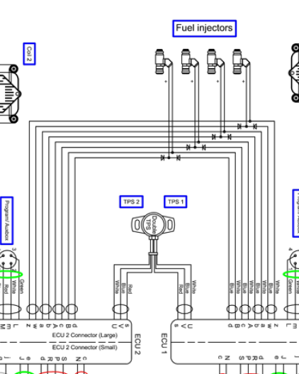
Ah; got it now. If it's a dual ECU, the factory diagram has its own issues, that while they may not be single points of outright failure, they could cause serious issues with engine operation. For instance, it looks like a failed injector current sink (switches, labeled A, B, a, & z) in either ECU could cause the injector to stay open.
[img]cid:part1.nZY0Ilt8.ek2QY5wG(at)gmail.com[/img] Virus-free. www.avast.com [url=#DAB4FAD8-2DD7-40BB-A1B8-4E2AA1F9FDF2] [/url]
| | - The Matronics AeroElectric-List Email Forum - | | | Use the List Feature Navigator to browse the many List utilities available such as the Email Subscriptions page, Archive Search & Download, 7-Day Browse, Chat, FAQ, Photoshare, and much more:
http://www.matronics.com/Navigator?AeroElectric-List |
|
| Description: |
|
| Filesize: |
80.27 KB |
| Viewed: |
6225 Time(s) |
|
_________________
Charlie |
|
| Back to top |
|
|
cluros(at)gmail.com
Guest
|
| Posted: Mon Dec 27, 2021 5:32 pm Post subject: ULPower Alternator/Regulator |
|
|
In this particular case it's a single ECU installation. Single battery and alernator as well.
On Mon, Dec 27, 2021, 20:25 Charlie England <ceengland7(at)gmail.com (ceengland7(at)gmail.com)> wrote:
| Quote: | On 12/27/2021 6:53 PM, Sebastien wrote:
| Quote: | There are two documents mentioned in this discussion Charlie. One is the ULPower diagram I attached to the thread, the other is a document that I cannot share at this time. I was reviewing this document and found several problems with it and was trying to help them correct these problems by pointing them to the installation instructions from ULPower. Unfortunately while these instructions are much better than their current architecture, I'm still finding them problematic for their own reasons as Joe and Bob have pointed out. I have also pointed them to the AEC and Z101b.
They seem receptive to suggestions but the aircraft is already built. I'm not sure how far they are willing to redo the electrical system. As it stands there are 3 circuit protective devices, one solenoid, and one switch between the battery and the EDC. The alternator power goes through 2 extra protective devices and an additional solenoid before getting to the EDC for a whopping total of 8 points of failure in series between alternator and engine but only 5 from the battery.
On Mon, Dec 27, 2021 at 4:35 PM Charlie England <ceengland7(at)gmail.com (ceengland7(at)gmail.com)> wrote:
| Quote: | --> AeroElectric-List message posted by: Charlie England <ceengland7(at)gmail.com (ceengland7(at)gmail.com)>
On 12/27/2021 6:22 PM, Sebastien wrote:
> No, it was sent to me by a member of our local Recreational
> Aircraft Association and was created by a friend of his for his Zenith
> 750.
I thought we were talking about ULPower's diagram in their installation
manual. Are we talking about some individual's self-created diagram?
|
|
Ah; got it now. If it's a dual ECU, the factory diagram has its own issues, that while they may not be single points of outright failure, they could cause serious issues with engine operation. For instance, it looks like a failed injector current sink (switches, labeled A, B, a, & z) in either ECU could cause the injector to stay open.
[img]cid:part1.nZY0Ilt8.ek2QY5wG(at)gmail.com[/img]
Virus-free. www.avast.com [url=#m_-8456691566823616747_DAB4FAD8-2DD7-40BB-A1B8-4E2AA1F9FDF2] [/url]
|
| | - The Matronics AeroElectric-List Email Forum - | | | Use the List Feature Navigator to browse the many List utilities available such as the Email Subscriptions page, Archive Search & Download, 7-Day Browse, Chat, FAQ, Photoshare, and much more:
http://www.matronics.com/Navigator?AeroElectric-List |
|
| Description: |
|
| Filesize: |
80.27 KB |
| Viewed: |
6225 Time(s) |

|
| Description: |
|
| Filesize: |
80.27 KB |
| Viewed: |
6225 Time(s) |

|
|
|
| Back to top |
|
|
yellowduckduo(at)gmail.co
Guest
|
| Posted: Mon Dec 27, 2021 5:48 pm Post subject: ULPower Alternator/Regulator |
|
|
I've found that a failed open injector in flight is of little concern.
At high power settings it may not even be noticed. At mid power levels
it might run a little rough. Close the throttle too far and it merely
encourages you to not reduce power too much until you have to. Most
injectors are sized to run fairly high duty cycles at full power.
Ken
On 27/12/2021 8:26 PM, Charlie England wrote:
| Quote: | On 12/27/2021 6:53 PM, Sebastien wrote:
> There are two documents mentioned in this discussion Charlie. One is
> the ULPower diagram I attached to the thread, the other is a document
> that I cannot share at this time. I was reviewing this document and
> found several problems with it and was trying to help them correct
> these problems by pointing them to the installation instructions from
> ULPower. Unfortunately while these instructions are much better than
> their current architecture, I'm still finding them problematic for
> their own reasons as Joe and Bob have pointed out. I have also
> pointed them to the AEC and Z101b.
>
> They seem receptive to suggestions but the aircraft is already built.
> I'm not sure how far they are willing to redo the electrical system.
> As it stands there are 3 circuit protective devices, one solenoid,
> and one switch between the battery and the EDC. The alternator power
> goes through 2 extra protective devices and an additional solenoid
> before getting to the EDC for a whopping total of 8 points of failure
> in series between alternator and engine but only 5 from the battery.
>
> On Mon, Dec 27, 2021 at 4:35 PM Charlie England
> <ceengland7(at)gmail.com> wrote:
>
>
> <ceengland7(at)gmail.com>
>
> On 12/27/2021 6:22 PM, Sebastien wrote:
> > No, it was sent to me by a member of our local Recreational
> > Aircraft Association and was created by a friend of his for his
> Zenith
> > 750.
> I thought we were talking about ULPower's diagram in their
> installation
> manual. Are we talking about some individual's self-created diagram?
>
Ah; got it now. If it's a dual ECU, the factory diagram has its own
issues, that while they may not be single points of outright failure,
they could cause serious issues with engine operation. For instance,
it looks like a failed injector current sink (switches, labeled A, B,
a, & z) in either ECU could cause the injector to stay open.
<https://www.avast.com/sig-email?utm_medium=email&utm_source=link&utm_campaign=sig-email&utm_content=emailclient&utm_term=icon>
Virus-free. www.avast.com
<https://www.avast.com/sig-email?utm_medium=email&utm_source=link&utm_campaign=sig-email&utm_content=emailclient&utm_term=link>
<#DAB4FAD8-2DD7-40BB-A1B8-4E2AA1F9FDF2>
|
| | - The Matronics AeroElectric-List Email Forum - | | | Use the List Feature Navigator to browse the many List utilities available such as the Email Subscriptions page, Archive Search & Download, 7-Day Browse, Chat, FAQ, Photoshare, and much more:
http://www.matronics.com/Navigator?AeroElectric-List |
|
|
|
| Back to top |
|
|
|
|
You cannot post new topics in this forum
You cannot reply to topics in this forum
You cannot edit your posts in this forum
You cannot delete your posts in this forum
You cannot vote in polls in this forum
You cannot attach files in this forum
You can download files in this forum
|
Powered by phpBB © 2001, 2005 phpBB Group
|

